2003 JEEP GRAND CHEROKEE stall
[x] Cancel search: stallPage 1277 of 2199
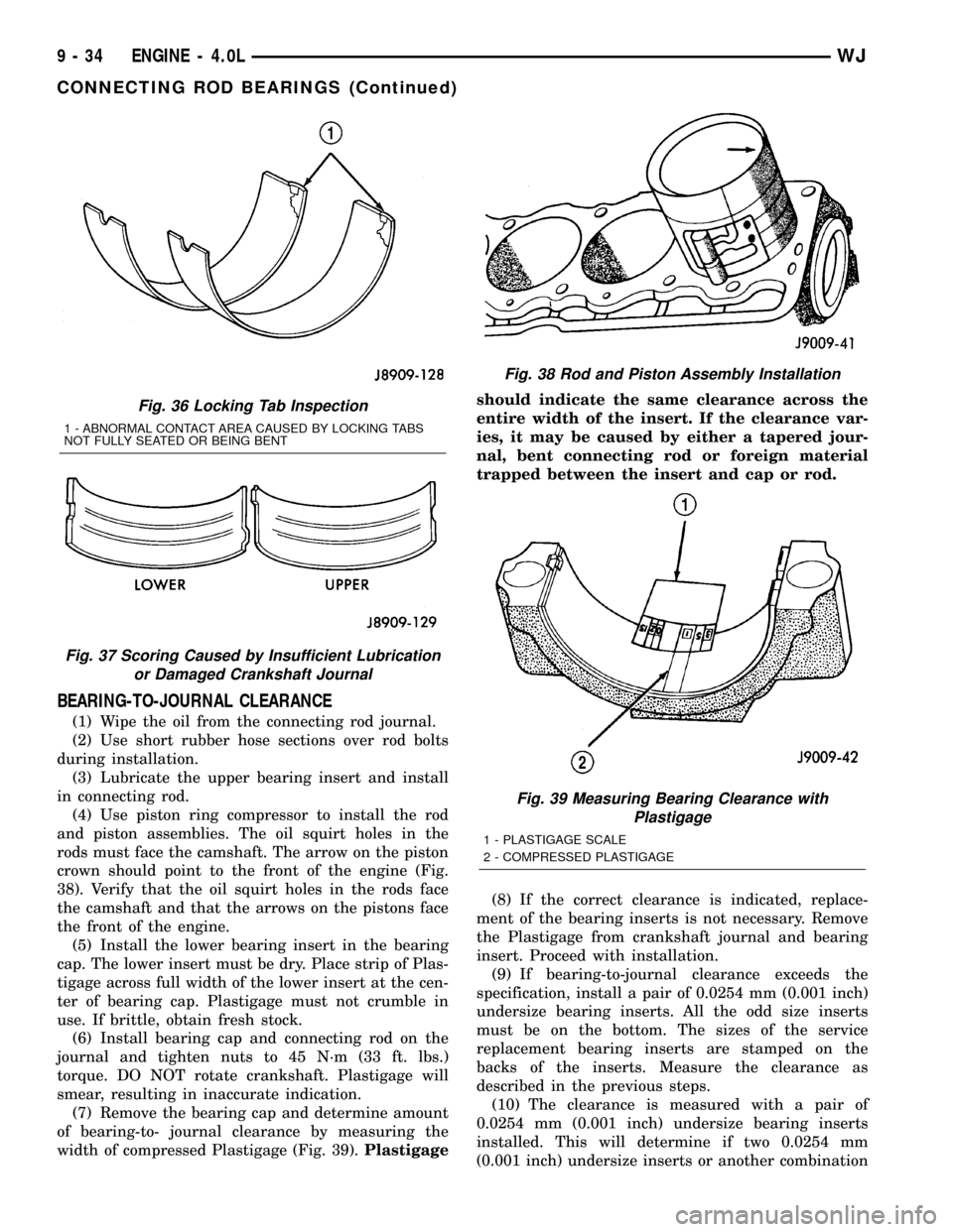
BEARING-TO-JOURNAL CLEARANCE
(1) Wipe the oil from the connecting rod journal.
(2) Use short rubber hose sections over rod bolts
during installation.
(3) Lubricate the upper bearing insert and install
in connecting rod.
(4) Use piston ring compressor to install the rod
and piston assemblies. The oil squirt holes in the
rods must face the camshaft. The arrow on the piston
crown should point to the front of the engine (Fig.
38). Verify that the oil squirt holes in the rods face
the camshaft and that the arrows on the pistons face
the front of the engine.
(5) Install the lower bearing insert in the bearing
cap. The lower insert must be dry. Place strip of Plas-
tigage across full width of the lower insert at the cen-
ter of bearing cap. Plastigage must not crumble in
use. If brittle, obtain fresh stock.
(6) Install bearing cap and connecting rod on the
journal and tighten nuts to 45 N´m (33 ft. lbs.)
torque. DO NOT rotate crankshaft. Plastigage will
smear, resulting in inaccurate indication.
(7) Remove the bearing cap and determine amount
of bearing-to- journal clearance by measuring the
width of compressed Plastigage (Fig. 39).Plastigageshould indicate the same clearance across the
entire width of the insert. If the clearance var-
ies, it may be caused by either a tapered jour-
nal, bent connecting rod or foreign material
trapped between the insert and cap or rod.
(8) If the correct clearance is indicated, replace-
ment of the bearing inserts is not necessary. Remove
the Plastigage from crankshaft journal and bearing
insert. Proceed with installation.
(9) If bearing-to-journal clearance exceeds the
specification, install a pair of 0.0254 mm (0.001 inch)
undersize bearing inserts. All the odd size inserts
must be on the bottom. The sizes of the service
replacement bearing inserts are stamped on the
backs of the inserts. Measure the clearance as
described in the previous steps.
(10) The clearance is measured with a pair of
0.0254 mm (0.001 inch) undersize bearing inserts
installed. This will determine if two 0.0254 mm
(0.001 inch) undersize inserts or another combination
Fig. 36 Locking Tab Inspection
1 - ABNORMAL CONTACT AREA CAUSED BY LOCKING TABS
NOT FULLY SEATED OR BEING BENT
Fig. 37 Scoring Caused by Insufficient Lubrication
or Damaged Crankshaft Journal
Fig. 38 Rod and Piston Assembly Installation
Fig. 39 Measuring Bearing Clearance with
Plastigage
1 - PLASTIGAGE SCALE
2 - COMPRESSED PLASTIGAGE
9 - 34 ENGINE - 4.0LWJ
CONNECTING ROD BEARINGS (Continued)
Page 1278 of 2199
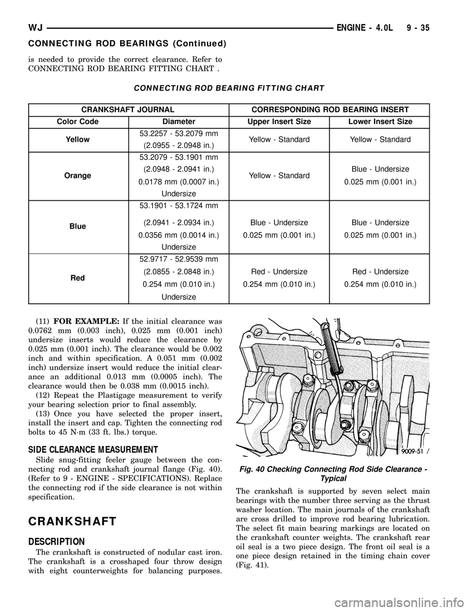
is needed to provide the correct clearance. Refer to
CONNECTING ROD BEARING FITTING CHART .
CONNECTING ROD BEARING FITTING CHART
CRANKSHAFT JOURNAL CORRESPONDING ROD BEARING INSERT
Color Code Diameter Upper Insert Size Lower Insert Size
Yellow53.2257 - 53.2079 mm
Yellow - Standard Yellow - Standard
(2.0955 - 2.0948 in.)
Orange53.2079 - 53.1901 mm
Yellow - StandardBlue - Undersize (2.0948 - 2.0941 in.)
0.0178 mm (0.0007 in.) 0.025 mm (0.001 in.)
Undersize
Blue53.1901 - 53.1724 mm
Blue - Undersize Blue - Undersize (2.0941 - 2.0934 in.)
0.0356 mm (0.0014 in.) 0.025 mm (0.001 in.) 0.025 mm (0.001 in.)
Undersize
Red52.9717 - 52.9539 mm
Red - Undersize Red - Undersize (2.0855 - 2.0848 in.)
0.254 mm (0.010 in.) 0.254 mm (0.010 in.) 0.254 mm (0.010 in.)
Undersize
(11)FOR EXAMPLE:If the initial clearance was
0.0762 mm (0.003 inch), 0.025 mm (0.001 inch)
undersize inserts would reduce the clearance by
0.025 mm (0.001 inch). The clearance would be 0.002
inch and within specification. A 0.051 mm (0.002
inch) undersize insert would reduce the initial clear-
ance an additional 0.013 mm (0.0005 inch). The
clearance would then be 0.038 mm (0.0015 inch).
(12) Repeat the Plastigage measurement to verify
your bearing selection prior to final assembly.
(13) Once you have selected the proper insert,
install the insert and cap. Tighten the connecting rod
bolts to 45 N´m (33 ft. lbs.) torque.
SIDE CLEARANCE MEASUREMENT
Slide snug-fitting feeler gauge between the con-
necting rod and crankshaft journal flange (Fig. 40).
(Refer to 9 - ENGINE - SPECIFICATIONS). Replace
the connecting rod if the side clearance is not within
specification.
CRANKSHAFT
DESCRIPTION
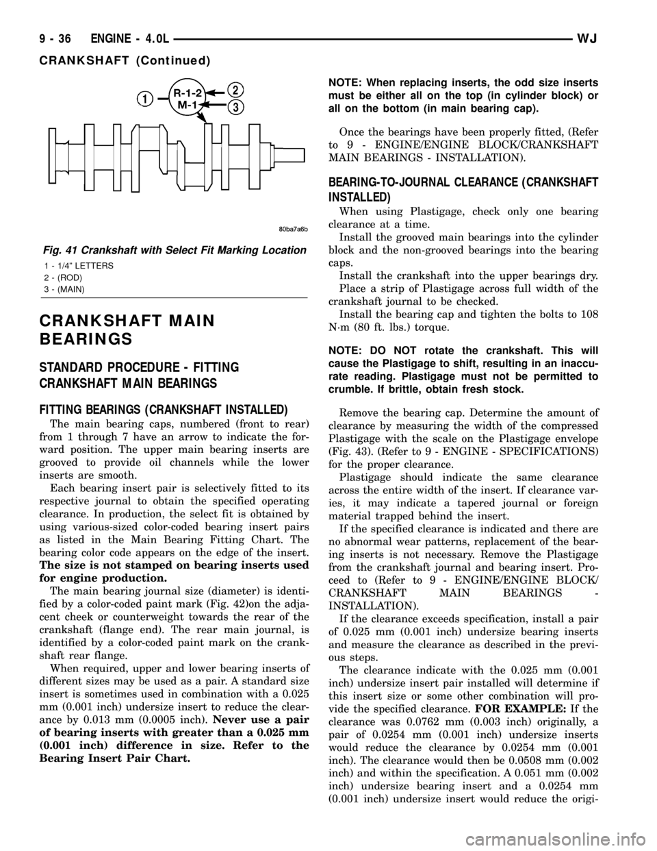
The crankshaft is constructed of nodular cast iron.
The crankshaft is a crosshaped four throw design
with eight counterweights for balancing purposes.The crankshaft is supported by seven select main
bearings with the number three serving as the thrust
washer location. The main journals of the crankshaft
are cross drilled to improve rod bearing lubrication.
The select fit main bearing markings are located on
the crankshaft counter weights. The crankshaft rear
oil seal is a two piece design. The front oil seal is a
one piece design retained in the timing chain cover
(Fig. 41).
Fig. 40 Checking Connecting Rod Side Clearance -
Typical
WJENGINE - 4.0L 9 - 35
CONNECTING ROD BEARINGS (Continued)
Page 1279 of 2199
CRANKSHAFT MAIN
BEARINGS
STANDARD PROCEDURE - FITTING
CRANKSHAFT MAIN BEARINGS
FITTING BEARINGS (CRANKSHAFT INSTALLED)
The main bearing caps, numbered (front to rear)
from 1 through 7 have an arrow to indicate the for-
ward position. The upper main bearing inserts are
grooved to provide oil channels while the lower
inserts are smooth.
Each bearing insert pair is selectively fitted to its
respective journal to obtain the specified operating
clearance. In production, the select fit is obtained by
using various-sized color-coded bearing insert pairs
as listed in the Main Bearing Fitting Chart. The
bearing color code appears on the edge of the insert.
The size is not stamped on bearing inserts used
for engine production.
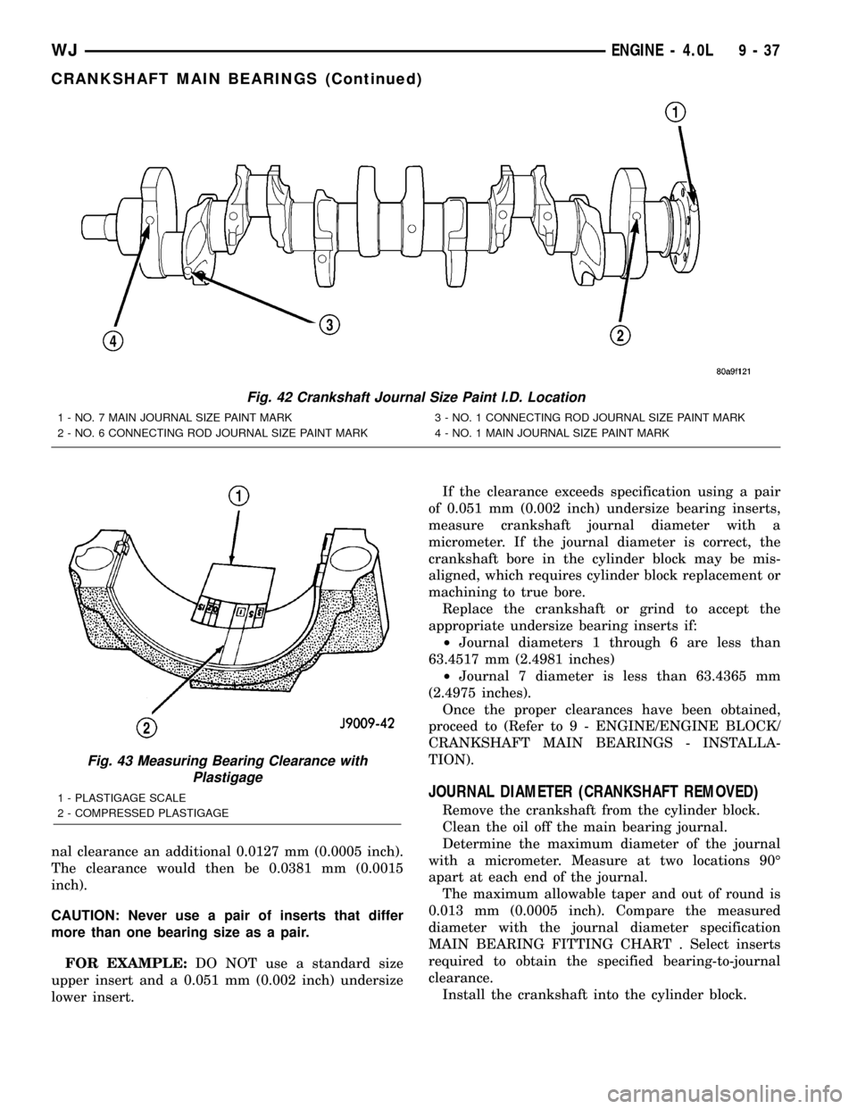
The main bearing journal size (diameter) is identi-
fied by a color-coded paint mark (Fig. 42)on the adja-
cent cheek or counterweight towards the rear of the
crankshaft (flange end). The rear main journal, is
identified by a color-coded paint mark on the crank-
shaft rear flange.
When required, upper and lower bearing inserts of
different sizes may be used as a pair. A standard size
insert is sometimes used in combination with a 0.025
mm (0.001 inch) undersize insert to reduce the clear-
ance by 0.013 mm (0.0005 inch).Never use a pair
of bearing inserts with greater than a 0.025 mm
(0.001 inch) difference in size. Refer to the
Bearing Insert Pair Chart.NOTE: When replacing inserts, the odd size inserts
must be either all on the top (in cylinder block) or
all on the bottom (in main bearing cap).
Once the bearings have been properly fitted, (Refer
to 9 - ENGINE/ENGINE BLOCK/CRANKSHAFT
MAIN BEARINGS - INSTALLATION).
BEARING-TO-JOURNAL CLEARANCE (CRANKSHAFT
INSTALLED)
When using Plastigage, check only one bearing
clearance at a time.
Install the grooved main bearings into the cylinder
block and the non-grooved bearings into the bearing
caps.
Install the crankshaft into the upper bearings dry.
Place a strip of Plastigage across full width of the
crankshaft journal to be checked.
Install the bearing cap and tighten the bolts to 108
N´m (80 ft. lbs.) torque.
NOTE: DO NOT rotate the crankshaft. This will
cause the Plastigage to shift, resulting in an inaccu-
rate reading. Plastigage must not be permitted to
crumble. If brittle, obtain fresh stock.
Remove the bearing cap. Determine the amount of
clearance by measuring the width of the compressed
Plastigage with the scale on the Plastigage envelope
(Fig. 43). (Refer to 9 - ENGINE - SPECIFICATIONS)
for the proper clearance.
Plastigage should indicate the same clearance
across the entire width of the insert. If clearance var-
ies, it may indicate a tapered journal or foreign
material trapped behind the insert.
If the specified clearance is indicated and there are
no abnormal wear patterns, replacement of the bear-
ing inserts is not necessary. Remove the Plastigage
from the crankshaft journal and bearing insert. Pro-
ceed to (Refer to 9 - ENGINE/ENGINE BLOCK/
CRANKSHAFT MAIN BEARINGS -
INSTALLATION).
If the clearance exceeds specification, install a pair
of 0.025 mm (0.001 inch) undersize bearing inserts
and measure the clearance as described in the previ-
ous steps.
The clearance indicate with the 0.025 mm (0.001
inch) undersize insert pair installed will determine if
this insert size or some other combination will pro-
vide the specified clearance.FOR EXAMPLE:If the
clearance was 0.0762 mm (0.003 inch) originally, a
pair of 0.0254 mm (0.001 inch) undersize inserts
would reduce the clearance by 0.0254 mm (0.001
inch). The clearance would then be 0.0508 mm (0.002
inch) and within the specification. A 0.051 mm (0.002
inch) undersize bearing insert and a 0.0254 mm
(0.001 inch) undersize insert would reduce the origi-
Fig. 41 Crankshaft with Select Fit Marking Location
1 - 1/4º LETTERS
2 - (ROD)
3 - (MAIN)
9 - 36 ENGINE - 4.0LWJ
CRANKSHAFT (Continued)
Page 1280 of 2199
nal clearance an additional 0.0127 mm (0.0005 inch).
The clearance would then be 0.0381 mm (0.0015
inch).
CAUTION: Never use a pair of inserts that differ
more than one bearing size as a pair.
FOR EXAMPLE:DO NOT use a standard size
upper insert and a 0.051 mm (0.002 inch) undersize
lower insert.If the clearance exceeds specification using a pair
of 0.051 mm (0.002 inch) undersize bearing inserts,
measure crankshaft journal diameter with a
micrometer. If the journal diameter is correct, the
crankshaft bore in the cylinder block may be mis-
aligned, which requires cylinder block replacement or
machining to true bore.
Replace the crankshaft or grind to accept the
appropriate undersize bearing inserts if:
²Journal diameters 1 through 6 are less than
63.4517 mm (2.4981 inches)
²Journal 7 diameter is less than 63.4365 mm
(2.4975 inches).
Once the proper clearances have been obtained,
proceed to (Refer to 9 - ENGINE/ENGINE BLOCK/
CRANKSHAFT MAIN BEARINGS - INSTALLA-
TION).
JOURNAL DIAMETER (CRANKSHAFT REMOVED)
Remove the crankshaft from the cylinder block.
Clean the oil off the main bearing journal.
Determine the maximum diameter of the journal
with a micrometer. Measure at two locations 90É
apart at each end of the journal.
The maximum allowable taper and out of round is
0.013 mm (0.0005 inch). Compare the measured
diameter with the journal diameter specification
MAIN BEARING FITTING CHART . Select inserts
required to obtain the specified bearing-to-journal
clearance.
Install the crankshaft into the cylinder block.
Fig. 42 Crankshaft Journal Size Paint I.D. Location
1 - NO. 7 MAIN JOURNAL SIZE PAINT MARK
2 - NO. 6 CONNECTING ROD JOURNAL SIZE PAINT MARK3 - NO. 1 CONNECTING ROD JOURNAL SIZE PAINT MARK
4 - NO. 1 MAIN JOURNAL SIZE PAINT MARK
Fig. 43 Measuring Bearing Clearance with
Plastigage
1 - PLASTIGAGE SCALE
2 - COMPRESSED PLASTIGAGE
WJENGINE - 4.0L 9 - 37
CRANKSHAFT MAIN BEARINGS (Continued)
Page 1283 of 2199
INSPECTION
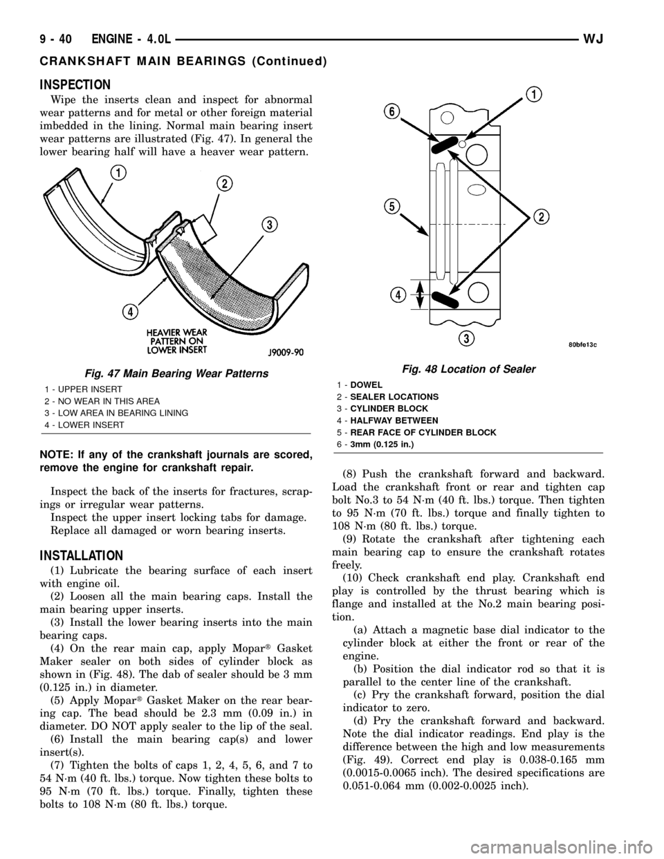
Wipe the inserts clean and inspect for abnormal
wear patterns and for metal or other foreign material
imbedded in the lining. Normal main bearing insert
wear patterns are illustrated (Fig. 47). In general the
lower bearing half will have a heaver wear pattern.
NOTE: If any of the crankshaft journals are scored,
remove the engine for crankshaft repair.
Inspect the back of the inserts for fractures, scrap-
ings or irregular wear patterns.
Inspect the upper insert locking tabs for damage.
Replace all damaged or worn bearing inserts.
INSTALLATION
(1) Lubricate the bearing surface of each insert
with engine oil.
(2) Loosen all the main bearing caps. Install the
main bearing upper inserts.
(3) Install the lower bearing inserts into the main
bearing caps.
(4) On the rear main cap, apply MopartGasket
Maker sealer on both sides of cylinder block as
shown in (Fig. 48). The dab of sealer should be 3 mm
(0.125 in.) in diameter.
(5) Apply MopartGasket Maker on the rear bear-
ing cap. The bead should be 2.3 mm (0.09 in.) in
diameter. DO NOT apply sealer to the lip of the seal.
(6) Install the main bearing cap(s) and lower
insert(s).
(7) Tighten the bolts of caps 1, 2, 4, 5, 6, and 7 to
54 N´m (40 ft. lbs.) torque. Now tighten these bolts to
95 N´m (70 ft. lbs.) torque. Finally, tighten these
bolts to 108 N´m (80 ft. lbs.) torque.(8) Push the crankshaft forward and backward.
Load the crankshaft front or rear and tighten cap
bolt No.3 to 54 N´m (40 ft. lbs.) torque. Then tighten
to 95 N´m (70 ft. lbs.) torque and finally tighten to
108 N´m (80 ft. lbs.) torque.
(9) Rotate the crankshaft after tightening each
main bearing cap to ensure the crankshaft rotates
freely.
(10) Check crankshaft end play. Crankshaft end
play is controlled by the thrust bearing which is
flange and installed at the No.2 main bearing posi-
tion.
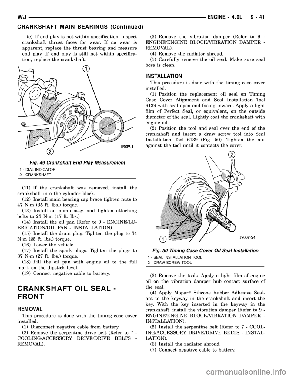
(a) Attach a magnetic base dial indicator to the
cylinder block at either the front or rear of the
engine.
(b) Position the dial indicator rod so that it is
parallel to the center line of the crankshaft.
(c) Pry the crankshaft forward, position the dial
indicator to zero.
(d) Pry the crankshaft forward and backward.
Note the dial indicator readings. End play is the
difference between the high and low measurements
(Fig. 49). Correct end play is 0.038-0.165 mm
(0.0015-0.0065 inch). The desired specifications are
0.051-0.064 mm (0.002-0.0025 inch).
Fig. 47 Main Bearing Wear Patterns
1 - UPPER INSERT
2 - NO WEAR IN THIS AREA
3 - LOW AREA IN BEARING LINING
4 - LOWER INSERT
Fig. 48 Location of Sealer
1-DOWEL
2-SEALER LOCATIONS
3-CYLINDER BLOCK
4-HALFWAY BETWEEN
5-REAR FACE OF CYLINDER BLOCK
6-3mm (0.125 in.)
9 - 40 ENGINE - 4.0LWJ
CRANKSHAFT MAIN BEARINGS (Continued)
Page 1284 of 2199
(e) If end play is not within specification, inspect
crankshaft thrust faces for wear. If no wear is
apparent, replace the thrust bearing and measure
end play. If end play is still not within specifica-
tion, replace the crankshaft.
(11) If the crankshaft was removed, install the
crankshaft into the cylinder block.
(12) Install main bearing cap brace tighten nuts to
47 N´m (35 ft. lbs.) torque.
(13) Install oil pump assy. and tighten attaching
bolts to 23 N´m (17 ft. lbs.)
(14) Install the oil pan (Refer to 9 - ENGINE/LU-
BRICATION/OIL PAN - INSTALLATION).
(15) Install the drain plug. Tighten the plug to 34
N´m (25 ft. lbs.) torque.
(16) Lower the vehicle.
(17) Install the spark plugs. Tighten the plugs to
37 N´m (27 ft. lbs.) torque.
(18) Fill the oil pan with engine oil to the full
mark on the dipstick level.
(19) Connect negative cable to battery.
CRANKSHAFT OIL SEAL -
FRONT
REMOVAL
This procedure is done with the timing case cover
installed.
(1) Disconnect negative cable from battery.
(2) Remove the serpentine drive belt (Refer to 7 -
COOLING/ACCESSORY DRIVE/DRIVE BELTS -
REMOVAL).(3) Remove the vibration damper (Refer to 9 -
ENGINE/ENGINE BLOCK/VIBRATION DAMPER -
REMOVAL).
(4) Remove the radiator shroud.
(5) Carefully remove the oil seal. Make sure seal
bore is clean.
INSTALLATION
This procedure is done with the timing case cover
installed.
(1) Position the replacement oil seal on Timing
Case Cover Alignment and Seal Installation Tool
6139 with seal open end facing inward. Apply a light
film of Perfect Seal, or equivalent, on the outside
diameter of the seal. Lightly coat the crankshaft with
engine oil.
(2) Position the tool and seal over the end of the
crankshaft and insert a draw screw tool into Seal
Installation Tool 6139 (Fig. 50). Tighten the nut
against the tool until it contacts the cover.
(3) Remove the tools. Apply a light film of engine
oil on the vibration damper hub contact surface of
the seal.
(4) Apply MopartSilicone Rubber Adhesive Seal-
ant to the keyway in the crankshaft and insert the
key. With the key inserted in the keyway in the
crankshaft, install the vibration damper (Refer to 9 -
ENGINE/ENGINE BLOCK/VIBRATION DAMPER -
INSTALLATION).
(5) Install the serpentine belt (Refer to 7 - COOL-
ING/ACCESSORY DRIVE/DRIVE BELTS - INSTAL-
LATION).
(6) Install the radiator shroud.
(7) Connect negative cable to battery.
Fig. 49 Crankshaft End Play Measurement
1 - DIAL INDICATOR
2 - CRANKSHAFT
Fig. 50 Timing Case Cover Oil Seal Installation
1 - SEAL INSTALLATION TOOL
2 - DRAW SCREW TOOL
WJENGINE - 4.0L 9 - 41
CRANKSHAFT MAIN BEARINGS (Continued)
Page 1285 of 2199
CRANKSHAFT OIL SEAL -
REAR
REMOVAL
The crankshaft rear main bearing oil seal consists
of two half pieces of viton with a single lip that effec-
tively seals the rear of the crankshaft. Replace the
upper and lower seal halves as a unit to ensure leak-
free operation.
(1) Remove transmission inspection cover.
(2) Remove oil pan. (Refer to 9 - ENGINE/LUBRI-
CATION/OIL PAN - REMOVAL)
(3) Remove main bearing cap brace.
(4) Remove rear main bearing cap (No.7).
(5) Push upper seal out of the groove. Ensure that
the crankshaft and seal groove are not damaged.
(6) Remove lower half of the seal from the bearing
cap.
INSTALLATION
The crankshaft rear main bearing oil seal consists
of two half pieces of viton with a single lip that effec-
tively seals the rear of the crankshaft. Replace the
upper and lower seal halves as a unit to ensure leak-
free operation.
(1) Wipe the seal surface area of the crankshaft
until it is clean.
(2) Apply a thin coat of engine oil.
(3) Coat lip of the seal with engine oil.
(4) Carefully position the upper seal into the
groove in the cylinder block. The lip of the seal faces
toward the front of the engine.
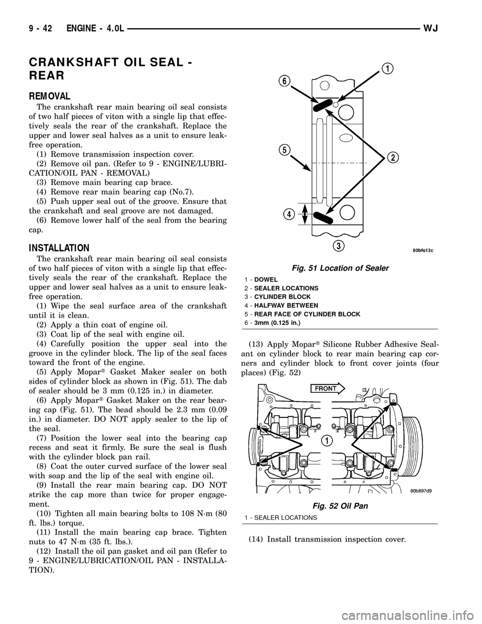
(5) Apply MopartGasket Maker sealer on both
sides of cylinder block as shown in (Fig. 51). The dab
of sealer should be 3 mm (0.125 in.) in diameter.
(6) Apply MopartGasket Maker on the rear bear-
ing cap (Fig. 51). The bead should be 2.3 mm (0.09
in.) in diameter. DO NOT apply sealer to the lip of
the seal.
(7) Position the lower seal into the bearing cap
recess and seat it firmly. Be sure the seal is flush
with the cylinder block pan rail.
(8) Coat the outer curved surface of the lower seal
with soap and the lip of the seal with engine oil.
(9) Install the rear main bearing cap. DO NOT
strike the cap more than twice for proper engage-
ment.
(10) Tighten all main bearing bolts to 108 N´m (80
ft. lbs.) torque.
(11) Install the main bearing cap brace. Tighten
nuts to 47 N´m (35 ft. lbs.).
(12) Install the oil pan gasket and oil pan (Refer to
9 - ENGINE/LUBRICATION/OIL PAN - INSTALLA-
TION).(13) Apply MopartSilicone Rubber Adhesive Seal-
ant on cylinder block to rear main bearing cap cor-
ners and cylinder block to front cover joints (four
places) (Fig. 52)
(14) Install transmission inspection cover.
Fig. 51 Location of Sealer
1-DOWEL
2-SEALER LOCATIONS
3-CYLINDER BLOCK
4-HALFWAY BETWEEN
5-REAR FACE OF CYLINDER BLOCK
6-3mm (0.125 in.)
Fig. 52 Oil Pan
1 - SEALER LOCATIONS
9 - 42 ENGINE - 4.0LWJ
Page 1286 of 2199
HYDRAULIC LIFTERS
DESCRIPTION
Valve lash is controlled by hydraulic tappets
located inside the cylinder block, in tappet bores
above the camshaft.
REMOVAL
NOTE: Retain all the components in the same order
as removed.
(1) Remove the engine cylinder head(Refer to 9 -
ENGINE/CYLINDER HEAD - REMOVAL).
(2) Remove the push rods.
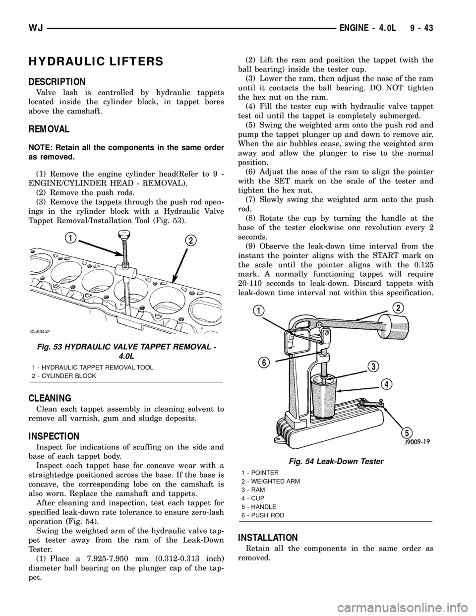
(3) Remove the tappets through the push rod open-
ings in the cylinder block with a Hydraulic Valve
Tappet Removal/Installation Tool (Fig. 53).
CLEANING
Clean each tappet assembly in cleaning solvent to
remove all varnish, gum and sludge deposits.
INSPECTION
Inspect for indications of scuffing on the side and
base of each tappet body.
Inspect each tappet base for concave wear with a
straightedge positioned across the base. If the base is
concave, the corresponding lobe on the camshaft is
also worn. Replace the camshaft and tappets.
After cleaning and inspection, test each tappet for
specified leak-down rate tolerance to ensure zero-lash
operation (Fig. 54).
Swing the weighted arm of the hydraulic valve tap-
pet tester away from the ram of the Leak-Down
Tester.
(1) Place a 7.925-7.950 mm (0.312-0.313 inch)
diameter ball bearing on the plunger cap of the tap-
pet.(2) Lift the ram and position the tappet (with the
ball bearing) inside the tester cup.
(3) Lower the ram, then adjust the nose of the ram
until it contacts the ball bearing. DO NOT tighten
the hex nut on the ram.
(4) Fill the tester cup with hydraulic valve tappet
test oil until the tappet is completely submerged.
(5) Swing the weighted arm onto the push rod and
pump the tappet plunger up and down to remove air.
When the air bubbles cease, swing the weighted arm
away and allow the plunger to rise to the normal
position.
(6) Adjust the nose of the ram to align the pointer
with the SET mark on the scale of the tester and
tighten the hex nut.
(7) Slowly swing the weighted arm onto the push
rod.
(8) Rotate the cup by turning the handle at the
base of the tester clockwise one revolution every 2
seconds.
(9) Observe the leak-down time interval from the
instant the pointer aligns with the START mark on
the scale until the pointer aligns with the 0.125
mark. A normally functioning tappet will require
20-110 seconds to leak-down. Discard tappets with
leak-down time interval not within this specification.
INSTALLATION
Retain all the components in the same order as
removed.
Fig. 53 HYDRAULIC VALVE TAPPET REMOVAL -
4.0L
1 - HYDRAULIC TAPPET REMOVAL TOOL
2 - CYLINDER BLOCK
Fig. 54 Leak-Down Tester
1 - POINTER
2 - WEIGHTED ARM
3 - RAM
4 - CUP
5 - HANDLE
6 - PUSH ROD
WJENGINE - 4.0L 9 - 43