Page 1950 of 2199

HEADLINER
REMOVAL
CAUTION: The headliner is a one-piece, molded
component. It has limited flexibility and must not be
bent. Damage may possibly result.
(1) Record radio presets and disconnect negative
battery cable.
(2) Remove A pillar trim moldings (Refer to 23 -
BODY/INTERIOR/A-PILLAR TRIM - REMOVAL).
(3) Remove B pillar upper trim moldings (Refer to
23 - BODY/INTERIOR/B-PILLAR UPPER TRIM -
REMOVAL).
(4) Remove C pillar trim moldings (Refer to 23 -
BODY/INTERIOR/C-PILLAR TRIM - REMOVAL).
(5) Remove D pillar trim molding (Refer to 23 -
BODY/INTERIOR/D-PILLAR TRIM - REMOVAL).
(6) Remove the sun visors (Refer to 23 - BODY/IN-
TERIOR/SUN VISOR - REMOVAL).
(7) Disconnect the vanity lamp electrical connector.
(8) Remove assist handles from roof rails (Refer to
23 - BODY/INTERIOR/ASSIST HANDLE - REMOV-
AL).
(9) Remove dome lamp and overhead console, if
equipped.
(10) Remove rear cargo/dome lamp.
(11) Remove sun roof pinch welt, if equipped.
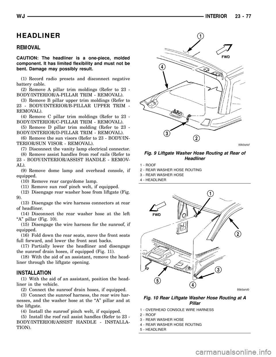
(12) Disengage rear washer hose from liftgate (Fig.
9).
(13) Disengage the wire harness connectors at rear
of headliner.
(14) Disconnect the rear washer hose at the left
ªAº pillar (Fig. 10).
(15) Disengage the wire harness for the sunroof, if
equipped.
(16) Fold down the rear seats, move the front seats
full forward, and lower the front seat backs.
(17) Partially lower the headliner and disengage
the sunroof drain hoses, if equipped (Fig. 11).
(18) With the aid of an assistant, remove the head-
liner through the liftgate opening.
INSTALLATION
(1) With the aid of an assistant, position the head-
liner in the vehicle.
(2) Connect the sunroof drain hoses, if equipped.
(3) Connect the sunroof harness, the rear wire har-
nesses, and the washer hose at the ªAº pillar and at
the liftgate.
(4) Install the sunroof pinch welt, if equipped.
(5) Install the roof rail assist handles (Refer to 23 -
BODY/INTERIOR/ASSIST HANDLE - INSTALLA-
TION).
Fig. 9 Liftgate Washer Hose Routing at Rear of
Headliner
1 - ROOF
2 - REAR WASHER HOSE ROUTING
3 - REAR WASHER HOSE
4 - HEADLINER
Fig. 10 Rear Liftgate Washer Hose Routing at A
Pillar
1 - OVERHEAD CONSOLE WIRE HARNESS
2 - ROOF
3 - REAR WASHER HOSE
4 - REAR WASHER HOSE ROUTING
5 - HEADLINER
WJINTERIOR 23 - 77
Page 1951 of 2199
(6) Install the sun visors (Refer to 23 - BODY/IN-
TERIOR/SUN VISOR - INSTALLATION).
(7) Install the overhead console, if equipped.
(8) Install the rear cargo/dome lamp.
(9) Install the D pillar trim (Refer to 23 - BODY/
INTERIOR/D-PILLAR TRIM - INSTALLATION).(10) Install the C pillar trim (Refer to 23 - BODY/
INTERIOR/C-PILLAR TRIM - INSTALLATION).
(11) Install the upper B pillar trim (Refer to 23 -
BODY/INTERIOR/B-PILLAR UPPER TRIM -
INSTALLATION).
(12) Install the A pillar trim (Refer to 23 - BODY/
INTERIOR/A-PILLAR TRIM - INSTALLATION).
(13) Connect the negative battery cable.
Fig. 11 Headliner
1 - SUNROOF PINCH WELT
2 - ROOF
3 - REAR WASHER HOSE4 - HEADLINER
5 - SUNROOF
23 - 78 INTERIORWJ
HEADLINER (Continued)
Page 1973 of 2199

DRAIN TUBE
REMOVAL
(1) Remove the headliner. (Refer to 23 - BODY/IN-
TERIOR/HEADLINER - REMOVAL)
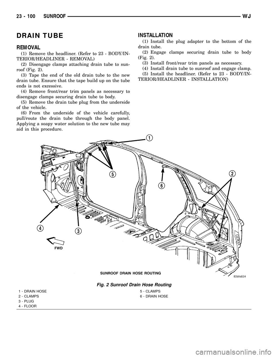
(2) Disengage clamps attaching drain tube to sun-
roof (Fig. 2).
(3) Tape the end of the old drain tube to the new
drain tube. Ensure that the tape build up on the tube
ends is not excessive.
(4) Remove front/rear trim panels as necessary to
disengage clamps securing drain tube to body.
(5) Remove the drain tube plug from the underside
of the vehicle.
(6) From the underside of the vehicle carefully,
pull/route the drain tube through the body panel.
Applying a soapy water solution to the new tube may
aid in this procedure.
INSTALLATION
(1) Install the plug adapter to the bottom of the
drain tube.
(2) Engage clamps securing drain tube to body
(Fig. 2).
(3) Install front/rear trim panels as necessary.
(4) Install drain tube to sunroof and engage clamp.
(5) Install the headliner. (Refer to 23 - BODY/IN-
TERIOR/HEADLINER - INSTALLATION)
Fig. 2 Sunroof Drain Hose Routing
1 - DRAIN HOSE
2 - CLAMPS
3 - PLUG
4 - FLOOR5 - CLAMPS
6 - DRAIN HOSE
23 - 100 SUNROOFWJ
Page 1977 of 2199

(6) Push sunshade down until the sunshade clears
the glass then move sunshade rearward behind the
glass panel.
HOUSING ASSEMBLY
REMOVAL
(1) Move glass panel to the fully closed position.
(2) Disconnect battery negative cable.
(3) Recline both front seats.
(4) Remove headliner. (Refer to 23 - BODY/INTE-
RIOR/HEADLINER - REMOVAL)
(5) Disconnect the drain tubes from sunroof hous-
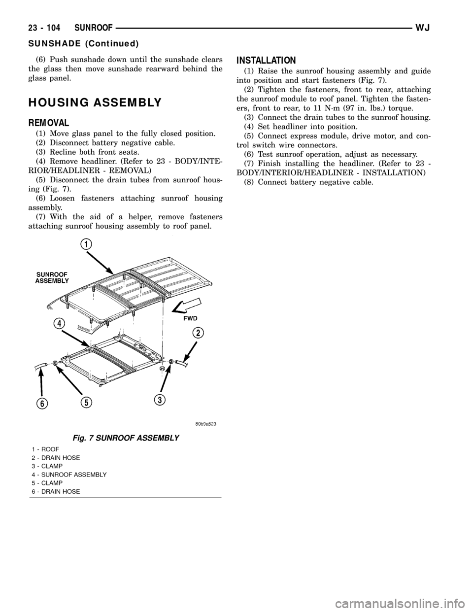
ing (Fig. 7).
(6) Loosen fasteners attaching sunroof housing
assembly.
(7) With the aid of a helper, remove fasteners
attaching sunroof housing assembly to roof panel.
INSTALLATION
(1) Raise the sunroof housing assembly and guide
into position and start fasteners (Fig. 7).
(2) Tighten the fasteners, front to rear, attaching
the sunroof module to roof panel. Tighten the fasten-
ers, front to rear, to 11 N´m (97 in. lbs.) torque.
(3) Connect the drain tubes to the sunroof housing.
(4) Set headliner into position.
(5) Connect express module, drive motor, and con-
trol switch wire connectors.
(6) Test sunroof operation, adjust as necessary.
(7) Finish installing the headliner. (Refer to 23 -
BODY/INTERIOR/HEADLINER - INSTALLATION)
(8) Connect battery negative cable.
Fig. 7 SUNROOF ASSEMBLY
1 - ROOF
2 - DRAIN HOSE
3 - CLAMP
4 - SUNROOF ASSEMBLY
5 - CLAMP
6 - DRAIN HOSE
23 - 104 SUNROOFWJ
SUNSHADE (Continued)
Page 1985 of 2199
NOTE:
All measurements are in mm.
LOCATION DESCRIPTION GAP FLUSH
A Front Door to Windshield Pillar N/A 3.0 +/- 1.0
B Front Door Header to Aperture 6.0 +/- 1.0 1.0 +/- 1.5
C Front Door to Rear Door 5.0 +/- 1.0 0.0 +/- 1.0
D Front Door to Aperture at Sill 7.0 +/- 1.5 N/A
E Front Door to Fender 5.0 +/- 1.0 0.5 +/- 1.0
F Hood to Fender 5.0 +/- 1.0 0.0 +/- 1.0
G Headlamp to Fender 5.0 +/- 2.0 3.0 +/- 2.0
H Headlamp to Grille 5.5 +/- 2.0 0.0 +/- 2.0
I Grille to Headlamp N/A 0.0 +/- 1.0
J Grille to Hood 10.0 +/- 2.0 0.8 +/- 2.0
K Front Fascia to Fender Net + 1.0 - 0.0 3.0 +/- 3.0
L Fuel Filler Door to Bodyside 3.0 +/- 0.75 0.5 +/- 0.75
Fig. 1 FRONT VIEW
WJBODY STRUCTURE 23 - 113
GAP AND FLUSH (Continued)
Page 1986 of 2199
NOTE:
All measurements are in mm.
LOCATION DESCRIPTION GAP FLUSH
M Rear Door to Quarter Panel 5.0 +/- 1.0 0.0 +/- 1.0
N Aperture to Rear Fascia Net to 1.0 3.0 +/- 2.0
O Taillamp to Quarter Panel 2.0 +/- 1.0 3.0 +/- 1.5
Q Liftgate to Fascia 10.0 +/- 3.0 N/A
R Liftgate to Aperture 5.0 +/- 1.5 1.0 +/- 1.0
S Liftgate to Roof 11.0 +/- 1.5 1.0 +/- 1.0
T Rear Door Header to Aperture 6.0 +/- 1.0 1.0 +/- 1.5
Fig. 2 REAR VIEW
WJBODY STRUCTURE 23 - 113
GAP AND FLUSH (Continued)
Page 2010 of 2199
STUCTURAL ADHESIVE
LOCATIONS
SPECIFICATIONS - STRUCTURAL ADHESIVE
LOCATIONS
INDEX
DESCRIPTION FIGURE
COWL PLENUM 28
DASH PANEL AND FRONT FLOOR PAN 29
PLENUM AND WINDSHIELD WIPER MOUNTING 30
FRONT FLOOR PAN AND SILLS 31
FRONT AND CENTER FLOOR PAN 32
FRONT PAN AND INNER BODY SIDE APERTURE 33
REAR SEAT CROSSMEMBER 34
REAR INNER WHEELHOUSE 35
FLOOR PAN AND SILL ASSEMBLY 36
FLOOR PAN 37
REAR INNER WHEELHOUSE AND REAR FLOOR PAN 38
RIGHT INNER BODYSIDE APERTURE 39
BODY SIDE INNER PANEL AND WHEELHOUSE 40
BODY SIDE OUTER PANEL AND REAR WHEELHOUSE OUTER PANEL 41
D-PILLAR AND FUEL FILLER GUSSETS 42
LIFTGATE 43
TAILLAMP MOUNTING PANEL 44
TAILLAMP 45
REAR INNER CROSSMEMBER 46
ROOF BOWS 47
REAR LOWER HEADER 48
WJBODY STRUCTURE 23 - 137
Page 2022 of 2199
Fig. 44 TAILLAMP MOUNTING PANEL
WJBODY STRUCTURE 23 - 149
STUCTURAL ADHESIVE LOCATIONS (Continued)