2003 JEEP GRAND CHEROKEE lamp
[x] Cancel search: lampPage 1505 of 2199
SPECIFICATIONS
TORQUE CHART
TORQUE SPECIFICATIONS
DESCRIPTION N´m Ft. Lbs. In. Lbs.
Pitman Arm
Shaft Nut251 185 Ð
Drag Link
Pitman Arm Nut88 65 Ð
Drag Link
Knuckle Nut47 35 Ð
Drag Link
Clamp Nuts41 30 Ð
Tie Rod
Knuckle Nut47 35 Ð
Tie Rod
Clamp Nuts41 30 Ð
Steering Damper
Axle Bolt88 65 Ð
Steering Damper
Tie Rod Nut41 30 Ð
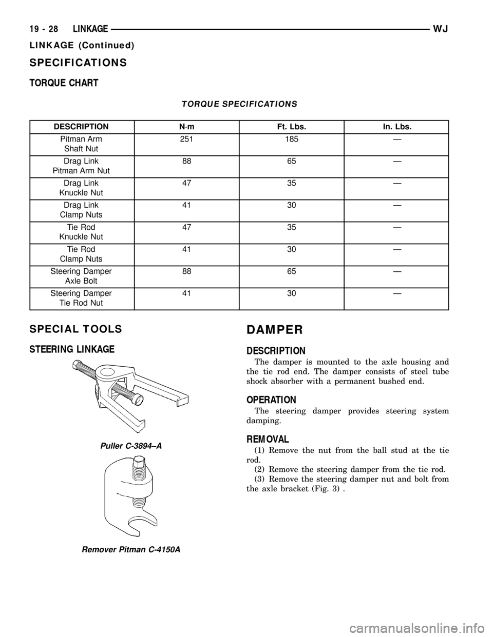
SPECIAL TOOLS
STEERING LINKAGEDAMPER
DESCRIPTION
The damper is mounted to the axle housing and
the tie rod end. The damper consists of steel tube
shock absorber with a permanent bushed end.
OPERATION
The steering damper provides steering system
damping.
REMOVAL
(1) Remove the nut from the ball stud at the tie
rod.
(2) Remove the steering damper from the tie rod.
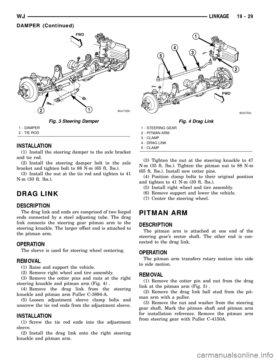
(3) Remove the steering damper nut and bolt from
the axle bracket (Fig. 3) .Puller C-3894±A
Remover Pitman C-4150A
19 - 28 LINKAGEWJ
LINKAGE (Continued)
Page 1506 of 2199
INSTALLATION
(1) Install the steering damper to the axle bracket
and tie rod.
(2) Install the steering damper bolt in the axle
bracket and tighten bolt to 88 N´m (65 ft. lbs.).
(3) Install the nut at the tie rod and tighten to 41
N´m (30 ft. lbs.).
DRAG LINK
DESCRIPTION
The drag link and ends are comprised of two forged
ends connected by a steel adjusting tube. The drag
link connects the steering gear pitman arm to the
steering knuckle. The larger offset end is attached to
the pitman arm.
OPERATION
The sleeve is used for steering wheel centering.
REMOVAL
(1) Raise and support the vehicle.
(2) Remove right wheel and tire assembly.
(3) Remove the cotter pins and nuts at the right
steering knuckle and pitman arm (Fig. 4) .
(4) Remove the drag link from the steering
knuckle and pitman arm Puller C-3894-A.
(5) Loosen adjustment sleeve clamp bolts and
unscrew the tie rod ends from the adjustment sleeve.
INSTALLATION
(1) Screw the tie rod ends into the adjustment
sleeve.
(2) Install the drag link onto the right steering
knuckle and pitman arm.(3) Tighten the nut at the steering knuckle to 47
N´m (35 ft. lbs.). Tighten the pitman nut to 88 N´m
(65 ft. lbs.). Install new cotter pins.
(4) Position clamp bolts to their original position
and tighten to 41 N´m (30 ft. lbs.).
(5) Install right wheel and tire assembly.
(6) Remove support and lower the vehicle.
(7) Center the steering wheel.
PITMAN ARM
DESCRIPTION
The pitman arm is attached at one end of the
steering gear's sector shaft. The other end is con-
nected to the drag link.
OPERATION
The pitman arm transfers rotary motion into side
to side motion.
REMOVAL
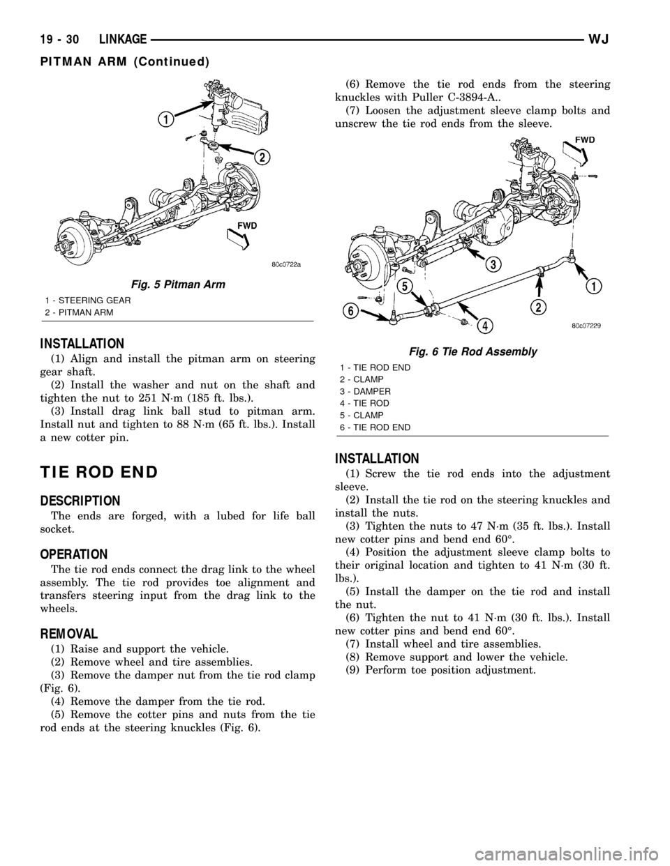
(1) Remove the cotter pin and nut from the drag
link at the pitman arm (Fig. 5) .
(2) Remove the drag link ball stud from the pit-
man arm with a puller.
(3) Remove the nut and washer from the steering
gear shaft. Mark the pitman shaft and pitman arm
for installation reference. Remove the pitman arm
from steering gear with Puller C-4150A.
Fig. 3 Steering Damper
1 - DAMPER
2 - TIE ROD
Fig. 4 Drag Link
1 - STEERING GEAR
2 - PITMAN ARM
3 - CLAMP
4 - DRAG LINK
5 - CLAMP
WJLINKAGE 19 - 29
DAMPER (Continued)
Page 1507 of 2199
INSTALLATION
(1) Align and install the pitman arm on steering
gear shaft.
(2) Install the washer and nut on the shaft and
tighten the nut to 251 N´m (185 ft. lbs.).
(3) Install drag link ball stud to pitman arm.
Install nut and tighten to 88 N´m (65 ft. lbs.). Install
a new cotter pin.
TIE ROD END
DESCRIPTION
The ends are forged, with a lubed for life ball
socket.
OPERATION
The tie rod ends connect the drag link to the wheel
assembly. The tie rod provides toe alignment and
transfers steering input from the drag link to the
wheels.
REMOVAL
(1) Raise and support the vehicle.
(2) Remove wheel and tire assemblies.
(3) Remove the damper nut from the tie rod clamp
(Fig. 6).
(4) Remove the damper from the tie rod.
(5) Remove the cotter pins and nuts from the tie
rod ends at the steering knuckles (Fig. 6).(6) Remove the tie rod ends from the steering
knuckles with Puller C-3894-A..
(7) Loosen the adjustment sleeve clamp bolts and
unscrew the tie rod ends from the sleeve.
INSTALLATION
(1) Screw the tie rod ends into the adjustment
sleeve.
(2) Install the tie rod on the steering knuckles and
install the nuts.
(3) Tighten the nuts to 47 N´m (35 ft. lbs.). Install
new cotter pins and bend end 60É.
(4) Position the adjustment sleeve clamp bolts to
their original location and tighten to 41 N´m (30 ft.
lbs.).
(5) Install the damper on the tie rod and install
the nut.
(6) Tighten the nut to 41 N´m (30 ft. lbs.). Install
new cotter pins and bend end 60É.
(7) Install wheel and tire assemblies.
(8) Remove support and lower the vehicle.
(9) Perform toe position adjustment.
Fig. 5 Pitman Arm
1 - STEERING GEAR
2 - PITMAN ARM
Fig. 6 Tie Rod Assembly
1 - TIE ROD END
2 - CLAMP
3 - DAMPER
4 - TIE ROD
5 - CLAMP
6 - TIE ROD END
19 - 30 LINKAGEWJ
PITMAN ARM (Continued)
Page 1514 of 2199
INSTALLATION
(1) Position and install the power steering cooler
to the vehicle.
(2) Install the three mounting bracket bolts (Fig.
6).
(3) Reconnect the upper hose at cooler (Fig. 6).
(4) Reconnect the lower hose at cooler (Fig. 6).
(5) Connect negative battery cable to battery.
(6) Refill the power steering fluid and bleed the
system,(Refer to 19 - STEERING/PUMP - STAN-
DARD PROCEDURE).
(7) Start engine and check for leaks.
(8) Install the grille opening reinforcement panel
(9) Install the front fascia grille,(Refer to 13 -
FRAMES & BUMPERS/BUMPERS/FRONT FASCIA
- INSTALLATION).
HOSES - 4.0L
DESCRIPTION
DESCRIPTION - PRESSURE LINE
The hose consists of two metal ends and rubber
center section that contains a tuning cable. The
pump end uses a quick connect fitting. Lubircation
must be used on the quick connect nut and o-ring
when installing.
DESCRIPTION - RETURN LINE
Power steering return line is a hose which is
clamped at the pump and the gear.
OPERATION
OPERATION - PRESSURE LINE
Power steering pressure line, is used to transfer
high pressure power steering fluid, from the power
steering pump to the power steering gear on the
4.0L. The 4.7L power steering pressure line, is used
to transfer high pressure power steering fluid, from
the power steering pump to the engine cooling fan
and the steering gear.
OPERATION - RETURN LINE
Power steering return line, is used to transfer low
pressure power steering fluid, from the power steer-
ing gear to the power steering pump.
REMOVAL
(1) Drain the power steering fluid from the reser-
voir.
(2) Remove the air box,(Refer to 9 - ENGINE/AIR
INTAKE SYSTEM/AIR CLEANER HOUSING -
REMOVAL).
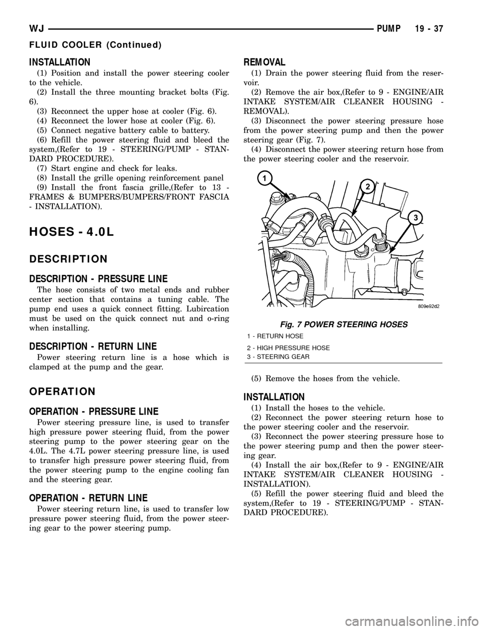
(3) Disconnect the power steering pressure hose
from the power steering pump and then the power
steering gear (Fig. 7).
(4) Disconnect the power steering return hose from
the power steering cooler and the reservoir.
(5) Remove the hoses from the vehicle.
INSTALLATION
(1) Install the hoses to the vehicle.
(2) Reconnect the power steering return hose to
the power steering cooler and the reservoir.
(3) Reconnect the power steering pressure hose to
the power steering pump and then the power steer-
ing gear.
(4) Install the air box,(Refer to 9 - ENGINE/AIR
INTAKE SYSTEM/AIR CLEANER HOUSING -
INSTALLATION).
(5) Refill the power steering fluid and bleed the
system,(Refer to 19 - STEERING/PUMP - STAN-
DARD PROCEDURE).
Fig. 7 POWER STEERING HOSES
1 - RETURN HOSE
2 - HIGH PRESSURE HOSE
3 - STEERING GEAR
WJPUMP 19 - 37
FLUID COOLER (Continued)
Page 1515 of 2199
HOSES - 4.7L
DESCRIPTION
DESCRIPTION - 1/2º PRESSURE HOSE
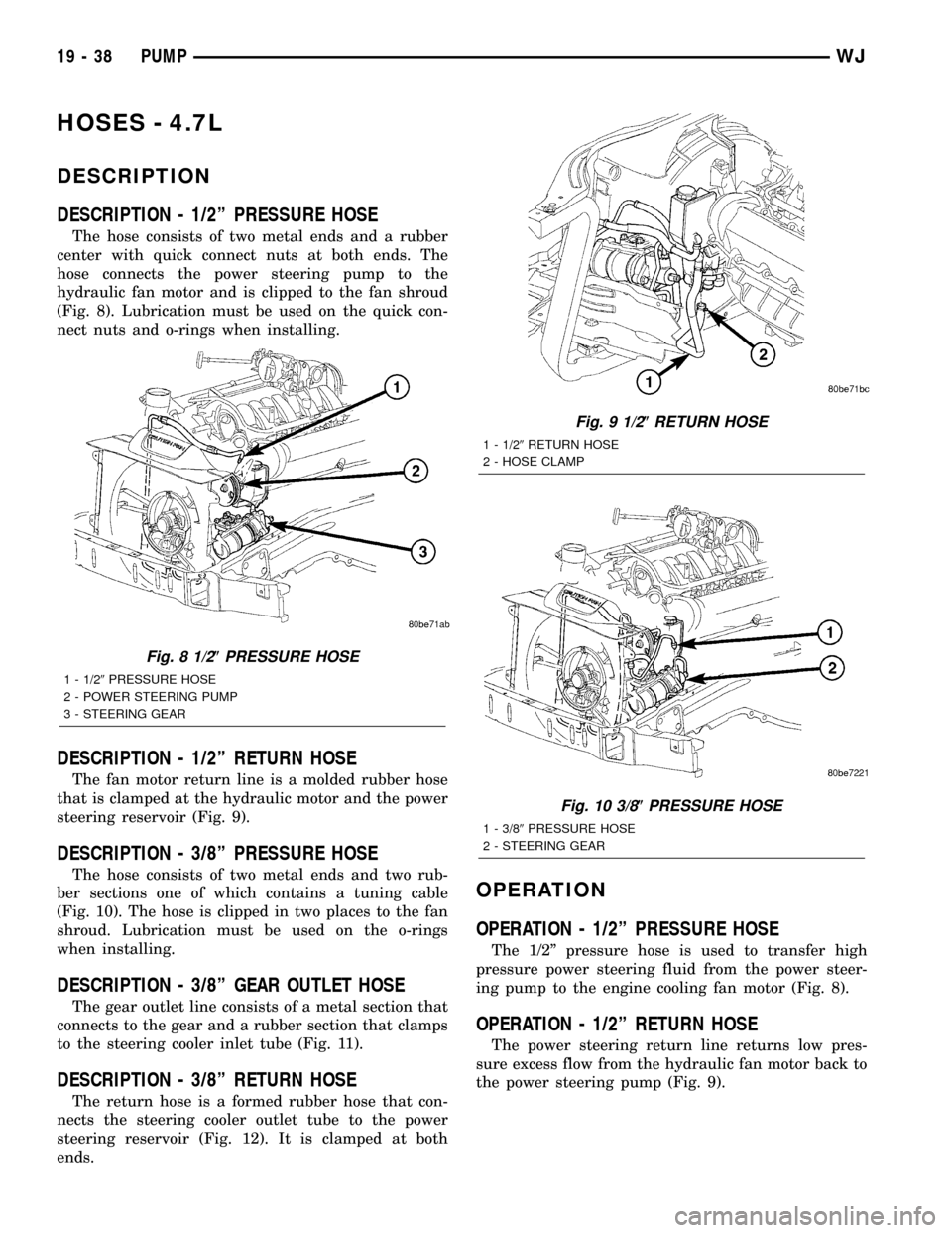
The hose consists of two metal ends and a rubber
center with quick connect nuts at both ends. The
hose connects the power steering pump to the
hydraulic fan motor and is clipped to the fan shroud
(Fig. 8). Lubrication must be used on the quick con-
nect nuts and o-rings when installing.
DESCRIPTION - 1/2º RETURN HOSE
The fan motor return line is a molded rubber hose
that is clamped at the hydraulic motor and the power
steering reservoir (Fig. 9).
DESCRIPTION - 3/8º PRESSURE HOSE
The hose consists of two metal ends and two rub-
ber sections one of which contains a tuning cable
(Fig. 10). The hose is clipped in two places to the fan
shroud. Lubrication must be used on the o-rings
when installing.
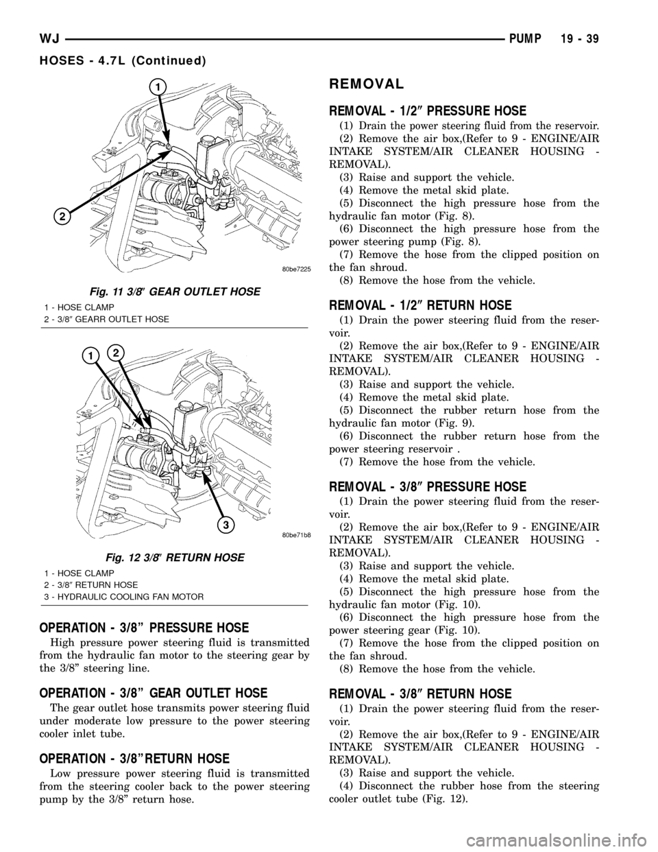
DESCRIPTION - 3/8º GEAR OUTLET HOSE
The gear outlet line consists of a metal section that
connects to the gear and a rubber section that clamps
to the steering cooler inlet tube (Fig. 11).
DESCRIPTION - 3/8º RETURN HOSE
The return hose is a formed rubber hose that con-
nects the steering cooler outlet tube to the power
steering reservoir (Fig. 12). It is clamped at both
ends.
OPERATION
OPERATION - 1/2º PRESSURE HOSE
The 1/2º pressure hose is used to transfer high
pressure power steering fluid from the power steer-
ing pump to the engine cooling fan motor (Fig. 8).
OPERATION - 1/2º RETURN HOSE
The power steering return line returns low pres-
sure excess flow from the hydraulic fan motor back to
the power steering pump (Fig. 9).
Fig. 8 1/2(PRESSURE HOSE
1 - 1/29PRESSURE HOSE
2 - POWER STEERING PUMP
3 - STEERING GEAR
Fig. 9 1/2(RETURN HOSE
1 - 1/29RETURN HOSE
2 - HOSE CLAMP
Fig. 10 3/8(PRESSURE HOSE
1 - 3/89PRESSURE HOSE
2 - STEERING GEAR
19 - 38 PUMPWJ
Page 1516 of 2199
OPERATION - 3/8º PRESSURE HOSE
High pressure power steering fluid is transmitted
from the hydraulic fan motor to the steering gear by
the 3/8º steering line.
OPERATION - 3/8º GEAR OUTLET HOSE
The gear outlet hose transmits power steering fluid
under moderate low pressure to the power steering
cooler inlet tube.
OPERATION - 3/8ºRETURN HOSE
Low pressure power steering fluid is transmitted
from the steering cooler back to the power steering
pump by the 3/8º return hose.
REMOVAL
REMOVAL - 1/2(PRESSURE HOSE
(1)Drain the power steering fluid from the reservoir.
(2) Remove the air box,(Refer to 9 - ENGINE/AIR
INTAKE SYSTEM/AIR CLEANER HOUSING -
REMOVAL).
(3) Raise and support the vehicle.
(4) Remove the metal skid plate.
(5) Disconnect the high pressure hose from the
hydraulic fan motor (Fig. 8).
(6) Disconnect the high pressure hose from the
power steering pump (Fig. 8).
(7) Remove the hose from the clipped position on
the fan shroud.
(8) Remove the hose from the vehicle.
REMOVAL - 1/2(RETURN HOSE
(1) Drain the power steering fluid from the reser-
voir.
(2) Remove the air box,(Refer to 9 - ENGINE/AIR
INTAKE SYSTEM/AIR CLEANER HOUSING -
REMOVAL).
(3) Raise and support the vehicle.
(4) Remove the metal skid plate.
(5) Disconnect the rubber return hose from the
hydraulic fan motor (Fig. 9).
(6) Disconnect the rubber return hose from the
power steering reservoir .
(7) Remove the hose from the vehicle.
REMOVAL - 3/8(PRESSURE HOSE
(1) Drain the power steering fluid from the reser-
voir.
(2) Remove the air box,(Refer to 9 - ENGINE/AIR
INTAKE SYSTEM/AIR CLEANER HOUSING -
REMOVAL).
(3) Raise and support the vehicle.
(4) Remove the metal skid plate.
(5) Disconnect the high pressure hose from the
hydraulic fan motor (Fig. 10).
(6) Disconnect the high pressure hose from the
power steering gear (Fig. 10).
(7) Remove the hose from the clipped position on
the fan shroud.
(8) Remove the hose from the vehicle.
REMOVAL - 3/8(RETURN HOSE
(1) Drain the power steering fluid from the reser-
voir.
(2) Remove the air box,(Refer to 9 - ENGINE/AIR
INTAKE SYSTEM/AIR CLEANER HOUSING -
REMOVAL).
(3) Raise and support the vehicle.
(4) Disconnect the rubber hose from the steering
cooler outlet tube (Fig. 12).
Fig. 11 3/8(GEAR OUTLET HOSE
1 - HOSE CLAMP
2 - 3/89GEARR OUTLET HOSE
Fig. 12 3/8(RETURN HOSE
1 - HOSE CLAMP
2 - 3/89RETURN HOSE
3 - HYDRAULIC COOLING FAN MOTOR
WJPUMP 19 - 39
HOSES - 4.7L (Continued)
Page 1517 of 2199
(5) Disconnect the rubber hose from the power
steering reservoir (Fig. 12).
(6) Remove the hose from the vehicle.
REMOVAL - 3/8(GEAR OUTLET HOSE
(1) Drain the power steering fluid from the reser-
voir.
(2) Remove the air box,(Refer to 9 - ENGINE/AIR
INTAKE SYSTEM/AIR CLEANER HOUSING -
REMOVAL).
(3) Raise and support the vehicle.
(4) Disconnect the rubber hose from the steering
cooler inlet tube (Fig. 11).
(5) Disconnect the metal tube from the power
steering gear (Fig. 11).
(6) Remove the hose from the vehicle.
REMOVAL - INLET COOLER HOSE
(1) Disconnect negative battery cable at battery.
(2) Drain the power steering fluid out of the reser-
voir.
(3) Remove the air box,(Refer to 9 - ENGINE/AIR
INTAKE SYSTEM/AIR CLEANER HOUSING -
REMOVAL).
(4) Remove the front fascia grille assembly,(Refer
to 13 - FRAMES & BUMPERS/BUMPERS/FRONT
FASCIA - REMOVAL).
(5) Remove the grille opening reinforcement panel
(6) Place a drain pan under the cooler.
(7) Disconnect the lower hose at cooler (Fig. 6).
(8) Disconnect the cooler hose at the gear.
(9) Remove the bracket holding the cooler hoses
(Fig. 13).
(10) Remove the cooler hose from the vehicle.
REMOVAL - OUTLET COOLER HOSE
(1) Disconnect negative battery cable at battery.
(2) Drain the power steering fluid out of the reser-
voir.
(3) Remove the air box,(Refer to 9 - ENGINE/AIR
INTAKE SYSTEM/AIR CLEANER HOUSING -
REMOVAL).
(4) Remove the front fascia grille assembly,(Refer
to 13 - FRAMES & BUMPERS/BUMPERS/FRONT
FASCIA - REMOVAL).
(5) Remove the grille opening reinforcement panel
(6) Place a drain pan under the cooler.
(7) Disconnect the upper hose at cooler (Fig. 6).
(8) Disconnect the cooler hose at the reservoir.
(9) Remove the bracket holding the cooler hoses
(Fig. 13).
(10) Remove the cooler hose from the vehicle.
INSTALLATION
INSTALLATION - 1/2(PRESSURE HOSE
NOTE: Lubrication and a new o-ring must be used
when reinstalling.
(1) Install the hoses to the vehicle.
(2) Reconnect the high pressure hose to the power
steering pump (Fig. 8) Tighten the hose to 22.5 N´m
(17 ft.lbs.).
(3) Reconnect the high pressure hose to the
hydraulic fan motor (Fig. 8) Tighten the hose to 22.5
N´m (17 ft.lbs.).
(4) Install the hose to the clipped position on the
fan shroud.
(5) Install the metal skid plate.
(6) Install the air box,(Refer to 9 - ENGINE/AIR
INTAKE SYSTEM/AIR CLEANER HOUSING -
INSTALLATION).
(7) Refill the power steering fluid and bleed the
system,(Refer to 19 - STEERING/PUMP - STAN-
DARD PROCEDURE).
INSTALLATION - 1/2(RETURN HOSE
(1) Install the hoses to the vehicle.
(2) Reconnect the rubber return hose to the power
steering reservoir (Fig. 9) Tighten the hose clamp.
(3) Reconnect the rubber return hose to the
hydraulic fan motor (Fig. 9) Tighten the hose.
(4) Install the metal skid plate.
(5) Install the air box,(Refer to 9 - ENGINE/AIR
INTAKE SYSTEM/AIR CLEANER HOUSING -
INSTALLATION).
(6) Refill the power steering fluid and bleed the
system,(Refer to 19 - STEERING/PUMP - STAN-
DARD PROCEDURE).
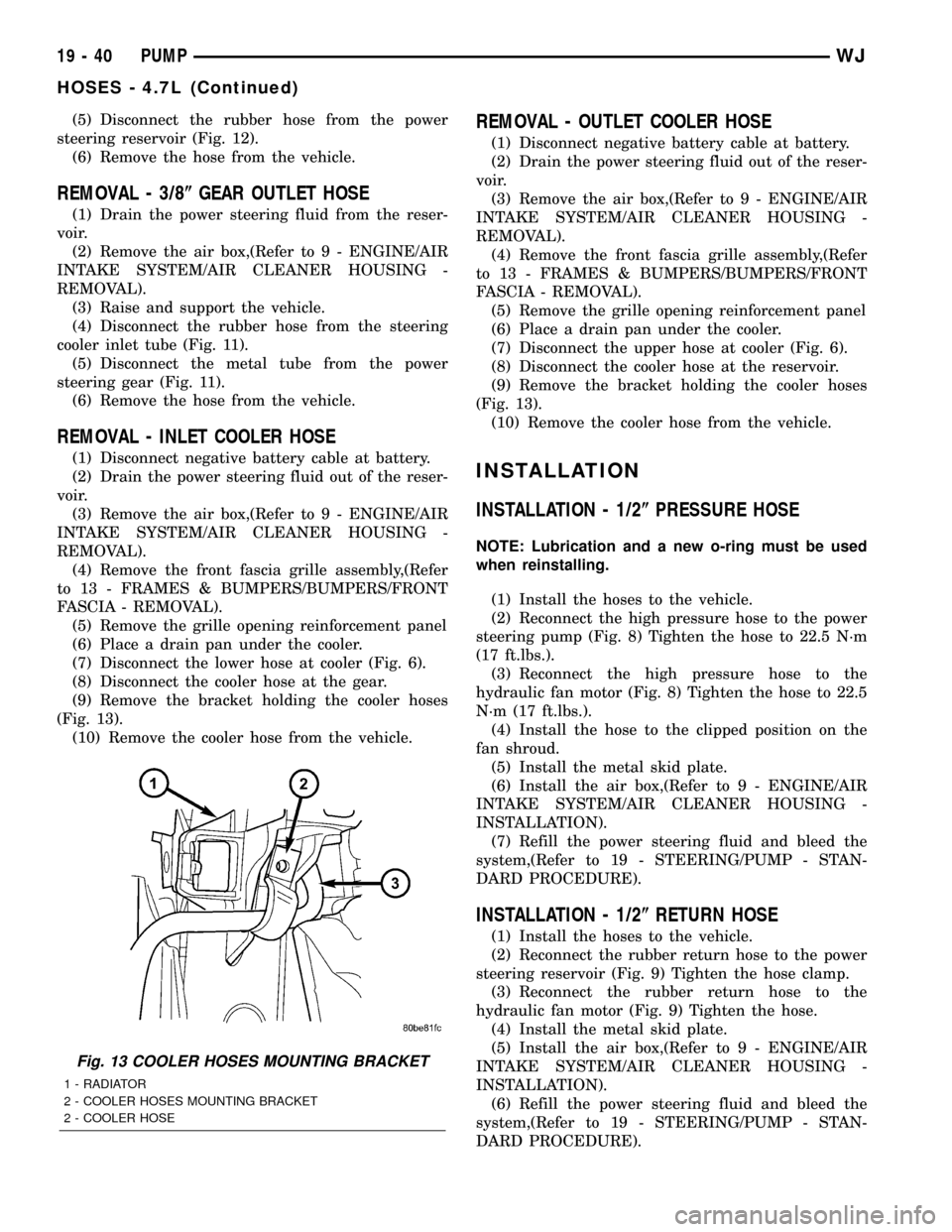
Fig. 13 COOLER HOSES MOUNTING BRACKET
1 - RADIATOR
2 - COOLER HOSES MOUNTING BRACKET
2 - COOLER HOSE
19 - 40 PUMPWJ
HOSES - 4.7L (Continued)
Page 1518 of 2199
INSTALLATION - 3/8(PRESSURE HOSE
NOTE: Lubrication and a new o-ring must be used
when reinstalling.
(1) Install the hoses to the vehicle.
(2) Reconnect the high pressure hose to the
hydraulic fan motor (Fig. 10) Tighten the hose to
22.5 N´m (17 ft.lbs.).
(3) Reconnect the high pressure hose to the power
steering gear (Fig. 10) Tighten the hose to 22.5 N´m
(17 ft.lbs.).
(4) Install the hose to the clipped position on the
fan shroud.
(5) Install the metal skid plate.
(6) Install the air box,(Refer to 9 - ENGINE/AIR
INTAKE SYSTEM/AIR CLEANER HOUSING -
INSTALLATION).
(7) Refill the power steering fluid and bleed the
system,(Refer to 19 - STEERING/PUMP - STAN-
DARD PROCEDURE).
INSTALLATION - 3/8(RETURN HOSE
(1) Install the hoses to the vehicle.
(2) Reconnect the rubber hose to the steering
cooler outlet tube (Fig. 12) Tighten the hose clamp.
(3) Reconnect the rubber hose to the power steer-
ing reservoir (Fig. 12) Tighten the hose clamp.
(4) Install the air box,(Refer to 9 - ENGINE/AIR
INTAKE SYSTEM/AIR CLEANER HOUSING -
INSTALLATION).
(5) Refill the power steering fluid and bleed the
system,(Refer to 19 - STEERING/PUMP - STAN-
DARD PROCEDURE).
INSTALLATION - 3/8(GEAR OUTLET HOSE
NOTE: Lubrication and a new o-ring must be used
when reinstalling.
(1) Install the hoses to the vehicle.
(2) Reconnect the rubber hose to the steering
cooler inlet tube (Fig. 11) Tighten the hose clamp.
(3)
Reconnect the metal tube to the power steering
gear (Fig. 11) Tighten the hose to 22.5 N´m (17 ft.lbs.).
(4) Install the air box,(Refer to 9 - ENGINE/AIR
INTAKE SYSTEM/AIR CLEANER HOUSING -
INSTALLATION).
(5) Refill the power steering fluid and bleed the
system,(Refer to 19 - STEERING/PUMP - STAN-
DARD PROCEDURE).
INSTALLATION - INLET COOLER HOSE
(1) Install the cooler hose to the vehicle.
(2) Reconnect the cooler hose at the gear.
(3) Reconnect the lower hose at cooler (Fig. 6).
Tighten the hose to 22.5 N´m (17 ft.lbs.)
(4) Install the bracket holding the cooler hoses
(Fig. 13).(5) Install the air box,(Refer to 9 - ENGINE/AIR
INTAKE SYSTEM/AIR CLEANER HOUSING -
INSTALLATION).
(6) Install the grille opening reinforcement panel
(7) Install the front fascia grille assembly, (Refer to
13 - FRAMES & BUMPERS/BUMPERS/FRONT
FASCIA - INSTALLATION).
(8) Reconnect negative battery cable at battery.
(9) Refill the power steering fluid and bleed the
system,(Refer to 19 - STEERING/PUMP - STAN-
DARD PROCEDURE).
INSTALLATION - OUTLET COOLER HOSE
(1) Install the cooler hose to the vehicle.
(2) Reconnect the cooler hose at the reservoir.
(3) Reconnect the upper hose at the cooler (Fig. 6).
Tighten the hose to 22.5 N´m (17 ft. lbs.)
(4) Install the bracket holding the cooler hoses
(Fig. 13). Tighten the bracket to 22.5 N´m (17 ft. lbs.)
(5) Install the air box,(Refer to 9 - ENGINE/AIR
INTAKE SYSTEM/AIR CLEANER HOUSING -
INSTALLATION).
(6) Install the grille opening reinforcement panel
(7) Install the front fascia grille assembly, (Refer to
13 - FRAMES & BUMPERS/BUMPERS/FRONT
FASCIA - INSTALLATION).
(8) Reconnect negative battery cable at battery.
(9) Refill the power steering fluid and bleed the
system,(Refer to 19 - STEERING/PUMP - STAN-
DARD PROCEDURE).
PULLEY
DESCRIPTION
POWER STEERING PUMP PULLEY - 3.1L
DIESEL
To service the power steering pump pulley on the
3.1L turbo diesel engine. Refer to the power steering
pump removal and installation procedure in this
group. The pulley must be removed to service the
pump assembly. Detailed instructions are provided in
the pump procedure.
REMOVAL
CAUTION: On vehicles equipped with the 4.0L or
4.7L, Do not reuse the old power steering pump
pulley it is not intended for reuse. A new pulley
must be installed if removed.
(1) Remove pump assembly.
(2) Remove pulley from pump with Puller C-4333
or equivalent puller (Fig. 14).
WJPUMP 19 - 41
HOSES - 4.7L (Continued)