However, evaporator capacity used to reduce the
amount of moisture in the air is not wasted. Wring-
ing some of the moisture out of the air entering the
vehicle adds to the comfort of the passengers.
Although, an owner may expect too much from their
air conditioning system on humid days. A perfor-
mance test is the best way to determine whether the
system is performing up to standard. This test also
provides valuable clues as to the possible cause of
trouble with the air conditioning system.
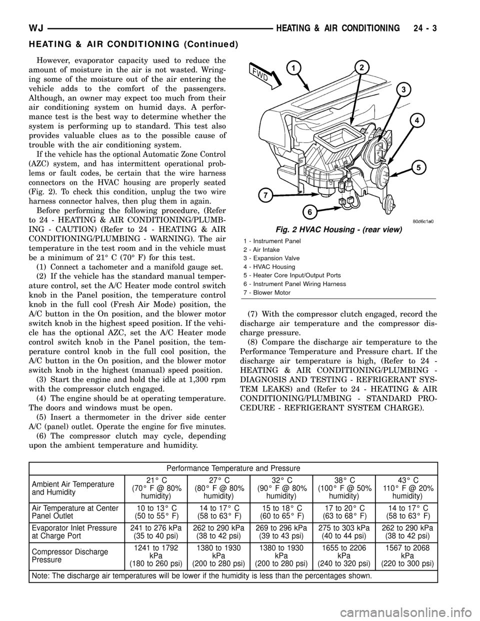
If the vehicle has the optional Automatic Zone Control
(AZC) system, and has intermittent operational prob-
lems or fault codes, be certain that the wire harness
connectors on the HVAC housing are properly seated
(Fig. 2). To check this condition, unplug the two wire
harness connector halves, then plug them in again.
Before performing the following procedure, (Refer
to 24 - HEATING & AIR CONDITIONING/PLUMB-
ING - CAUTION) (Refer to 24 - HEATING & AIR
CONDITIONING/PLUMBING - WARNING). The air
temperature in the test room and in the vehicle must
be a minimum of 21É C (70É F) for this test.
(1)
Connect a tachometer and a manifold gauge set.
(2) If the vehicle has the standard manual temper-
ature control, set the A/C Heater mode control switch
knob in the Panel position, the temperature control
knob in the full cool (Fresh Air Mode) position, the
A/C button in the On position, and the blower motor
switch knob in the highest speed position. If the vehi-
cle has the optional AZC, set the A/C Heater mode
control switch knob in the Panel position, the tem-
perature control knob in the full cool position, the
A/C button in the On position, and the blower motor
switch knob in the highest (manual) speed position.
(3) Start the engine and hold the idle at 1,300 rpm
with the compressor clutch engaged.
(4) The engine should be at operating temperature.
The doors and windows must be open.
(5)
Insert a thermometer in the driver side center
A/C (panel) outlet. Operate the engine for five minutes.
(6) The compressor clutch may cycle, depending
upon the ambient temperature and humidity.(7) With the compressor clutch engaged, record the
discharge air temperature and the compressor dis-
charge pressure.
(8) Compare the discharge air temperature to the
Performance Temperature and Pressure chart. If the
discharge air temperature is high, (Refer to 24 -
HEATING & AIR CONDITIONING/PLUMBING -
DIAGNOSIS AND TESTING - REFRIGERANT SYS-
TEM LEAKS) and (Refer to 24 - HEATING & AIR
CONDITIONING/PLUMBING - STANDARD PRO-
CEDURE - REFRIGERANT SYSTEM CHARGE).
Performance Temperature and Pressure
Ambient Air Temperature
and Humidity21É C
(70É F @ 80%
humidity)27É C
(80É F @ 80%
humidity)32É C
(90É F @ 80%
humidity)38É C
(100ÉF@50%
humidity)43É C
110É F @ 20%
humidity)
Air Temperature at Center
Panel Outlet10 to 13É C
(50 to 55É F)14 to 17É C
(58 to 63É F)15 to 18É C
(60 to 65É F)17 to 20É C
(63 to 68É F)14 to 17É C
(58 to 63É F)
Evaporator Inlet Pressure
at Charge Port241 to 276 kPa
(35 to 40 psi)262 to 290 kPa
(38 to 42 psi)269 to 296 kPa
(39 to 43 psi)275 to 303 kPa
(40 to 44 psi)262 to 290 kPa
(38 to 42 psi)
Compressor Discharge
Pressure1241 to 1792
kPa
(180 to 260 psi)1380 to 1930
kPa
(200 to 280 psi)1380 to 1930
kPa
(200 to 280 psi)1655 to 2206
kPa
(240 to 320 psi)1567 to 2068
kPa
(220 to 300 psi)
Note: The discharge air temperatures will be lower if the humidity is less than the percentages shown.
Fig. 2 HVAC Housing - (rear view)
1 - Instrument Panel
2 - Air Intake
3 - Expansion Valve
4 - HVAC Housing
5 - Heater Core Input/Output Ports
6 - Instrument Panel Wiring Harness
7 - Blower Motor
WJHEATING & AIR CONDITIONING 24 - 3
HEATING & AIR CONDITIONING (Continued)
HVAC HOUSING
REMOVAL
The HVAC housing assembly must be removed
from the vehicle and the two halves of the housing
separated for service access of the heater core, evap-
orator coil, blend door(s), and each of the various
mode doors.
WARNING: ON VEHICLES EQUIPPED WITH AIR-
BAGS, DISABLE THE AIRBAG SYSTEM BEFORE
ATTEMPTING ANY STEERING WHEEL, STEERING
COLUMN, OR INSTRUMENT PANEL COMPONENT
DIAGNOSIS OR SERVICE. DISCONNECT AND ISO-
LATE THE BATTERY NEGATIVE (GROUND) CABLE,
THEN WAIT TWO MINUTES FOR THE AIRBAG SYS-
TEM CAPACITOR TO DISCHARGE BEFORE PER-
FORMING FURTHER DIAGNOSIS OR SERVICE. THIS
IS THE ONLY SURE WAY TO DISABLE THE AIRBAG
SYSTEM. FAILURE TO TAKE THE PROPER PRE-
CAUTIONS COULD RESULT IN AN ACCIDENTAL
AIRBAG DEPLOYMENT AND POSSIBLE PERSONAL
INJURY.
WARNING: REVIEW THE WARNINGS AND CAU-
TIONS IN PLUMBING BEFORE PERFORMING THE
FOLLOWING OPERATION. (Refer to 24 - HEATING &
AIR CONDITIONING/PLUMBING - WARNING) (Refer
to 24 - HEATING & AIR CONDITIONING/PLUMBING -
CAUTION)
(1) Disconnect and isolate the battery negative
cable.
(2) Remove the instrument panel from the vehi-
cle(Refer to 23 - BODY/INSTRUMENT PANEL -
REMOVAL).
(3) Recover the refrigerant from the refrigerant
system. (Refer to 24 - HEATING & AIR CONDI-
TIONING/PLUMBING - STANDARD PROCEDURE -
REFRIGERANT RECOVERY)
(4) Disconnect the liquid line refrigerant line from
the evaporator inlet tube(Refer to 24 - HEATING &
AIR CONDITIONING/PLUMBING/LIQUID LINE -
REMOVAL) or (Refer to 24 - HEATING & AIR CON-
DITIONING/PLUMBING/LIQUID LINE - REMOV-
AL). Install plugs in, or tape over all of the opened
refrigerant line fittings.
(5) Disconnect the suction line refrigerant line
from the evaporator outlet tube(Refer to 24 - HEAT-
ING & AIR CONDITIONING/PLUMBING/SUCTION
LINE - REMOVAL), (Refer to 24 - HEATING & AIR
CONDITIONING/PLUMBING/SUCTION LINE -
REMOVAL) or (Refer to 24 - HEATING & AIR CON-
DITIONING/PLUMBING/SUCTION LINE - REMOV-
AL). Install plugs in, or tape over all of the opened
refrigerant line fittings.(6) Disconnect the heater hoses from the heater
core tubes. Clamp off the heater hoses to prevent loss
of coolant. Refer to Cooling for the procedures. Install
plugs in, or tape over the opened heater core tubes.
(7) If the vehicle is equipped with the manual tem-
perature control system, unplug the HVAC system
vacuum supply line connector from the tee fitting
near the heater core tubes.
(8) Remove the coolant reserve/overflow bottle
from the passenger side inner fender shield. Refer to
Cooling for the procedures.
(9) Remove the Powertrain Control Module (PCM)
from the passenger side dash panel in the engine
compartment and set it aside. Do not unplug the
PCM wire harness connectors. Refer to Electronic
Control Modules for the procedures.
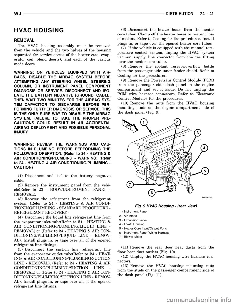
(10) Remove the nuts from the HVAC housing
mounting studs on the engine compartment side of
the dash panel (Fig. 9).
(11) Remove the rear floor heat ducts from the
floor heat duct outlets (Fig. 10).
(12) Unplug the HVAC housing wire harness con-
nectors.
(13) Remove the HVAC housing mounting nuts
from the studs on the passenger compartment side of
the dash panel (Fig. 11).
Fig. 9 HVAC Housing - (rear view)
1 - Instrument Panel
2 - Air Intake
3 - Expansion Valve
4 - HVAC Housing
5 - Heater Core Input/Output Ports
6 - Instrument Panel Wiring Harness
7 - Blower Motor
WJDISTRIBUTION 24 - 41