2003 JEEP GRAND CHEROKEE Park lamps
[x] Cancel search: Park lampsPage 642 of 2199

stalk is moved to the rear Wash position, the Wash
position circuitry within the switch directs battery
current to the rear washer pump/motor unit, and to
both the rear wiper motor control and rear washer
switch output signal inputs of the rear wiper module
electronic circuitry, which causes the wiper motor to
run at a fixed cycle for as long as the Wash mode is
selected plus about three additional fixed wipe cycles.
The rear wiper module electronic circuitry controls
the switching of battery current to the rear wiper
motor brush, which controls wiper motor operation.
The intermittent wipe and wipe-after-wash features
of the rear wiper and washer system are both pro-
vided by the rear wiper module electronic circuitry.
The rear wiper module electronic circuitry also mon-
itors the liftgate flip-up glass ajar switch and will
park the rear wiper blade off of the glass any time it
senses that the liftgate flip-up glass is ajar, the igni-
tion switch is turned to the Off position, or the right
multi-function switch control sleeve is moved to the
Off position. This feature ensures that the rear wiper
blade will not interfere with or be damaged by the
operation of the liftgate flip-up glass. However, if the
ignition switch is turned to the Off position or the
liftgate flip-up glass is opened while the rear wiper is
operating, the right multi-function switch control
sleeve must be cycled to the Off position and back to
the On or Delay position after the ignition switch is
turned back On or the liftgate flip-up glass is closed
before the rear wiper will operate again.
Refer to the owner's manual in the vehicle glove
box for more information on the features and opera-
tion of the rear wiper and washer system.
DIAGNOSIS AND TESTING - REAR WIPER &
WASHER SYSTEM
WIPER SYSTEM
The diagnosis found here addresses an electrically
inoperative rear wiper system. If the rear wiper
motor operates, but the wiper does not move on the
liftgate glass, replace the faulty rear wiper module. If
the wiper operates, but chatters, lifts, or does not
clear the glass, clean and inspect the wiper system
components as required. (Refer to 8 - ELECTRICAL/
REAR WIPERS/WASHERS - INSPECTION) and
(Refer to 8 - ELECTRICAL/REAR WIPERS/WASH-
ERS - CLEANING). Refer to the appropriate wiring
information. The wiring information includes wiring
diagrams, proper wire and connector repair proce-
dures, details of wire harness routing and retention,
connector pin-out information and location views for
the various wire harness connectors, splices and
grounds.WARNING: ON VEHICLES EQUIPPED WITH AIR-
BAGS, DISABLE THE AIRBAG SYSTEM BEFORE
ATTEMPTING ANY STEERING WHEEL, STEERING
COLUMN, OR INSTRUMENT PANEL COMPONENT
DIAGNOSIS OR SERVICE. DISCONNECT AND ISO-
LATE THE BATTERY NEGATIVE (GROUND) CABLE,
THEN WAIT TWO MINUTES FOR THE AIRBAG SYS-
TEM CAPACITOR TO DISCHARGE BEFORE PER-
FORMING FURTHER DIAGNOSIS OR SERVICE. THIS
IS THE ONLY SURE WAY TO DISABLE THE AIRBAG
SYSTEM. FAILURE TO TAKE THE PROPER PRE-
CAUTIONS COULD RESULT IN ACCIDENTAL AIR-
BAG DEPLOYMENT AND POSSIBLE PERSONAL
INJURY.
(1) Check that the interior lighting switch on the
control stalk of the left multi-function switch is not
in the dome lamp disable position. With all four
doors and the liftgate closed, open the liftgate flip-up
glass. The interior lamps should light. If not, depress
the cargo lamp lens to actuate the cargo lamp defeat
switch and the interior lamps should light. Close all
four doors, the liftgate and the liftgate flip-up glass.
Note whether the interior lamps remain lighted.
They should turn off after about thirty seconds. If
OK, go to Step 2. If not OK, go to Step 9.
(2) Check the fused B(+) fuse (Fuse8-15ampere)
in the Junction Block (JB). If OK, go to Step 3. If not
OK, repair the shorted circuit or component as
required and replace the faulty fuse.
(3) Check for battery voltage at the fused B(+) fuse
(Fuse8-15ampere) in the JB. If OK, go to Step 4. If
not OK, repair the open fused B(+) circuit between
the JB and the Power Distribution Center (PDC) as
required.
(4) Check the fused ignition switch output (run-
acc) fuse (Fuse 29 - 10 ampere) in the JB. If OK, go
to Step 5. If not OK, repair the shorted circuit or
component as required and replace the faulty fuse.
(5) Turn the ignition switch to the On position.
Check for battery voltage at the fused ignition switch
output (run-acc) fuse (Fuse 29 - 10 ampere) in the
JB. If OK, turn the ignition switch to the Off position
and go to Step 6. If not OK, repair the open fused
ignition switch output (run-acc) circuit between the
JB and the ignition switch as required.
(6) Disconnect and isolate the battery negative
cable. Disconnect the instrument panel wire harness
connector for the right multi-function switch from the
switch connector receptacle. Reconnect the battery
negative cable. Turn the ignition switch to the On
position. Check for battery voltage at the fused igni-
tion switch output (run-acc) circuit cavity of the
instrument panel wire harness connector for the
right multi-function switch. If OK, go to Step 7. If
not OK, repair the open fused ignition switch output
WJREAR WIPERS/WASHERS 8R - 35
REAR WIPERS/WASHERS (Continued)
Page 672 of 2199

8W-02 COMPONENT INDEX
Component Page
A/C Compressor Clutch................. 8W-42
A/C Pressure Transducer................ 8W-42
Accelerator Pedal Position Sensor......... 8W-30
Accessory Delay Relay.................. 8W-64
Adjustable Pedals..................... 8W-30
Airbags............................. 8W-43
Ambient Temperature Sensor............ 8W-45
Antennas............................ 8W-47
Ash Receiver Lamp.................... 8W-44
Auto Shut Down Relay................. 8W-30
Automatic Day/Night Mirror............. 8W-49
Automatic Headlamp Light Sensor/VTSS
LED.............................. 8W-39
Automatic Zone Control Module.......... 8W-42
Back-Up Lamp Relay................... 8W-51
Battery Temperature Sensor............. 8W-30
Battery............................. 8W-20
Blend Door Motor/Actuator.............. 8W-42
Blower Motor......................... 8W-42
Body Control Module................... 8W-45
Boost Pressure Sensor.................. 8W-30
Brake Lamp Switch.................... 8W-33
Camshaft Position Sensor............... 8W-30
Capacitors........................... 8W-30
Cargo Lamp.......................... 8W-44
Center High Mounted Stop Lamp......... 8W-51
Cigar Lighter......................... 8W-41
Circuit Breakers...................... 8W-12
Clockspring.................. 8W-33, 41, 43, 47
Coil On Plugs......................... 8W-30
Coil Rail............................. 8W-30
Combination Flasher................... 8W-52
Compact Disc Changer.................. 8W-47
Controller Antilock Brake............... 8W-35
Coolant Level Sensor................... 8W-45
Courtesy Lamps....................... 8W-44
Crankcase Heater..................... 8W-30
Crankshaft Position Sensor.............. 8W-30
Cylinder Lock Switches................. 8W-61
Data Link Connector................... 8W-18
Diagnostic Junction Port................ 8W-18
EGR Solenoid......................... 8W-30
Electric Brake........................ 8W-54
Electronic Speed Control Servo........... 8W-33
Engine Control Module................. 8W-30
Engine Coolant Temperature Sensor...... 8W-30
Engine Oil Pressure Sensor.............. 8W-30
Engine Starter Motor................... 8W-21
EVAP/Purge Solenoid................... 8W-30
Fog Lamps........................ 8W-50, 51
Fuel Injectors......................... 8W-30
Fuel Pressure Sensor................... 8W-30Component Page
Fuel Pressure Solenoid................. 8W-30
Fuel Pump........................... 8W-30
Fuel Tank Module..................... 8W-30
Fuses............................ 8W-10, 12
Fusible Link....................... 8W-10, 20
Grounds............................. 8W-15
Generator......................... 8W-20, 30
Glove Box Lamp...................... 8W-44
Glow Plugs........................... 8W-30
Headlamp Leveling Motor............... 8W-50
Heated Seats......................... 8W-63
High Beam Headlamps................. 8W-50
Hood Ajar Switch...................... 8W-39
Horns............................... 8W-41
Hydraulic Cooling Module............ 8W-30, 42
Idle Air Control Motor.................. 8W-30
Ignition Switch....................... 8W-10
Impact Sensors....................... 8W-43
Input Speed Sensor.................... 8W-31
Instrument Cluster.................... 8W-40
Intake Air Temperature Sensor........... 8W-30
Intake Port Swirl Actuator.............. 8W-30
Intrusion Transceiver Module............ 8W-49
Junction Block........................ 8W-12
Knock Sensor......................... 8W-30
Lamp Assemblies................... 8W-51, 52
Leak Detection Pump.................. 8W-30
License Lamps........................ 8W-51
Liftgate............................. 8W-61
Line Pressure Sensor................... 8W-31
Low Beam Headlamps.................. 8W-50
Low Beam Relay...................... 8W-50
Low Beam/Daytime Running Lamp Relay . . . 8W-50
Lumbar Motor........................ 8W-63
Lumbar Switch....................... 8W-63
Manifold Absolute Pressure Sensor........ 8W-30
Manual Temperature Control............. 8W-42
Mass Air Flow Sensor.................. 8W-30
Memory Set Switch................. 8W-62, 63
Mode Door Motor/Actuator............... 8W-42
Multi-Function Switch............... 8W-50, 53
Output Speed Sensor................... 8W-31
Overhead Map/Courtesy Lamp........... 8W-44
Oxygen Sensors....................... 8W-30
Park Brake Switch..................... 8W-40
Park Lamp........................... 8W-50
Park/Neutral Position Switch............ 8W-31
Park/Turn Signal Lamps................ 8W-50
Power Amplifier....................... 8W-47
Power Connector...................... 8W-41
Power Distribution Center............... 8W-10
Power Mirrors........................ 8W-62
WJ8W-02 COMPONENT INDEX 8W - 02 - 1
Page 1142 of 2199

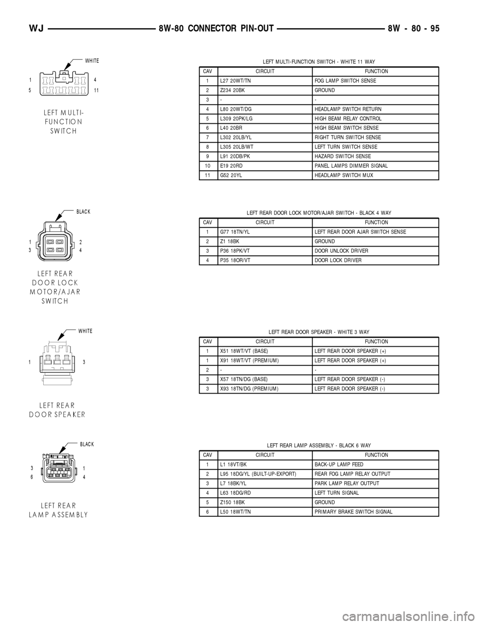
LEFT MULTI-FUNCTION SWITCH - WHITE 11 WAY
CAV CIRCUIT FUNCTION
1 L27 20WT/TN FOG LAMP SWITCH SENSE
2 Z234 20BK GROUND
3- -
4 L80 20WT/DG HEADLAMP SWITCH RETURN
5 L309 20PK/LG HIGH BEAM RELAY CONTROL
6 L40 20BR HIGH BEAM SWITCH SENSE
7 L302 20LB/YL RIGHT TURN SWITCH SENSE
8 L305 20LB/WT LEFT TURN SWITCH SENSE
9 L91 20DB/PK HAZARD SWITCH SENSE
10 E19 20RD PANEL LAMPS DIMMER SIGNAL
11 G52 20YL HEADLAMP SWITCH MUX
LEFT REAR DOOR LOCK MOTOR/AJAR SWITCH - BLACK 4 WAY
CAV CIRCUIT FUNCTION
1 G77 18TN/YL LEFT REAR DOOR AJAR SWITCH SENSE
2 Z1 18BK GROUND
3 P36 18PK/VT DOOR UNLOCK DRIVER
4 P35 18OR/VT DOOR LOCK DRIVER
LEFT REAR DOOR SPEAKER - WHITE 3 WAY
CAV CIRCUIT FUNCTION
1 X51 18WT/VT (BASE) LEFT REAR DOOR SPEAKER (+)
1 X91 18WT/VT (PREMIUM) LEFT REAR DOOR SPEAKER (+)
2- -
3 X57 18TN/DG (BASE) LEFT REAR DOOR SPEAKER (-)
3 X93 18TN/DG (PREMIUM) LEFT REAR DOOR SPEAKER (-)
LEFT REAR LAMP ASSEMBLY - BLACK 6 WAY
CAV CIRCUIT FUNCTION
1 L1 18VT/BK BACK-UP LAMP FEED
2 L95 18DG/YL (BUILT-UP-EXPORT) REAR FOG LAMP RELAY OUTPUT
3 L7 18BK/YL PARK LAMP RELAY OUTPUT
4 L63 18DG/RD LEFT TURN SIGNAL
5 Z150 18BK GROUND
6 L50 18WT/TN PRIMARY BRAKE SWITCH SIGNAL
WJ8W-80 CONNECTOR PIN-OUT 8W - 80 - 95
Page 1167 of 2199

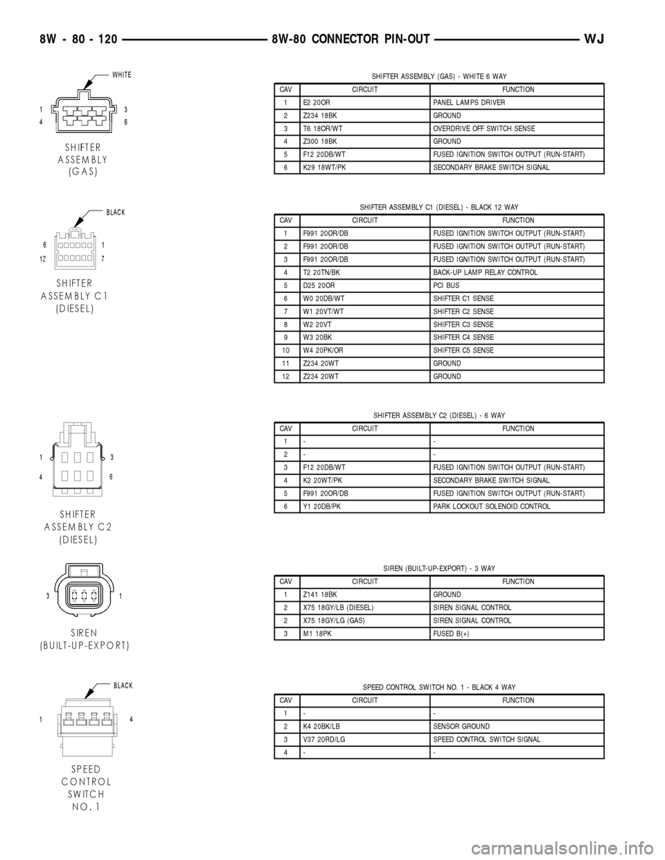
SHIFTER ASSEMBLY (GAS) - WHITE 6 WAY
CAV CIRCUIT FUNCTION
1 E2 20OR PANEL LAMPS DRIVER
2 Z234 18BK GROUND
3 T6 18OR/WT OVERDRIVE OFF SWITCH SENSE
4 Z300 18BK GROUND
5 F12 20DB/WT FUSED IGNITION SWITCH OUTPUT (RUN-START)
6 K29 18WT/PK SECONDARY BRAKE SWITCH SIGNAL
SHIFTER ASSEMBLY C1 (DIESEL) - BLACK 12 WAY
CAV CIRCUIT FUNCTION
1 F991 20OR/DB FUSED IGNITION SWITCH OUTPUT (RUN-START)
2 F991 20OR/DB FUSED IGNITION SWITCH OUTPUT (RUN-START)
3 F991 20OR/DB FUSED IGNITION SWITCH OUTPUT (RUN-START)
4 T2 20TN/BK BACK-UP LAMP RELAY CONTROL
5 D25 20OR PCI BUS
6 W0 20DB/WT SHIFTER C1 SENSE
7 W1 20VT/WT SHIFTER C2 SENSE
8 W2 20VT SHIFTER C3 SENSE
9 W3 20BK SHIFTER C4 SENSE
10 W4 20PK/OR SHIFTER C5 SENSE
11 Z234 20WT GROUND
12 Z234 20WT GROUND
SHIFTER ASSEMBLY C2 (DIESEL)-6WAY
CAV CIRCUIT FUNCTION
1- -
2- -
3 F12 20DB/WT FUSED IGNITION SWITCH OUTPUT (RUN-START)
4 K2 20WT/PK SECONDARY BRAKE SWITCH SIGNAL
5 F991 20OR/DB FUSED IGNITION SWITCH OUTPUT (RUN-START)
6 Y1 20DB/PK PARK LOCKOUT SOLENOID CONTROL
SIREN (BUILT-UP-EXPORT)-3WAY
CAV CIRCUIT FUNCTION
1 Z141 18BK GROUND
2 X75 18GY/LB (DIESEL) SIREN SIGNAL CONTROL
2 X75 18GY/LG (GAS) SIREN SIGNAL CONTROL
3 M1 18PK FUSED B(+)
SPEED CONTROL SWITCH NO. 1 - BLACK 4 WAY
CAV CIRCUIT FUNCTION
1- -
2 K4 20BK/LB SENSOR GROUND
3 V37 20RD/LG SPEED CONTROL SWITCH SIGNAL
4- -
8W - 80 - 120 8W-80 CONNECTOR PIN-OUTWJ
Page 1261 of 2199

DESCRIPTION N´m Ft. In.
Lbs. Lbs.
Transmission Support Bracket
ÐBolt (Manual) 46 34 Ð
Transmission Support Bracket/
CushionÐBolt (4WD Auto) 75 55 Ð
Transmission Support Adaptor
BracketÐBolts (2WD Auto) 75 55 Ð
Exhaust Manifold/PipeÐNuts 27 20 Ð
Intake/Exhaust Manifold
Fasteners #1-5 33 24 Ð
Fasteners #6 and 7 14 Ð 126
Fasteners #8-11 33 24 Ð
Flywheel to Converter
HousingÐBolts38 28 Ð
Flywheel to CrankshaftÐBolts 143 105 Ð
Front Cover to BlockÐBolts
1/4-20 7 Ð 60
5/16-18 22 Ð 192
Fuel RailÐBolts/Stud 12 Ð 108
GeneratorÐBolts 57 42 Ð
Generator Bracket to EngineÐ
Bolts47 35 Ð
Idler Pulley to Cylinder
HeadÐBolt47 35 Ð
Main Bearing CapÐBolts 108 80 Ð
Oil Filter 18 Ð 156
Oil Filter Connector to
Adaptor 47 35 Ð
Block 68 50 Ð
Adaptor Bolts 102 50 Ð
Oil GalleyÐPlug 41 30 Ð
Oil PanÐBolts
1/4-20 9.5 Ð 84
5/16-18 15 Ð 132
Oil PanÐDrain Plug 34 25 Ð
Oil Pump
Mounting Bolts 23 Ð 204
Cover Bolts 8 Ð 70
Rocker Arm Assembly to
Cylinder
HeadÐCapscrews 30 21 Ð
Spark Plugs 37 27 ÐDESCRIPTION N´m Ft. In.
Lbs. Lbs.
Starter MotorÐMounting Bolts 45 33 Ð
Thermostat HousingÐBolts 18 Ð 156
Throttle BodyÐBolts 10 Ð 90
Vibration DamperÐBolt 108 80 Ð
Water Pump to BlockÐBolts 23 17 Ð
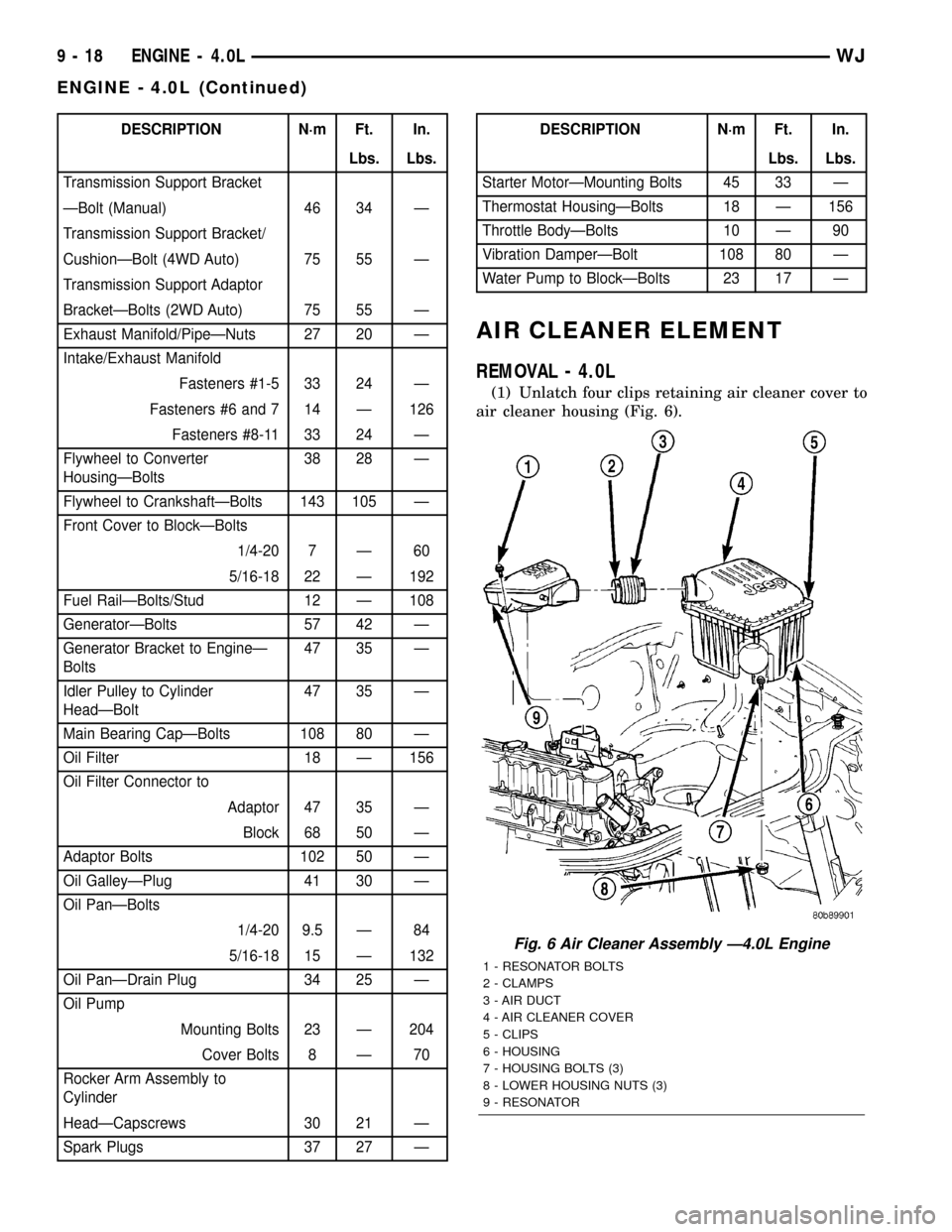
AIR CLEANER ELEMENT
REMOVAL - 4.0L
(1) Unlatch four clips retaining air cleaner cover to
air cleaner housing (Fig. 6).
Fig. 6 Air Cleaner Assembly Ð4.0L Engine
1 - RESONATOR BOLTS
2 - CLAMPS
3 - AIR DUCT
4 - AIR CLEANER COVER
5 - CLIPS
6 - HOUSING
7 - HOUSING BOLTS (3)
8 - LOWER HOUSING NUTS (3)
9 - RESONATOR
9 - 18 ENGINE - 4.0LWJ
ENGINE - 4.0L (Continued)
Page 1789 of 2199

(8) Install the transmission in the vehicle.
(9) Fill the transmission with the recommended
fluid.
TRANSMISSION CONTROL
RELAY
DESCRIPTION
The relay is supplied fused B+ voltage, energized
by the TCM, and is used to supply power to the sole-
noid pack when the transmission is in normal oper-
ating mode.
OPERATION
When the relay is ªoffº, no power is supplied to the
solenoid pack and the transmission is in ªlimp-inº
mode. After a controller reset, the TCM energizes the
relay. Prior to this, the TCM verifies that the con-
tacts are open by checking for no voltage at the
switched battery terminals. After this is verified, the
voltage at the solenoid pack pressure switches is
checked. After the relay is energized, the TCM mon-
itors the terminals to verify that the voltage is
greater than 3 volts.
TRANSMISSION RANGE
SENSOR
DESCRIPTION
The Transmission Range Sensor (TRS) is part of
the solenoid module, which is mounted to the top of
the valve body inside the transmission.
The Transmission Range Sensor (TRS) has five
switch contact pins that:
²Determine shift lever position
²Supply ground to the Starter Relay in Park and
Neutral only.
²Supply +12 V to the backup lamps in Reverse
only.
The TRS also has an integrated temperature sen-
sor (thermistor) that communicates transmission
temperature to the TCM and PCM.
OPERATION
The Transmission Range Sensor (TRS) communi-
cates shift lever position to the TCM as a combina-
tion of open and closed switches. Each shift lever
position has an assigned combination of switch states
(open/closed) that the TCM receives from four sense
circuits. The TCM interprets this information and
determines the appropriate transmission gear posi-
tion and shift schedule.
There are many possible combinations of open and
closed switches (codes). Seven of these possible codes
are related to gear position and five are recognized
as ªbetween gearº codes. This results in many codes
which shouldnever occur. These are called
ªinvalidº codes. An invalid code will result in a DTC,
and the TCM will then determine the shift lever
position based on pressure switch data. This allows
reasonably normal transmission operation with a
TRS failure.
GEAR C5 C4 C3 C2 C1
ParkCL OP OP CL CL
Temp 1CL OP OP CL OP
ReverseOP OP OP CL OP
Temp 2OP OP CL CL OP
Neutral 1OP OP CL CL CL
Neutral 2OP CL CL CL CL
Temp 3OP CL CL CL OP
DriveOP CL CL OP OP
Temp 4OP CL OP OP OP
Manual 2CL CL OP OP OP
Temp 5CL OP OP OP OP
Manual 1CL OP CL OP OP
Fig. 117 Checking Torque Converter Seating-Typical
1 - SCALE
2 - STRAIGHTEDGE
21 - 270 AUTOMATIC TRANSMISSION - 545RFEWJ
TORQUE CONVERTER (Continued)