2003 JEEP GRAND CHEROKEE Fill location
[x] Cancel search: Fill locationPage 1654 of 2199

VALVE BODY
DESCRIPTION
The valve body consists of a cast aluminum valve
body, a separator plate, and transfer plate. The valve
body contains valves and check balls that control
fluid delivery to the torque converter clutch, bands,
and frictional clutches. The valve body contains the
following components (Fig. 255), (Fig. 256), (Fig.
257), and (Fig. 258):
²Regulator valve
²Regulator valve throttle pressure plug
²Line pressure plug and sleeve
²Kickdown valve
²Kickdown limit valve
²1-2 shift valve
²1-2 control valve
²2-3 shift valve²2-3 governor plug
²3-4 shift valve
²3-4 timing valve
²3-4 quick fill valve
²3-4 accumulator
²Throttle valve
²Throttle pressure plug
²Switch valve
²Manual valve
²Converter clutch lock-up valve
²Converter clutch lock-up timing Valve
²Shuttle valve
²Shuttle valve throttle plug
²Boost Valve
²10 check balls
By adjusting the spring pressure acting on the reg-
ulator valve, transmission line pressure can be
adjusted.
Fig. 255 Upper Housing Control Valve Locations
1 - UPPER HOUSING 8 - MANUAL VALVE
2 - REGULATOR VALVE 9 - 1-2 GOVERNOR PLUG
3 - SWITCH VALVE 10 - GOVERNOR PLUG COVER
4 - REGULATOR VALVE SPRING 11 - THROTTLE PLUG
5 - KICKDOWN VALVE 12 - 2-3 GOVERNOR PLUG
6 - KICKDOWN DETENT 13 - SHUTTLE VALVE PRIMARY SPRING
7 - THROTTLE VALVE AND SPRING
WJAUTOMATIC TRANSMISSION - 42RE 21 - 135
Page 1686 of 2199

²pressure adjusting screw and bracket assembly
²throttle lever
²manual lever and shaft seal
²throttle lever shaft seal, washer, and E-clip
²fluid filter and screws
²detent ball and spring
²valve body screws
²governor pressure solenoid
²governor pressure sensor and retaining clip
²park lock rod and E-clip
ASSEMBLY
CAUTION: Do not force valves or plugs into place
during reassembly. If the valve body bores, valves
and plugs are free of distortion or burrs, the valve
body components should all slide into place easily.
In addition, do not overtighten the transfer plate
and valve body screws during reassembly. Over-
tightening can distort the housings resulting in
valve sticking, cross leakage and unsatisfactory
operation. Tighten valve body screws to recom-
mended torque only.
LOWER HOUSING
(1) Lubricate valves, springs, and the housing
valve and plug bores with clean transmission fluid
(Fig. 309).
(2) Install 3-4 timing valve spring and valve in
lower housing.
(3) Install 3-4 quick fill valve in lower housing.
(4) Install 3-4 quick fill valve spring and plug in
housing.
(5) Install timing valve end plate. Tighten end
plate screws to 4 N´m (35 in. lbs.) torque.
3-4 ACCUMULATOR
(1) Lubricate accumulator piston, seals and hous-
ing piston bore with clean transmission fluid (Fig.
310).
(2) Install new seal rings on accumulator piston.
(3) Install piston and spring in housing.
(4) Install end plate on housing.
TRANSFER PLATE
(1) Install rear clutch and rear servo check balls in
transfer plate (Fig. 311).
(2) Install filter screen in upper housing separator
plate (Fig. 312).
(3) Align and position upper housing separator
plate on transfer plate (Fig. 313).
(4) Install brace plate (Fig. 313). Tighten brace
attaching screws to 4 N´m (35 in. lbs.) torque.
(5) Install remaining separator plate attaching
screws. Tighten screws to 4 N´m (35 in. lbs.) torque.
UPPER AND LOWER HOUSING
(1) Position upper housing so internal passages
and check ball seats are facing upward. Then install
check balls in housing (Fig. 314). Eight check balls
are used. The single large check ball is approxi-
mately 8.7 mm (11/32 in.) diameter. The single small
check ball is approximately 4.8 mm (3/16 in.) in
diameter. The remaining 6 check balls are approxi-
mately 6.3 mm (1/4 in.) in diameter.
(2) Position assembled transfer plate and upper
housing separator plate on upper housing (Fig. 315).
Be sure filter screen is seated in proper housing
recess.
Fig. 311 Rear Clutch And Rear Servo Check Ball
Locations
1 - REAR CLUTCH CHECK BALL
2 - REAR SERVO CHECK BALL
3 - TRANSFER PLATE
Fig. 312 Separator Plate Filter Screen Installation
1 - UPPER HOUSING SEPARATOR PLATE
2 - FILTER SCREEN
WJAUTOMATIC TRANSMISSION - 42RE 21 - 167
VALVE BODY (Continued)
Page 1800 of 2199

OPERATION
The input gear is splined to the transmission out-
put shaft. It drives the mainshaft through the plan-
etary gear and range hub. The front output shaft is
operated by a drive chain that connects the shaft to a
drive sprocket on the mainshaft. The drive sprocket
is engaged/disengaged by the mode fork, which oper-
ates the mode sleeve and hub. The sleeve and hub
are not equipped with a synchro mechanism for shift-
ing.
OPERATING RANGES
NV242 operating ranges are 2WD (2-wheel drive),
4x4 part-time, 4x4 full time, and 4 Lo.
The 2WD and 4x4 full time ranges can be used at
any time and on any road surface.
The 4x4 part-time and 4 Lo ranges are for off road
use only. The only time these ranges can be used on
hard surface roads, is when the surface is covered
with snow and ice.
DIAGNOSIS AND TESTING - TRANSFER CASE - NV242
DIAGNOSIS CHART
CONDITION POSSIBLE CAUSE CORRECTION
Transfer case difficult to shift or will
not shift into desired range.1) Transfer case shift linkage
binding.1) Repair or replace linkage as
necessary.
2) Insufficient or incorrect lubricant. 2) Drain and refill transfer case with
the correct type and quantity of
lubricant.
3) Internal transfer case
components binding, worn, or
damaged.3) Repair or replace components as
necessary.
Transfer case noisy in all drive
modes.1) Insufficient or incorrect lubricant. 1) Drain and refill transfer case with
the correct type and quantity of
lubricant.
Lubricant leaking from transfer case
seals or vent.1) Transfer case overfilled. 1) Drain lubricant to the correct
level.
2) Transfer case vent closed or
restricted.2) Clean or replace vent as
necessary.
3) Transfer case seals damaged or
installed incorrectly.3) Replace suspect seal.
Transfer case will not shift through
4X4 part time range (light remains
on)1) Incomplete shift due to drivetrain
torque load.1) Momentarily release the
accelerator pedal to complete the
shift.
2) Incorrect tire pressure. 2) Correct tire pressure as
necessary.
3) Excessive Tire wear. 3) Correct tire condition as
necessary.
4) Excessive vehicle loading. 4) Correct as necessary.
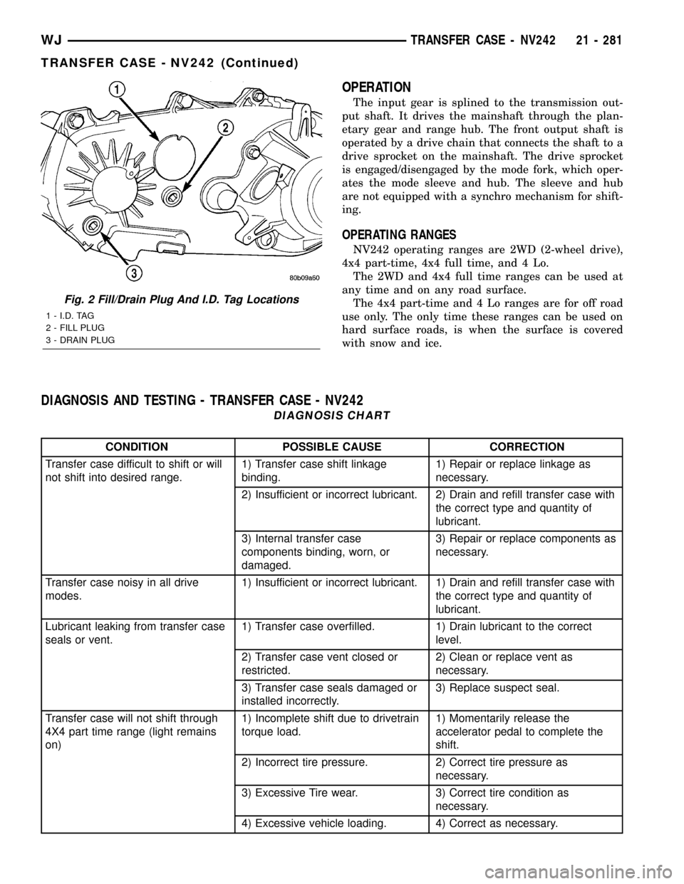
Fig. 2 Fill/Drain Plug And I.D. Tag Locations
1 - I.D. TAG
2 - FILL PLUG
3 - DRAIN PLUG
WJTRANSFER CASE - NV242 21 - 281
TRANSFER CASE - NV242 (Continued)
Page 1829 of 2199

FLUID
STANDARD PROCEDURE - FLUID DRAIN/
REFILL
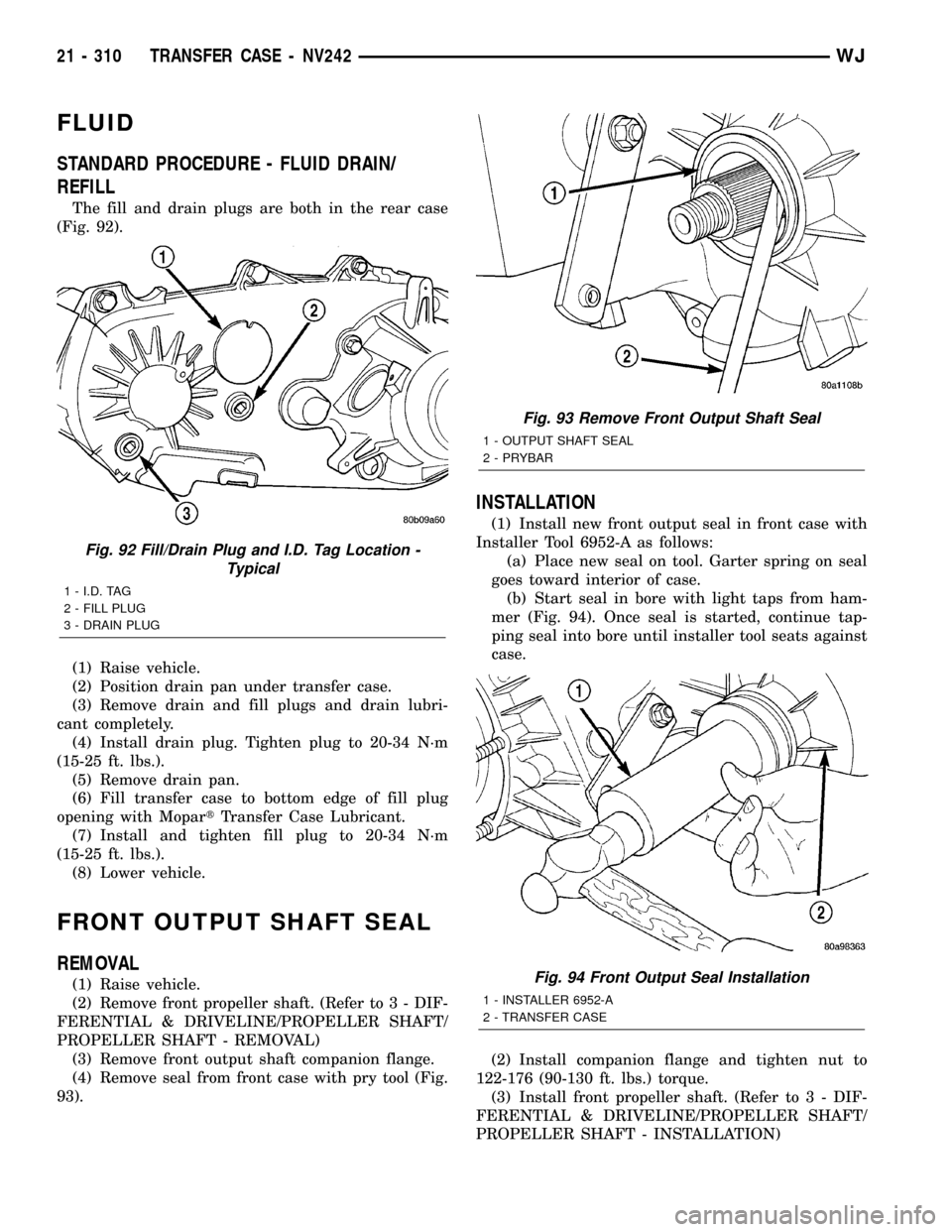
The fill and drain plugs are both in the rear case
(Fig. 92).
(1) Raise vehicle.
(2) Position drain pan under transfer case.
(3) Remove drain and fill plugs and drain lubri-
cant completely.
(4) Install drain plug. Tighten plug to 20-34 N´m
(15-25 ft. lbs.).
(5) Remove drain pan.
(6) Fill transfer case to bottom edge of fill plug
opening with MopartTransfer Case Lubricant.
(7) Install and tighten fill plug to 20-34 N´m
(15-25 ft. lbs.).
(8) Lower vehicle.
FRONT OUTPUT SHAFT SEAL
REMOVAL
(1) Raise vehicle.
(2) Remove front propeller shaft. (Refer to 3 - DIF-
FERENTIAL & DRIVELINE/PROPELLER SHAFT/
PROPELLER SHAFT - REMOVAL)
(3) Remove front output shaft companion flange.
(4) Remove seal from front case with pry tool (Fig.
93).
INSTALLATION
(1) Install new front output seal in front case with
Installer Tool 6952-A as follows:
(a) Place new seal on tool. Garter spring on seal
goes toward interior of case.
(b) Start seal in bore with light taps from ham-
mer (Fig. 94). Once seal is started, continue tap-
ping seal into bore until installer tool seats against
case.
(2) Install companion flange and tighten nut to
122-176 (90-130 ft. lbs.) torque.
(3) Install front propeller shaft. (Refer to 3 - DIF-
FERENTIAL & DRIVELINE/PROPELLER SHAFT/
PROPELLER SHAFT - INSTALLATION)
Fig. 92 Fill/Drain Plug and I.D. Tag Location -
Typical
1 - I.D. TAG
2 - FILL PLUG
3 - DRAIN PLUG
Fig. 93 Remove Front Output Shaft Seal
1 - OUTPUT SHAFT SEAL
2 - PRYBAR
Fig. 94 Front Output Seal Installation
1 - INSTALLER 6952-A
2 - TRANSFER CASE
21 - 310 TRANSFER CASE - NV242WJ
Page 1834 of 2199

TRANSFER CASE - NV247
TABLE OF CONTENTS
page page
TRANSFER CASE - NV247
DESCRIPTION........................315
OPERATION..........................316
DIAGNOSIS AND TESTING - TRANSFER
CASE - NV247.......................316
REMOVAL............................317
DISASSEMBLY........................317
CLEANING...........................324
INSPECTION.........................324
ASSEMBLY...........................326
INSTALLATION........................335
SPECIFICATIONS
TRANSFER CASE - NV247.............336
SPECIAL TOOLS
TRANSFER CASE - NV247.............337FLUID
STANDARD PROCEDURE - FLUID DRAIN/
REFILL............................338
FRONT OUTPUT SHAFT SEAL
REMOVAL............................338
INSTALLATION........................338
REAR RETAINER BUSHING AND SEAL
REMOVAL............................339
INSTALLATION........................339
SHIFT CABLE
REMOVAL............................340
INSTALLATION........................340
TRANSFER CASE - NV247
DESCRIPTION
The NV247 (Fig. 1) is an on-demand 4-wheel drive
transfer case with two operating ranges and a neu-
tral position. Operating ranges are 4-high and 4-low.
The 4-low range is used for extra pulling power in
off-road situations.
TRANSFER CASE IDENTIFICATION
A circular I.D. tag is attached to the rear case of
each NV247 transfer case (Fig. 2). The tag indicates
the following information:
²Model number
²Serial number
²Assembly number
²Gear ratio
²Location of manufacture
The transfer case serial number also represents
the date of build.
Fig. 1 NV247 Transfer Case
Fig. 2 Transfer Case I.D. Tag
1 - FILL PLUG
2 - I.D. TAG
3 - DRAIN PLUG
WJTRANSFER CASE - NV247 21 - 315
Page 1857 of 2199

FLUID
STANDARD PROCEDURE - FLUID DRAIN/
REFILL
The fill and drain plugs are both in the rear case
(Fig. 72).
(1) Raise vehicle.
(2) Position drain pan under transfer case.
(3) Remove drain and fill plugs and drain lubri-
cant completely.
(4) Install drain plug. Tighten plug to 20-34 N´m
(15-25 ft. lbs.).
(5) Remove drain pan.(6) Fill transfer case to bottom edge of fill plug
opening with MopartTransfer Case Lubricant.
(7) Install and tighten fill plug to 20-34 N´m
(15-25 ft. lbs.).
(8) Lower vehicle.
FRONT OUTPUT SHAFT SEAL
REMOVAL
(1) Raise vehicle on hoist.
(2) Remove front propeller shaft. (Refer to 3 - DIF-
FERENTIAL & DRIVELINE/PROPELLER SHAFT/
PROPELLER SHAFT - REMOVAL)
(3) Remove front output shaft companion shaft.
(4) Remove seal from front case with pry tool (Fig.
73).
INSTALLATION
(1) Install new front output seal in front case with
Installer Tool 6952-A as follows:
(a) Place new seal on tool. Garter spring on seal
goes toward interior of case.
(b) Start seal in bore with light taps from ham-
mer (Fig. 74). Once seal is started, continue tap-
ping seal into bore until installer tool seats against
case.
(2) Install companion flange and torque nut to
122-176 N´m (90-130 ft. lbs.).
(3) Install front propeller shaft. (Refer to 3 - DIF-
FERENTIAL & DRIVELINE/PROPELLER SHAFT/
PROPELLER SHAFT - INSTALLATION)
Installer, Bearign - 8128
Installer, Seal - 7884
Fig. 72 Fill/Drain Plug and I.D. Tag Location -
Typical
1 - I.D. TAG
2 - FILL PLUG
3 - DRAIN PLUG
Fig. 73 Remove Front Output Shaft Seal
1 - OUTPUT SHAFT SEAL
2 - PRYBAR
21 - 338 TRANSFER CASE - NV247WJ
TRANSFER CASE - NV247 (Continued)
Page 1985 of 2199

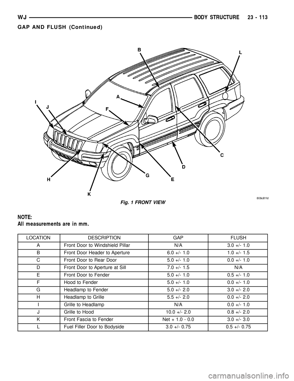
NOTE:
All measurements are in mm.
LOCATION DESCRIPTION GAP FLUSH
A Front Door to Windshield Pillar N/A 3.0 +/- 1.0
B Front Door Header to Aperture 6.0 +/- 1.0 1.0 +/- 1.5
C Front Door to Rear Door 5.0 +/- 1.0 0.0 +/- 1.0
D Front Door to Aperture at Sill 7.0 +/- 1.5 N/A
E Front Door to Fender 5.0 +/- 1.0 0.5 +/- 1.0
F Hood to Fender 5.0 +/- 1.0 0.0 +/- 1.0
G Headlamp to Fender 5.0 +/- 2.0 3.0 +/- 2.0
H Headlamp to Grille 5.5 +/- 2.0 0.0 +/- 2.0
I Grille to Headlamp N/A 0.0 +/- 1.0
J Grille to Hood 10.0 +/- 2.0 0.8 +/- 2.0
K Front Fascia to Fender Net + 1.0 - 0.0 3.0 +/- 3.0
L Fuel Filler Door to Bodyside 3.0 +/- 0.75 0.5 +/- 0.75
Fig. 1 FRONT VIEW
WJBODY STRUCTURE 23 - 113
GAP AND FLUSH (Continued)
Page 1991 of 2199

SEALER LOCATIONS
SPECIFICATIONS
SEALER LOCATIONS
INDEX
DESCRIPTION FIGURE
APPLICATION METHODS 6
COWL PLENUM AND DASH PANEL 7
DASH, COWL AND PLENUM 8
INNER FENDER AND COWL 9
LOWER PLENUM AND BAFFLE 10
A-PILLAR 11
COWL SIDE ATTACHMENT 12
BODYSIDE ATTACHMENT 13
BODYSIDE INNER AND OUTER TO COWL 14
FENDER ATTACHMENT 15
DOOR HINGE BOLT HOLES 16
A-PILLAR AND B-PILLAR HINGE AREA 17
B-PILLAR AND SILL 18
SILL AND B-PILLAR 19
BODYSIDE APERTURE AND REAR WHEELHOUSE 20
FUEL FILLER GUSSET 21
OUTER WHEELHOUSE FLANGE 22
LIFTGATE OPENING 23
INNER WHEELHOUSE FLANGE TO BODYSIDE APERTURE 24
WHEELHOUSE LOWER 25
REAR INNER CROSSMEMBER 26
ROOF TO BODY SIDE APERTURE 27
23 - 118 BODY STRUCTUREWJ