2003 JEEP GRAND CHEROKEE Air Filter
[x] Cancel search: Air FilterPage 1434 of 2199
(8) Connect fuel return and pressure lines to fuel
pump module fittings (Fig. 16). Refer to Quick-Con-
nect Fittings.
(9) Install fuel tank. Refer to Fuel Tank Installa-
tion.
FUEL RAIL
DESCRIPTION
DESCRIPTION - 4.7L
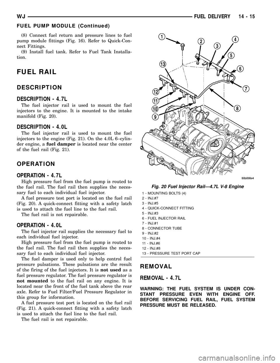
The fuel injector rail is used to mount the fuel
injectors to the engine. It is mounted to the intake
manifold (Fig. 20).
DESCRIPTION - 4.0L
The fuel injector rail is used to mount the fuel
injectors to the engine (Fig. 21). On the 4.0L 6±cylin-
der engine, afuel damperis located near the center
of the fuel rail (Fig. 21).
OPERATION
OPERATION - 4.7L
High pressure fuel from the fuel pump is routed to
the fuel rail. The fuel rail then supplies the neces-
sary fuel to each individual fuel injector.
A fuel pressure test port is located on the fuel rail
(Fig. 20). A quick-connect fitting with a safety latch
is used to attach the fuel line to the fuel rail.
The fuel rail is not repairable.
OPERATION - 4.0L
The fuel injector rail supplies the necessary fuel to
each individual fuel injector.
High pressure fuel from the fuel pump is routed to
the fuel rail. The fuel rail then supplies the neces-
sary fuel to each individual fuel injector.
The fuel damper is used only to help control fuel
pressure pulsations. These pulsations are the result
of the firing of the fuel injectors. It isnot usedas a
fuel pressure regulator. The fuel pressure regulator is
not mountedto the fuel rail on any engine. It is
located near the front of the fuel tank above the rear
axle. Refer to Fuel Filter/Fuel Pressure Regulator in
this group for information.
A fuel pressure test port is located on the fuel rail
(Fig. 21). A quick-connect fitting with a safety latch
is used to attach the fuel line to the fuel rail.
The fuel rail is not repairable.
REMOVAL
REMOVAL - 4.7L
WARNING: THE FUEL SYSTEM IS UNDER CON-
STANT PRESSURE EVEN WITH ENGINE OFF.
BEFORE SERVICING FUEL RAIL, FUEL SYSTEM
PRESSURE MUST BE RELEASED.
Fig. 20 Fuel Injector RailÐ4.7L V-8 Engine
1 - MOUNTING BOLTS (4)
2 - INJ.#7
3 - INJ.#5
4 - QUICK-CONNECT FITTING
5 - INJ.#3
6 - FUEL INJECTOR RAIL
7 - INJ.#1
8 - CONNECTOR TUBE
9 - INJ.#2
10 - INJ.#4
11 - INJ.#6
12 - INJ.#8
13 - PRESSURE TEST PORT CAP
WJFUEL DELIVERY 14 - 15
FUEL PUMP MODULE (Continued)
Page 1438 of 2199

(14) Install air tube (or duct) at top of throttle
body.
(15) Install fuel tank cap.
(16) Connect negative battery cable to battery.
(17) Start engine and check for fuel leaks.
FUEL TANK
DESCRIPTION
The fuel tank is constructed of a plastic material.
Its main functions are for fuel storage and for place-
ment of the fuel pump module and certain ORVR
components.
OPERATION
All models pass a full 360 degree rollover test
without fuel leakage. To accomplish this, fuel and
vapor flow controls are required for all fuel tank con-
nections.
A fuel tank check valve(s) is mounted into the top
of the fuel tank (or pump module). Refer to Fuel
Tank Check Valve for additional information.
An evaporation control system is connected to the
check valve(s) to reduce emissions of fuel vapors into
the atmosphere. When fuel evaporates from the fuel
tank, vapors pass through vent hoses or tubes to a
charcoal canister where they are temporarily held.
When the engine is running, the vapors are drawn
into the intake manifold. Certain models are also
equipped with a self-diagnosing system using a Leak
Detection Pump (LDP). Refer to Emission Control
System for additional information.
Refer to ORVR for On-Board Refueling Vapor
Recovery system information.
REMOVAL
WARNING: THE FUEL SYSTEM IS UNDER CON-
STANT FUEL PRESSURE EVEN WITH ENGINE OFF.
PRESSURE MUST BE RELEASED BEFORE SERVIC-
ING FUEL TANK.
Two different procedures may be used to drain fuel
tank (through ORVR control valve opening at top of
fuel tank, or using DRB scan tool). The quickest is
draining through ORVR control valve opening at top
of fuel tank (Fig. 26).
As an alternative procedure, the electric fuel pump
may be activated allowing tank to be drained at fuel
rail connection. Refer to DRB scan tool for fuel pump
activation procedures. Before disconnecting fuel line
at fuel rail, release fuel pressure. Refer to the Fuel
System Pressure Release Procedure for procedures.
Attach end of Special Adapter Hose Tool number
6539 at fuel rail disconnection. Position opposite end
of 6539 to an approved gasoline draining station.Activate fuel pump with DRB and drain tank until
empty.
If electric fuel pump is not operating, tankMUST
be drained through ORVR control valve opening at
top of fuel tank (Fig. 26).
(1) Release fuel system pressure. Refer to Fuel
System Pressure Release Procedure.
(2) Disconnect negative battery cable at battery.
(3) Raise and support vehicle.
(4) Remove left rear wheel/tire.
CAUTION: HANDLE EVAP, LDP AND ORVR VAPOR /
VACUUM LINES VERY CAREFULLY. THESE LINES
AND HOSES MUST BE FIRMLY CONNECTED.
CHECK THE VAPOR/VACUUM LINES AT THE LDP,
LDP FILTER, EVAP CANISTER, EVAP CANISTER
PURGE SOLENOID AND ORVR COMPONENTS FOR
DAMAGE OR LEAKS. IF A LEAK IS PRESENT, A
DIAGNOSTIC TROUBLE CODE (DTC) MAY BE SET.
(5) Clean top of fuel tank at ORVR control valve
(Fig. 26) or (Fig. 27).
(6) Press release tab in direction of arrow in (Fig.
27) and remove ORVR control valve lock ring
(counter-clockwise). Lift up ORVR control slightly.
Using an approved gasoline draining station, drain
tank until empty through this opening.
(7) Remove stone shield behind left/rear wheel
(Fig. 28). Drill out plastic rivets for removal.
(8) Remove 3 LDP mounting bolts (Fig. 29).
(9) Remove support bracket brace bolt (Fig. 30).
(10) Loosen, but do not remove 2 support bracket
nuts at frame rail (Fig. 29).
(11) To separate and lower front section of two-
piece support bracket, remove 3 attaching bolts on
bottom of support bracket (Fig. 30). While lowering
support bracket, disconnect LDP wiring clip (Fig. 31).
(12) Remove hose clamp (Fig. 32) and remove fuel
fill hose from fuel fill tube.
(13) Cut and discard tie wrap from axle vent hose
(Fig. 32).
(14) Disconnect fuel vent hose from fuel vent tube
(Fig. 32).
(15) Disconnect ORVR hose elbow (Fig. 33) at top
of EVAP canister.
(16) Place hydraulic jack to bottom of fuel tank.
(17) Remove fuel tank-to-rear bumper fascia clips
(Fig. 34).
(18) Remove fuel tank heat shield mounting bolts
(Fig. 35).
CAUTION: To protect fuel tank from exhaust heat,
shield must re-installed after tank installation.
WARNING: PLACE SHOP TOWEL AROUND FUEL
LINES TO CATCH ANY EXCESS FUEL.
WJFUEL DELIVERY 14 - 19
FUEL RAIL (Continued)
Page 1446 of 2199
INLET FILTER
REMOVAL
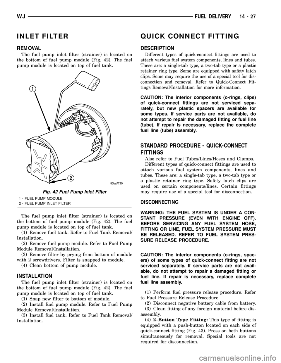
The fuel pump inlet filter (strainer) is located on
the bottom of fuel pump module (Fig. 42). The fuel
pump module is located on top of fuel tank.
The fuel pump inlet filter (strainer) is located on
the bottom of fuel pump module (Fig. 42). The fuel
pump module is located on top of fuel tank.
(1) Remove fuel tank. Refer to Fuel Tank Removal/
Installation.
(2) Remove fuel pump module. Refer to Fuel Pump
Module Removal/Installation.
(3) Remove filter by prying from bottom of module
with 2 screwdrivers. Filter is snapped to module.
(4) Clean bottom of pump module.
INSTALLATION
The fuel pump inlet filter (strainer) is located on
the bottom of fuel pump module (Fig. 42). The fuel
pump module is located on top of fuel tank.
(1) Snap new filter to bottom of module.
(2) Install fuel pump module. Refer to Fuel Pump
Module Removal/Installation.
(3) Install fuel tank. Refer to Fuel Tank Removal/
Installation.
QUICK CONNECT FITTING
DESCRIPTION
Different types of quick-connect fittings are used to
attach various fuel system components, lines and tubes.
These are: a single-tab type, a two-tab type or a plastic
retainer ring type. Some are equipped with safety latch
clips. Some may require the use of a special tool for dis-
connection and removal. Refer to Quick-Connect Fit-
tings Removal/Installation for more information.
CAUTION: The interior components (o-rings, clips)
of quick-connect fittings are not serviced sepa-
rately, but new plastic spacers are available for
some types. If service parts are not available, do
not attempt to repair the damaged fitting or fuel line
(tube). If repair is necessary, replace the complete
fuel line (tube) assembly.
STANDARD PROCEDURE - QUICK-CONNECT
FITTINGS
Also refer to Fuel Tubes/Lines/Hoses and Clamps.
Different types of quick-connect fittings are used to
attach various fuel system components, lines and
tubes. These are: a single-tab type, a two-tab type or
a plastic retainer ring type. Safety latch clips are
used on certain components/lines. Certain fittings
may require use of a special tool for disconnection.
DISCONNECTING
WARNING: THE FUEL SYSTEM IS UNDER A CON-
STANT PRESSURE (EVEN WITH ENGINE OFF).
BEFORE SERVICING ANY FUEL SYSTEM HOSE,
FITTING OR LINE, FUEL SYSTEM PRESSURE MUST
BE RELEASED. REFER TO FUEL SYSTEM PRES-
SURE RELEASE PROCEDURE.
CAUTION: The interior components (o-rings, spac-
ers) of some types of quick-connect fitting are not
serviced separately. If service parts are not avail-
able, do not attempt to repair a damaged fitting or
fuel line. If repair is necessary, replace complete
fuel line assembly.
(1) Perform fuel pressure release procedure. Refer
to Fuel Pressure Release Procedure.
(2) Disconnect negative battery cable from battery.
(3) Clean fitting of any foreign material before dis-
assembly.
(4)2±Button Type Fitting:This type of fitting is
equipped with a push-button located on each side of
quick-connect fitting (Fig. 43). Press on both buttons
simultaneously for removal. Special tools are not
required for disconnection.
Fig. 42 Fuel Pump Inlet Filter
1 - FUEL PUMP MODULE
2 - FUEL PUMP INLET FILTER
WJFUEL DELIVERY 14 - 27
Page 1471 of 2199
THROTTLE BODY
DESCRIPTION
The throttle body is located on the intake manifold.
Fuel does not enter the intake manifold through the
throttle body. Fuel is sprayed into the manifold by
the fuel injectors.
OPERATION
Filtered air from the air cleaner enters the intake
manifold through the throttle body. The throttle body
contains an air control passage controlled by an Idle
Air Control (IAC) motor. The air control passage is
used to supply air for idle conditions. A throttle valve
(plate) is used to supply air for above idle conditions.
Certain sensors are attached to the throttle body.
The accelerator pedal cable, speed control cable and
transmission control cable (when equipped) are con-
nected to the throttle body linkage arm.A (factory adjusted) set screw is used to mechani-
cally limit the position of the throttle body throttle
plate.Never attempt to adjust the engine idle
speed using this screw.All idle speed functions are
controlled by the PCM.
REMOVAL
REMOVAL - 4.0L
A (factory adjusted) set screw is used to mechani-
cally limit the position of the throttle body throttle
plate.Never attempt to adjust the engine idle
speed using this screw.All idle speed functions are
controlled by the Powertrain Control Module (PCM).
(1) Remove air cleaner duct and air resonator box
at throttle body.
(2) Disconnect throttle body electrical connectors
at MAP sensor, IAC motor and TPS (Fig. 35).
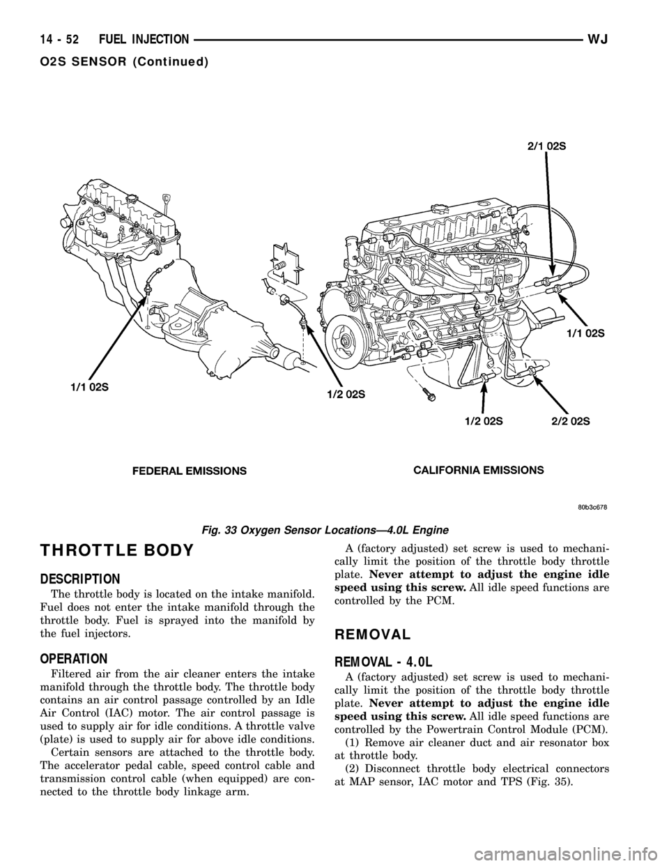
Fig. 33 Oxygen Sensor LocationsÐ4.0L Engine
14 - 52 FUEL INJECTIONWJ
O2S SENSOR (Continued)
Page 1520 of 2199
TRANSMISSION AND TRANSFER CASE
TABLE OF CONTENTS
page page
AUTOMATIC TRANSMISSION - 42RE..........1
AUTOMATIC TRANSMISSION - 545RFE......177TRANSFER CASE - NV242................280
TRANSFER CASE - NV247................315
AUTOMATIC TRANSMISSION - 42RE
TABLE OF CONTENTS
page page
AUTOMATIC TRANSMISSION - 42RE
DESCRIPTION..........................3
OPERATION............................5
DIAGNOSIS AND TESTING
DIAGNOSIS AND TESTING - AUTOMATIC
TRANSMISSION......................11
DIAGNOSIS AND TESTING - PRELIMINARY . 11
DIAGNOSIS AND TESTING - ROAD
TESTING............................11
DIAGNOSIS AND TESTING - HYDRAULIC
PRESSURE TEST.....................12
DIAGNOSIS AND TESTING - AIR CHECKING
TRANSMISSION CLUTCH AND BAND
OPERATION.........................15
DIAGNOSIS AND TESTING - CONVERTER
HOUSING FLUID LEAK.................15
DIAGNOSIS AND TESTING - DIAGNOSIS
CHARTS............................16
STANDARD PROCEDURE - ALUMINUM
THREAD REPAIR......................26
REMOVAL.............................27
DISASSEMBLY.........................29
CLEANING............................34
INSPECTION..........................34
ASSEMBLY............................34
INSTALLATION.........................41
SCHEMATICS AND DIAGRAMS
HYDRAULIC SCHEMATICS..............43
SPECIFICATIONS
TRANSMISSION......................55
SPECIAL TOOLS
RE TRANSMISSIONS..................57
ACCUMULATOR
DESCRIPTION.........................60
OPERATION...........................60
INSPECTION..........................60BANDS
DESCRIPTION.........................61
OPERATION...........................61
ADJUSTMENTS
ADJUSTMENT - BANDS................62
BRAKE TRANSMISSION SHIFT INTERLOCK
MECHANISM
DESCRIPTION.........................63
OPERATION...........................63
DIAGNOSIS AND TESTING - BRAKE
TRANSMISSION SHIFT INTERLOCK.......63
ADJUSTMENTS - BRAKE TRANSMISSION
SHIFT INTERLOCK....................64
ELECTRONIC GOVERNOR
DESCRIPTION.........................65
OPERATION...........................65
REMOVAL.............................67
INSTALLATION.........................67
EXTENSION HOUSING BUSHING
REMOVAL.............................68
INSTALLATION.........................68
EXTENSION HOUSING SEAL
REMOVAL.............................69
INSTALLATION.........................69
FLUID AND FILTER
DIAGNOSIS AND TESTING
DIAGNOSIS AND TESTING - EFFECTS OF
INCORRECT FLUID LEVEL..............69
DIAGNOSIS AND TESTING - CAUSES OF
BURNT FLUID........................69
DIAGNOSIS AND TESTING - FLUID
CONTAMINATION.....................70
STANDARD PROCEDURE
STANDARD PROCEDURE - FLUID LEVEL
CHECK.............................70
WJTRANSMISSION AND TRANSFER CASE 21 - 1
Page 1534 of 2199
TEST CONDITION INDICATION
Governor pressure low at
all mph figuresFaulty governor pressure
solenoid, transmission
control module, or
governor pressure
sensor
Lubrication pressure low
at all throttle positionsClogged fluid cooler or
lines, seal rings leaking,
worn pump bushings,
pump, clutch retainer, or
clogged filter.
Line pressure high Output shaft plugged,
sticky regulator valve
Line pressure low Sticky regulator valve,
clogged filter, worn pump
DIAGNOSIS AND TESTING - AIR CHECKING
TRANSMISSION CLUTCH AND BAND
OPERATION
Air-pressure testing can be used to check transmis-
sion front/rear clutch and band operation. The test
can be conducted with the transmission either in the
vehicle or on the work bench, as a final check, after
overhaul.
Air-pressure testing requires that the oil pan and
valve body be removed from the transmission. The
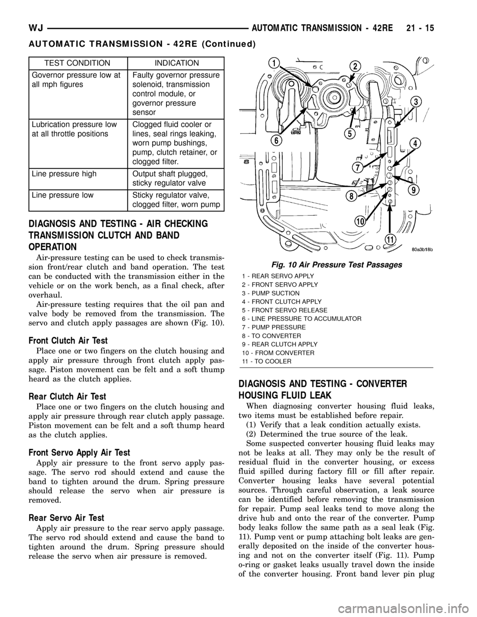
servo and clutch apply passages are shown (Fig. 10).
Front Clutch Air Test
Place one or two fingers on the clutch housing and
apply air pressure through front clutch apply pas-
sage. Piston movement can be felt and a soft thump
heard as the clutch applies.
Rear Clutch Air Test
Place one or two fingers on the clutch housing and
apply air pressure through rear clutch apply passage.
Piston movement can be felt and a soft thump heard
as the clutch applies.
Front Servo Apply Air Test
Apply air pressure to the front servo apply pas-
sage. The servo rod should extend and cause the
band to tighten around the drum. Spring pressure
should release the servo when air pressure is
removed.
Rear Servo Air Test
Apply air pressure to the rear servo apply passage.
The servo rod should extend and cause the band to
tighten around the drum. Spring pressure should
release the servo when air pressure is removed.
DIAGNOSIS AND TESTING - CONVERTER
HOUSING FLUID LEAK
When diagnosing converter housing fluid leaks,
two items must be established before repair.
(1) Verify that a leak condition actually exists.
(2) Determined the true source of the leak.
Some suspected converter housing fluid leaks may
not be leaks at all. They may only be the result of
residual fluid in the converter housing, or excess
fluid spilled during factory fill or fill after repair.
Converter housing leaks have several potential
sources. Through careful observation, a leak source
can be identified before removing the transmission
for repair. Pump seal leaks tend to move along the
drive hub and onto the rear of the converter. Pump
body leaks follow the same path as a seal leak (Fig.
11). Pump vent or pump attaching bolt leaks are gen-
erally deposited on the inside of the converter hous-
ing and not on the converter itself (Fig. 11). Pump
o-ring or gasket leaks usually travel down the inside
of the converter housing. Front band lever pin plug
Fig. 10 Air Pressure Test Passages
1 - REAR SERVO APPLY
2 - FRONT SERVO APPLY
3 - PUMP SUCTION
4 - FRONT CLUTCH APPLY
5 - FRONT SERVO RELEASE
6 - LINE PRESSURE TO ACCUMULATOR
7 - PUMP PRESSURE
8 - TO CONVERTER
9 - REAR CLUTCH APPLY
10 - FROM CONVERTER
11 - TO COOLER
WJAUTOMATIC TRANSMISSION - 42RE 21 - 15
AUTOMATIC TRANSMISSION - 42RE (Continued)
Page 1536 of 2199
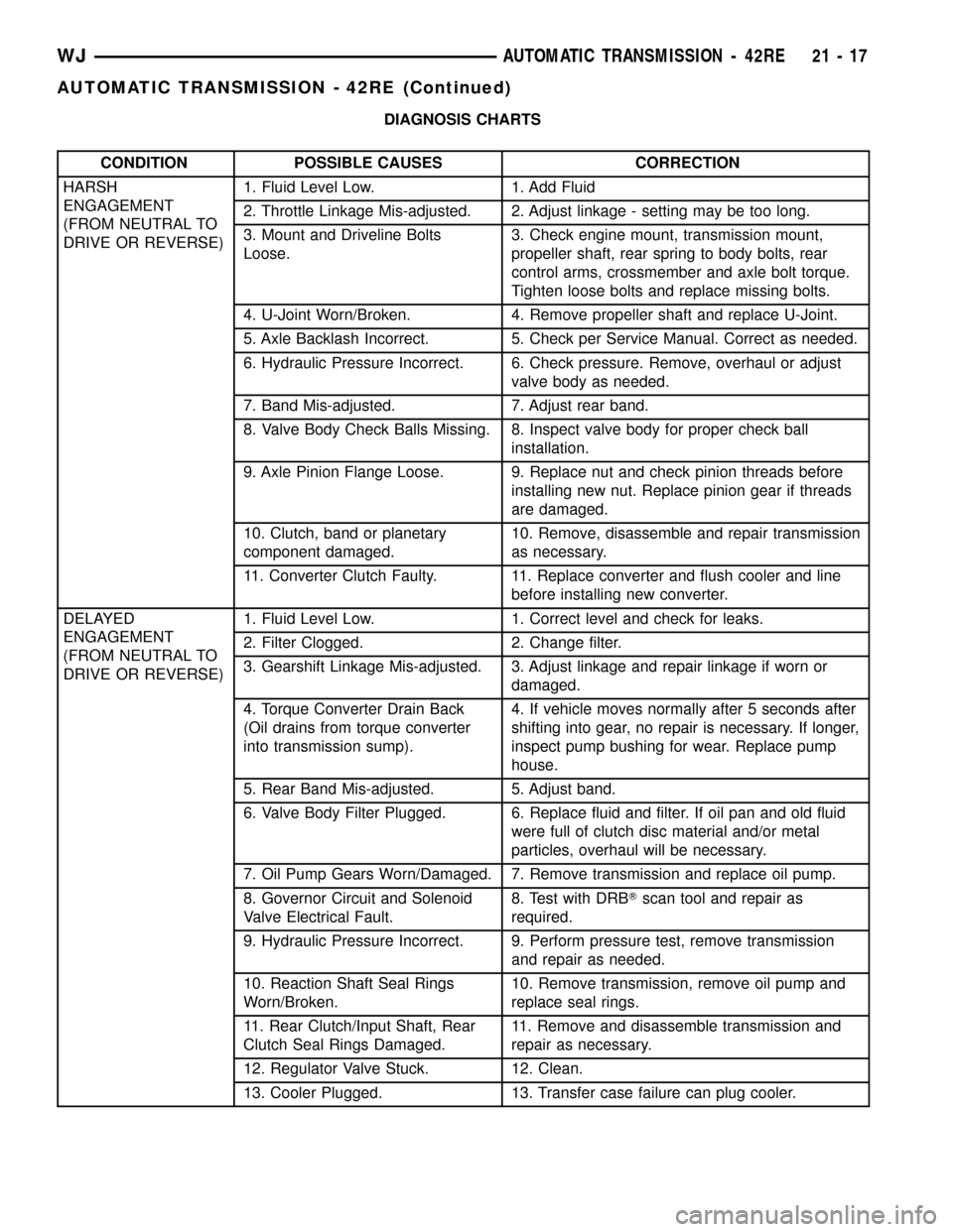
DIAGNOSIS CHARTS
CONDITION POSSIBLE CAUSES CORRECTION
HARSH
ENGAGEMENT
(FROM NEUTRAL TO
DRIVE OR REVERSE)1. Fluid Level Low. 1. Add Fluid
2. Throttle Linkage Mis-adjusted. 2. Adjust linkage - setting may be too long.
3. Mount and Driveline Bolts
Loose.3. Check engine mount, transmission mount,
propeller shaft, rear spring to body bolts, rear
control arms, crossmember and axle bolt torque.
Tighten loose bolts and replace missing bolts.
4. U-Joint Worn/Broken. 4. Remove propeller shaft and replace U-Joint.
5. Axle Backlash Incorrect. 5. Check per Service Manual. Correct as needed.
6. Hydraulic Pressure Incorrect. 6. Check pressure. Remove, overhaul or adjust
valve body as needed.
7. Band Mis-adjusted. 7. Adjust rear band.
8. Valve Body Check Balls Missing. 8. Inspect valve body for proper check ball
installation.
9. Axle Pinion Flange Loose. 9. Replace nut and check pinion threads before
installing new nut. Replace pinion gear if threads
are damaged.
10. Clutch, band or planetary
component damaged.10. Remove, disassemble and repair transmission
as necessary.
11. Converter Clutch Faulty. 11. Replace converter and flush cooler and line
before installing new converter.
DELAYED
ENGAGEMENT
(FROM NEUTRAL TO
DRIVE OR REVERSE)1. Fluid Level Low. 1. Correct level and check for leaks.
2. Filter Clogged. 2. Change filter.
3. Gearshift Linkage Mis-adjusted. 3. Adjust linkage and repair linkage if worn or
damaged.
4. Torque Converter Drain Back
(Oil drains from torque converter
into transmission sump).4. If vehicle moves normally after 5 seconds after
shifting into gear, no repair is necessary. If longer,
inspect pump bushing for wear. Replace pump
house.
5. Rear Band Mis-adjusted. 5. Adjust band.
6. Valve Body Filter Plugged. 6. Replace fluid and filter. If oil pan and old fluid
were full of clutch disc material and/or metal
particles, overhaul will be necessary.
7. Oil Pump Gears Worn/Damaged. 7. Remove transmission and replace oil pump.
8. Governor Circuit and Solenoid
Valve Electrical Fault.8. Test with DRBTscan tool and repair as
required.
9. Hydraulic Pressure Incorrect. 9. Perform pressure test, remove transmission
and repair as needed.
10. Reaction Shaft Seal Rings
Worn/Broken.10. Remove transmission, remove oil pump and
replace seal rings.
11. Rear Clutch/Input Shaft, Rear
Clutch Seal Rings Damaged.11. Remove and disassemble transmission and
repair as necessary.
12. Regulator Valve Stuck. 12. Clean.
13. Cooler Plugged. 13. Transfer case failure can plug cooler.
WJAUTOMATIC TRANSMISSION - 42RE 21 - 17
AUTOMATIC TRANSMISSION - 42RE (Continued)
Page 1537 of 2199
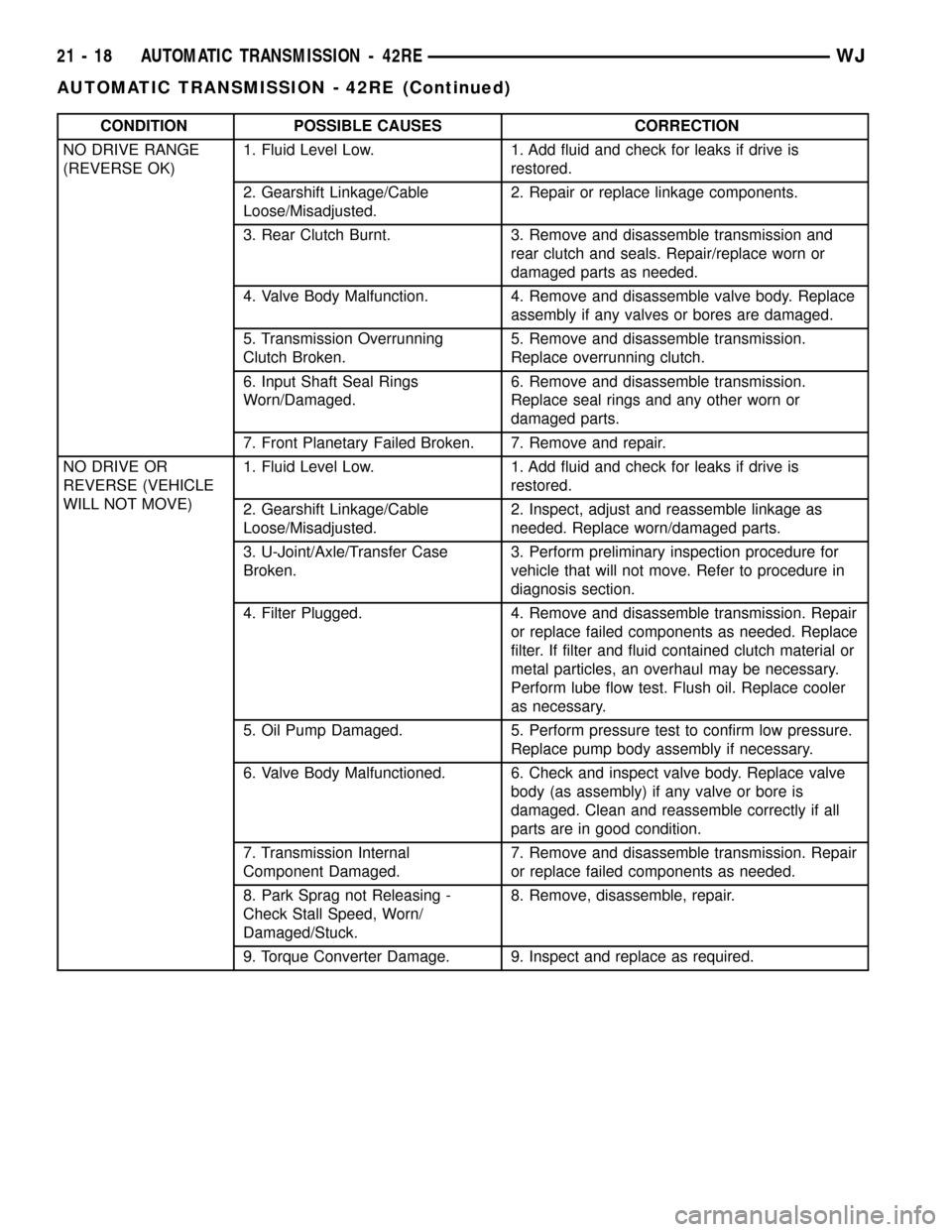
CONDITION POSSIBLE CAUSES CORRECTION
NO DRIVE RANGE
(REVERSE OK)1. Fluid Level Low. 1. Add fluid and check for leaks if drive is
restored.
2. Gearshift Linkage/Cable
Loose/Misadjusted.2. Repair or replace linkage components.
3. Rear Clutch Burnt. 3. Remove and disassemble transmission and
rear clutch and seals. Repair/replace worn or
damaged parts as needed.
4. Valve Body Malfunction. 4. Remove and disassemble valve body. Replace
assembly if any valves or bores are damaged.
5. Transmission Overrunning
Clutch Broken.5. Remove and disassemble transmission.
Replace overrunning clutch.
6. Input Shaft Seal Rings
Worn/Damaged.6. Remove and disassemble transmission.
Replace seal rings and any other worn or
damaged parts.
7. Front Planetary Failed Broken. 7. Remove and repair.
NO DRIVE OR
REVERSE (VEHICLE
WILL NOT MOVE)1. Fluid Level Low. 1. Add fluid and check for leaks if drive is
restored.
2. Gearshift Linkage/Cable
Loose/Misadjusted.2. Inspect, adjust and reassemble linkage as
needed. Replace worn/damaged parts.
3. U-Joint/Axle/Transfer Case
Broken.3. Perform preliminary inspection procedure for
vehicle that will not move. Refer to procedure in
diagnosis section.
4. Filter Plugged. 4. Remove and disassemble transmission. Repair
or replace failed components as needed. Replace
filter. If filter and fluid contained clutch material or
metal particles, an overhaul may be necessary.
Perform lube flow test. Flush oil. Replace cooler
as necessary.
5. Oil Pump Damaged. 5. Perform pressure test to confirm low pressure.
Replace pump body assembly if necessary.
6. Valve Body Malfunctioned. 6. Check and inspect valve body. Replace valve
body (as assembly) if any valve or bore is
damaged. Clean and reassemble correctly if all
parts are in good condition.
7. Transmission Internal
Component Damaged.7. Remove and disassemble transmission. Repair
or replace failed components as needed.
8. Park Sprag not Releasing -
Check Stall Speed, Worn/
Damaged/Stuck.8. Remove, disassemble, repair.
9. Torque Converter Damage. 9. Inspect and replace as required.
21 - 18 AUTOMATIC TRANSMISSION - 42REWJ
AUTOMATIC TRANSMISSION - 42RE (Continued)