2003 JEEP GRAND CHEROKEE 4.7 radiator
[x] Cancel search: 4.7 radiatorPage 273 of 2199

CAUTION: When installing the serpentine accessory
drive belt, belt must be routed correctly. If not,
engine may overheat due to water pump rotating in
wrong direction.
(6) Refill cooling system (Refer to 7 - COOLING -
STANDARD PROCEDURE).
(7) Connect negative battery cable.
(8) Start and warm the engine. Check for leaks.
WATER PUMP - 4.0L
DESCRIPTION
CAUTION: All 4.0L 6-cylinder engines are equipped
with a reverse (counterclockwise) rotating water
pump and thermal viscous fan drive assembly.
REVERSE is stamped or imprinted on the cover of
the viscous fan drive and inner side of the fan. The
letter R is stamped into the back of the water pump
impeller. Engines from previous model years,
depending upon application, may have been
equipped with a forward (clockwise) rotating water
pump. Installation of the wrong water pump or vis-
cous fan drive will cause engine over heating.
A centrifugal water pump circulates coolant
through the water jackets, passages, intake manifold,
radiator core, cooling system hoses and heater core.
The pump is driven from the engine crankshaft by a
single serpentine drive belt.
The water pump impeller is pressed onto the rear
of a shaft that rotates in bearings pressed into the
housing. The housing has two small holes to allow
seepage to escape. The water pump seals are lubri-
cated by the antifreeze in the coolant mixture. No
additional lubrication is necessary (Fig. 45).
DIAGNOSIS AND TESTINGÐWATER PUMP
LOOSE IMPELLER - 4.0L and 4.7L
NOTE: Due to the design of the 4.0L and 4.7L
engine water pumps, testing the pump for a loose
impeller must be done by verifying coolant flow in
the radiator. To accomplish this refer to the follow-
ing procedure.
DO NOT WASTE reusable coolant. If solution is
clean, drain coolant into a clean container for reuse.
(1) Drain coolant until the first row of cores is vis-
ible in the radiator (Refer to 7 - COOLING - STAN-
DARD PROCEDURE) 4.7L Engine or (Refer to 7 -
COOLING - STANDARD PROCEDURE) 4.0L
Engine.(2) Leaving the radiator cap off, start the engine.
Run engine until thermostat opens.
(3) While looking into the radiator through the
radiator fill neck, raise engine rpm to 2000 RPM.
Observe the flow of coolant from the first row of
cores.
(4) If there is no flow or very little flow visable,
replace the water pump.
INSPECTING FOR INLET RESTRICTIONS
Inadequate heater performance may be caused by
a metal casting restriction in the heater hose inlet.
DO NOT WASTE reusable coolant. If solution is
clean, drain the coolant into a clean container for
reuse.
WARNING: DO NOT LOOSEN THE RADIATOR
DRAINCOCK WITH THE SYSTEM HOT AND UNDER
PRESSURE. SERIOUS BURNS FROM THE COOL-
ANT CAN OCCUR.
(1) Drain sufficient coolant from the radiator to
decrease the level below the heater hose inlet. On
4.7L engines this requires complete draining.
(2) Remove the heater hose.
(3) Inspect the inlet for metal casting flash or
other restrictions.
Fig. 45 Water Pump
1 - HEATER HOSE FITTING BORE
2 - WATER PUMP
3 - WATER PUMP HUB
7 - 50 ENGINEWJ
WATER PUMP - 4.7L (Continued)
Page 274 of 2199

NOTE: On 4.0L engines remove the pump from the
engine before removing restriction to prevent con-
tamination of the coolant with debris. . On 4.7L
engine remove the fitting from the timing chain
cover, If the restriction is in the timing chain cover,
remove the timing chain cover.
REMOVAL
CAUTION: If the water pump is replaced because of
mechanical damage, the fan blades and viscous fan
drive should also be inspected. These components
could have been damaged due to excessive vibra-
tion.
The water pump impeller is pressed on the rear of
the pump shaft and bearing assembly. The water
pump is serviced only as a complete assembly.
NOTE: The water pump can be replaced without
discharging the A/C system.
WARNING: DO NOT REMOVE THE BLOCK DRAIN
PLUG(S) OR LOOSEN RADIATOR DRAINCOCK
WITH THE SYSTEM HOT AND UNDER PRESSURE.
SERIOUS BURNS FROM COOLANT CAN OCCUR.
DO NOT WASTE reusable coolant. If the solution
is clean, drain coolant into a clean container for
reuse.
(1) Disconnect negative battery cable at battery.
(2) Drain the cooling system (Refer to 7 - COOL-
ING - STANDARD PROCEDURE).
(3) The thermal viscous fan drive is attached
(threaded) to the water pump hub shaft. Remove fan/
viscous fan drive assembly from water pump by turn-
ing mounting nut counterclockwise as viewed from
front. Threads on viscous fan drive areRIGHT
HANDDo not attempt to remove fan/viscous fan
drive assembly from vehicle at this time.
(4) If water pump is being replaced, do not unbolt
fan blade assembly from thermal viscous fan drive.
(5) Remove fan shroud-to-radiator nuts (Fig. 46).
Do not attempt to remove fan shroud at this time.
(6) Remove fan shroud and fan blade/viscous fan
drive assembly from vehicle as a complete unit.
(7) After removing fan blade/viscous fan drive
assembly,do notplace thermal viscous fan drive in
horizontal position. If stored horizontally, silicone
fluid in viscous fan drive could drain into its bearing
assembly and contaminate lubricant.
Loosen but do not remove the water pump pulley
mounting bolts.Remove accessory drive belt (Refer to 7 - COOL-
ING/ACCESSORY DRIVE/DRIVE BELTS - REMOV-
AL).
Remove the water pump pulley.
(8) Remove the idler pulley (located over the water
pump).
WARNING: CONSTANT TENSION HOSE CLAMPS
ARE USED ON MOST COOLING SYSTEM HOSES.
WHEN REMOVING OR INSTALLING, USE ONLY
TOOLS DESIGNED FOR SERVICING THIS TYPE OF
CLAMP, SUCH AS SPECIAL CLAMP TOOL (NUMBER
6094) (Fig. 47) SNAP-ON CLAMP TOOL (NUMBER
HPC-20) MAY BE USED FOR LARGER CLAMPS.
ALWAYS WEAR SAFETY GLASSES WHEN SERVIC-
ING CONSTANT TENSION CLAMPS.
CAUTION: A number or letter is stamped into the
tongue of constant tension clamps (Fig. 48). If
replacement is necessary, use only an original
equipment clamp with matching number or letter.
(9) Remove lower radiator hose from water pump.
Remove heater hose from water pump fitting.
(10) Remove the five pump mounting bolts (Fig.
49) and remove pump from vehicle. Discard old gas-
ket. Note that one of the five bolts is longer than the
other bolts.
(11) If pump is to be replaced, the heater hose fit-
ting must be removed. Note position of fitting before
removal.
Fig. 46 Fan Shroud Mounting
1 - SHROUD FASTENERS
2 - DRAIN COCK
3 - RADIATOR FAN SHROUD
4 - SHROUD FASTENERS
WJENGINE 7 - 51
WATER PUMP - 4.0L (Continued)
Page 348 of 2199

(3) Position the battery hold down bracket over the
ledge on the inboard side of the battery case in the
battery tray and support unit. Be certain that the
ledge on the bottom of the hold down bracket is ori-
ented towards the inboard side of the battery case.
Proper hold down bracket orientation may also be
determined by noting the direction of the arrow-like
formations of the molded reinforcing ribs on the top
of the hold down bracket. These arrows should be
pointed towards the battery.
(4) Install and tighten the screw that secures the
battery hold down bracket to the U-nut on the
inboard side of the battery tray and support unit.
Tighten thew screw to 3.4 N´m (30 in. lbs.).(5)
Reconnect the battery negative cable terminal clamp
to the battery negative terminal post. Tighten the terminal
clamp pinch-bolt hex nut to 8.4 N´m (75 in. lbs.).
BATTERY CABLE
DESCRIPTION
Fig. 16 Battery Hold Downs Remove/Install
1 - SCREW
2 - HOLD DOWN BRACKET
3 - BATTERY SUPPORT
4 - ACCUMULATOR
5 - NUT
6 - U-NUT
7 - STUD
8 - RADIATOR SUPPORT BRACKET
9 - U-NUT
10 - SCREW
11 - BATTERY TEMPERATURE SENSOR
12 - BATTERY
Fig. 17 Battery Cables - 4.0L Engine
1 - BATTERY POSITIVE CABLE
2 - BATTERY NEGATIVE CABLE
3 - CLIPS
Fig. 18 Battery Cables - 4.7L Engine
1 - BATTERY POSITIVE CABLE
2 - BATTERY NEGATIVE CABLE
3 - CLIPS
WJBATTERY SYSTEM 8F - 17
BATTERY HOLDDOWN (Continued)
Page 352 of 2199

(5) Install and tighten the nut that secures the
battery positive cable eyelet terminal to the B(+) ter-
minal stud on the starter solenoid. Tighten the nut to
11.3 N´m (100 in. lbs.).
(6) Install and tighten the screw that secures the
battery negative cable ground eyelet terminal to the
right side of the engine block. Tighten the screw to
10.2 N´m (90 in. lbs.) for 4.0L engines, or 13.0 N´m
(115 in. lbs.) for 4.7L engines.
(7) Reconnect the battery wire harness connector
to the generator field terminal connector receptacle
on the back of the generator.
(8) Install the generator output cable eyelet termi-
nal onto the generator output terminal stud.
(9) Install and tighten the nut that secures the
generator output cable eyelet terminal to the genera-
tor output terminal stud. Tighten the nut to 10.7
N´m (95 in. lbs.).
(10) Position the cover for the generator output
terminal stud housing onto the back of the generator
and snap it into place.
(11) On models with the 4.7L engine, install the
battery harness clip onto the stud on the right side of
the intake manifold, then install and tighten the nut
that secures the clip to the stud. Tighten the nut to
11.3 N´m (100 in. lbs.).
(12) Install and tighten the screw that secures the
battery negative cable eyelet terminal to the inner
fender shield near the front of the battery. Tighten
the screw to 28.2 N´m (250 in. lbs.).(13) Reconnect the battery wire harness connector
to the right headlamp and dash wire harness connec-
tor located near the front of the battery.
(14) Install the battery positive cable and genera-
tor output cable eyelet terminal onto the PDC B(+)
terminal studs.
(15) Install and tighten the two nuts that secure
the battery positive cable and generator output cable
eyelet terminal to the PDC B(+) terminal studs.
Tighten the nuts to 11.3 N´m (100 in. lbs.).
(16) Close and latch the PDC cover.
(17) Reconnect the battery positive cable terminal
clamp to the battery positive terminal post. Tighten
the terminal clamp pinch-bolt hex nut to 6.8 N´m (60
in. lbs.).
(18) Reconnect the battery negative cable terminal
clamp to the battery negative terminal post. Tighten
the terminal clamp pinch-bolt hex nut to 6.8 N´m (60
in. lbs.).
(19) Apply a thin coating of petroleum jelly or
chassis grease to the exposed surfaces of the battery
cable terminal clamps and the battery terminal
posts.BATTERY TRAY
DESCRIPTION
The battery is mounted in a molded plastic battery
tray and support unit (Fig. 25) located in the right
front corner of the engine compartment. The battery
tray and support unit is secured at the rear with a
nut to a stud on the front wheelhouse inner panel, at
the outboard side with a screw to the side cowl rein-
forcement panel, and at the front with a screw
through a U-nut on a bracket of the radiator support.
The battery tray and support unit also includes
three upright stanchions that are molded into the
outboard side of the unit. These stanchions support
the Power Distribution Center (PDC). Refer to
Power Distribution Centerin the Power Distribu-
tion section of this service manual for more informa-
tion on the PDC.
A hole in the bottom of the battery tray is fitted
with a battery temperature sensor. Refer toBattery
Temperature Sensorin the Charging section of
this service manual for more information on the bat-
tery temperature sensor. Refer toBattery Hold
Downin this section of the service manual for more
information on the battery hold down hardware.
Fig. 24 Battery Cables - 4.7L Engine
1 - BATTERY POSITIVE CABLE
2 - BATTERY NEGATIVE CABLE
3 - CLIPS
WJBATTERY SYSTEM 8F - 21
BATTERY CABLE (Continued)
Page 1051 of 2199

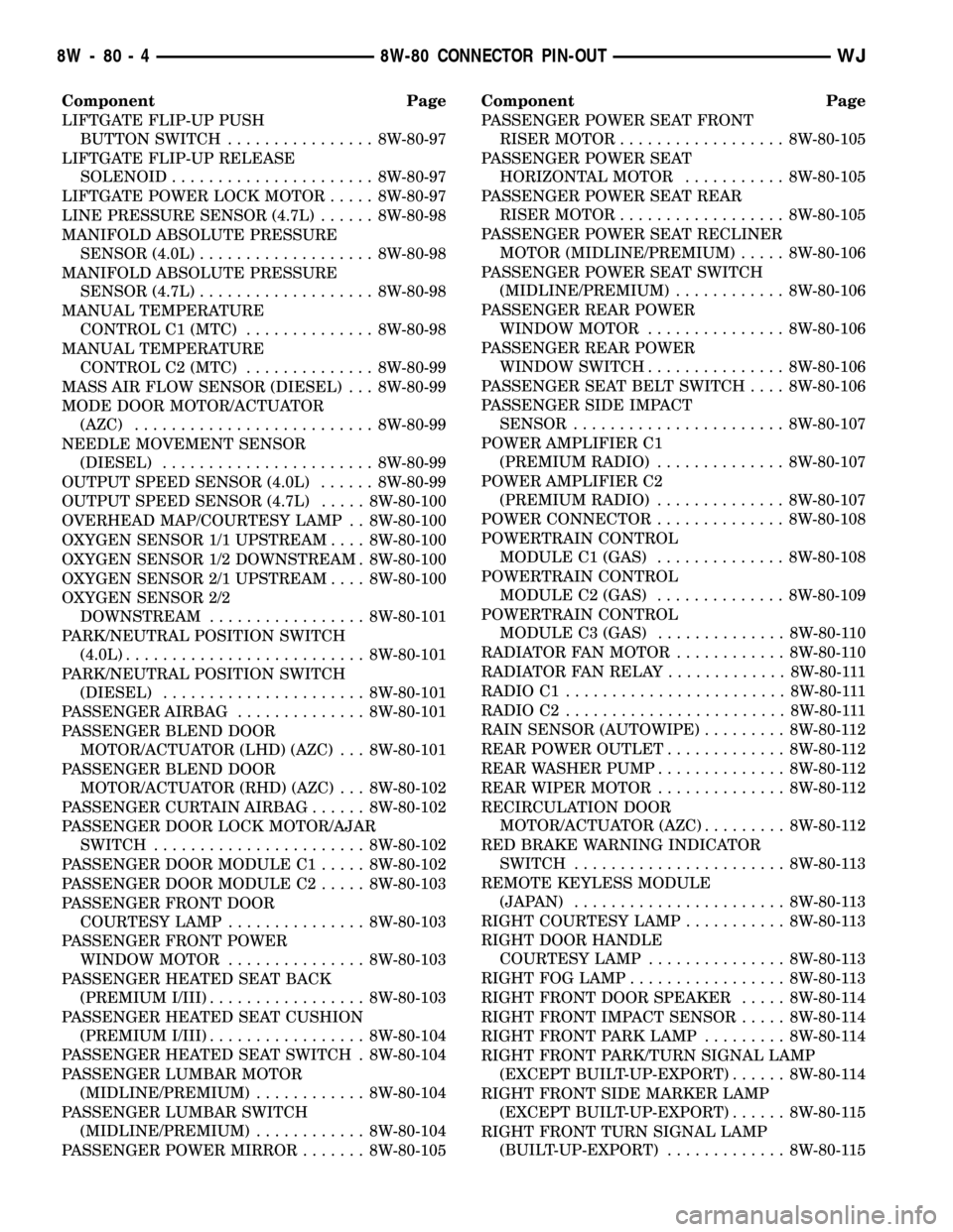
Component Page
LIFTGATE FLIP-UP PUSH
BUTTON SWITCH................ 8W-80-97
LIFTGATE FLIP-UP RELEASE
SOLENOID...................... 8W-80-97
LIFTGATE POWER LOCK MOTOR..... 8W-80-97
LINE PRESSURE SENSOR (4.7L)...... 8W-80-98
MANIFOLD ABSOLUTE PRESSURE
SENSOR (4.0L)................... 8W-80-98
MANIFOLD ABSOLUTE PRESSURE
SENSOR (4.7L)................... 8W-80-98
MANUAL TEMPERATURE
CONTROL C1 (MTC).............. 8W-80-98
MANUAL TEMPERATURE
CONTROL C2 (MTC).............. 8W-80-99
MASS AIR FLOW SENSOR (DIESEL) . . . 8W-80-99
MODE DOOR MOTOR/ACTUATOR
(AZC).......................... 8W-80-99
NEEDLE MOVEMENT SENSOR
(DIESEL)....................... 8W-80-99
OUTPUT SPEED SENSOR (4.0L)...... 8W-80-99
OUTPUT SPEED SENSOR (4.7L)..... 8W-80-100
OVERHEAD MAP/COURTESY LAMP . . 8W-80-100
OXYGEN SENSOR 1/1 UPSTREAM.... 8W-80-100
OXYGEN SENSOR 1/2 DOWNSTREAM . 8W-80-100
OXYGEN SENSOR 2/1 UPSTREAM.... 8W-80-100
OXYGEN SENSOR 2/2
DOWNSTREAM................. 8W-80-101
PARK/NEUTRAL POSITION SWITCH
(4.0L).......................... 8W-80-101
PARK/NEUTRAL POSITION SWITCH
(DIESEL)...................... 8W-80-101
PASSENGER AIRBAG.............. 8W-80-101
PASSENGER BLEND DOOR
MOTOR/ACTUATOR (LHD) (AZC) . . . 8W-80-101
PASSENGER BLEND DOOR
MOTOR/ACTUATOR (RHD) (AZC) . . . 8W-80-102
PASSENGER CURTAIN AIRBAG...... 8W-80-102
PASSENGER DOOR LOCK MOTOR/AJAR
SWITCH....................... 8W-80-102
PASSENGER DOOR MODULE C1..... 8W-80-102
PASSENGER DOOR MODULE C2..... 8W-80-103
PASSENGER FRONT DOOR
COURTESY LAMP............... 8W-80-103
PASSENGER FRONT POWER
WINDOW MOTOR............... 8W-80-103
PASSENGER HEATED SEAT BACK
(PREMIUM I/III)................. 8W-80-103
PASSENGER HEATED SEAT CUSHION
(PREMIUM I/III)................. 8W-80-104
PASSENGER HEATED SEAT SWITCH . 8W-80-104
PASSENGER LUMBAR MOTOR
(MIDLINE/PREMIUM)............ 8W-80-104
PASSENGER LUMBAR SWITCH
(MIDLINE/PREMIUM)............ 8W-80-104
PASSENGER POWER MIRROR....... 8W-80-105Component Page
PASSENGER POWER SEAT FRONT
RISER MOTOR.................. 8W-80-105
PASSENGER POWER SEAT
HORIZONTAL MOTOR........... 8W-80-105
PASSENGER POWER SEAT REAR
RISER MOTOR.................. 8W-80-105
PASSENGER POWER SEAT RECLINER
MOTOR (MIDLINE/PREMIUM)..... 8W-80-106
PASSENGER POWER SEAT SWITCH
(MIDLINE/PREMIUM)............ 8W-80-106
PASSENGER REAR POWER
WINDOW MOTOR............... 8W-80-106
PASSENGER REAR POWER
WINDOW SWITCH............... 8W-80-106
PASSENGER SEAT BELT SWITCH.... 8W-80-106
PASSENGER SIDE IMPACT
SENSOR....................... 8W-80-107
POWER AMPLIFIER C1
(PREMIUM RADIO).............. 8W-80-107
POWER AMPLIFIER C2
(PREMIUM RADIO).............. 8W-80-107
POWER CONNECTOR.............. 8W-80-108
POWERTRAIN CONTROL
MODULE C1 (GAS).............. 8W-80-108
POWERTRAIN CONTROL
MODULE C2 (GAS).............. 8W-80-109
POWERTRAIN CONTROL
MODULE C3 (GAS).............. 8W-80-110
RADIATOR FAN MOTOR............ 8W-80-110
RADIATOR FAN RELAY............. 8W-80-111
RADIO C1........................ 8W-80-111
RADIO C2........................ 8W-80-111
RAIN SENSOR (AUTOWIPE)......... 8W-80-112
REAR POWER OUTLET............. 8W-80-112
REAR WASHER PUMP.............. 8W-80-112
REAR WIPER MOTOR.............. 8W-80-112
RECIRCULATION DOOR
MOTOR/ACTUATOR (AZC)......... 8W-80-112
RED BRAKE WARNING INDICATOR
SWITCH....................... 8W-80-113
REMOTE KEYLESS MODULE
(JAPAN)....................... 8W-80-113
RIGHT COURTESY LAMP........... 8W-80-113
RIGHT DOOR HANDLE
COURTESY LAMP............... 8W-80-113
RIGHT FOG LAMP................. 8W-80-113
RIGHT FRONT DOOR SPEAKER..... 8W-80-114
RIGHT FRONT IMPACT SENSOR..... 8W-80-114
RIGHT FRONT PARK LAMP......... 8W-80-114
RIGHT FRONT PARK/TURN SIGNAL LAMP
(EXCEPT BUILT-UP-EXPORT)...... 8W-80-114
RIGHT FRONT SIDE MARKER LAMP
(EXCEPT BUILT-UP-EXPORT)...... 8W-80-115
RIGHT FRONT TURN SIGNAL LAMP
(BUILT-UP-EXPORT)............. 8W-80-115
8W - 80 - 4 8W-80 CONNECTOR PIN-OUTWJ
Page 1156 of 2199

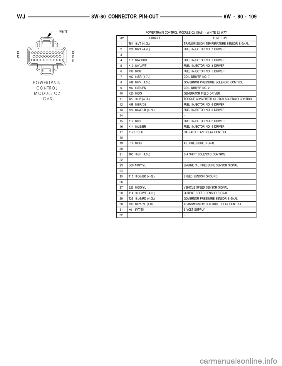
POWERTRAIN CONTROL MODULE C2 (GAS) - WHITE 32 WAY
CAV CIRCUIT FUNCTION
1 T54 18VT (4.0L) TRANSMISSION TEMPERATURE SENSOR SIGNAL
2 K26 18VT (4.7L) FUEL INJECTOR NO. 7 DRIVER
3- -
4 K11 18WT/DB FUEL INJECTOR NO. 1 DRIVER
5 K13 18YL/WT FUEL INJECTOR NO. 3 DRIVER
6 K38 18GY FUEL INJECTOR NO. 5 DRIVER
7 K97 14BR (4.7L) COIL DRIVER NO. 7
8 K88 18PK (4.0L) GOVERNOR PRESSURE SOLENOID CONTROL
9 K92 14TN/PK COIL DRIVER NO. 2
10 K20 18DG GENERATOR FIELD DRIVER
11 T20 18LB (4.0L) TORQUE CONVERTER CLUTCH SOLENOID CONTROL
12 K58 18BR/DB FUEL INJECTOR NO. 6 DRIVER
13 K28 18GY/LB (4.7L) FUEL INJECTOR NO. 8 DRIVER
14 - -
15 K12 18TN FUEL INJECTOR NO. 2 DRIVER
16 K14 18LB/BR FUEL INJECTOR NO. 4 DRIVER
17 K173 18LG RADIATOR FAN RELAY CONTROL
18 - -
19 C18 18DB A/C PRESSURE SIGNAL
20 - -
21 T60 18BR (4.0L) 3-4 SHIFT SOLENOID CONTROL
22 - -
23 G60 18GY/YL ENGINE OIL PRESSURE SENSOR SIGNAL
24 - -
25 T13 18DB/BK (4.0L) SPEED SENSOR GROUND
26 - -
27 B22 18DG/YL VEHICLE SPEED SENSOR SIGNAL
28 T14 18LG/WT (4.0L) OUTPUT SPEED SENSOR SIGNAL
29 T25 18LG/RD (4.0L) GOVERNOR PRESSURE SENSOR SIGNAL
30 K30 18PK/YL (4.0L) TRANSMISSION CONTROL RELAY CONTROL
31 K6 18VT/BK 5 VOLT SUPPLY
32 - -
WJ8W-80 CONNECTOR PIN-OUT 8W - 80 - 109
Page 1157 of 2199

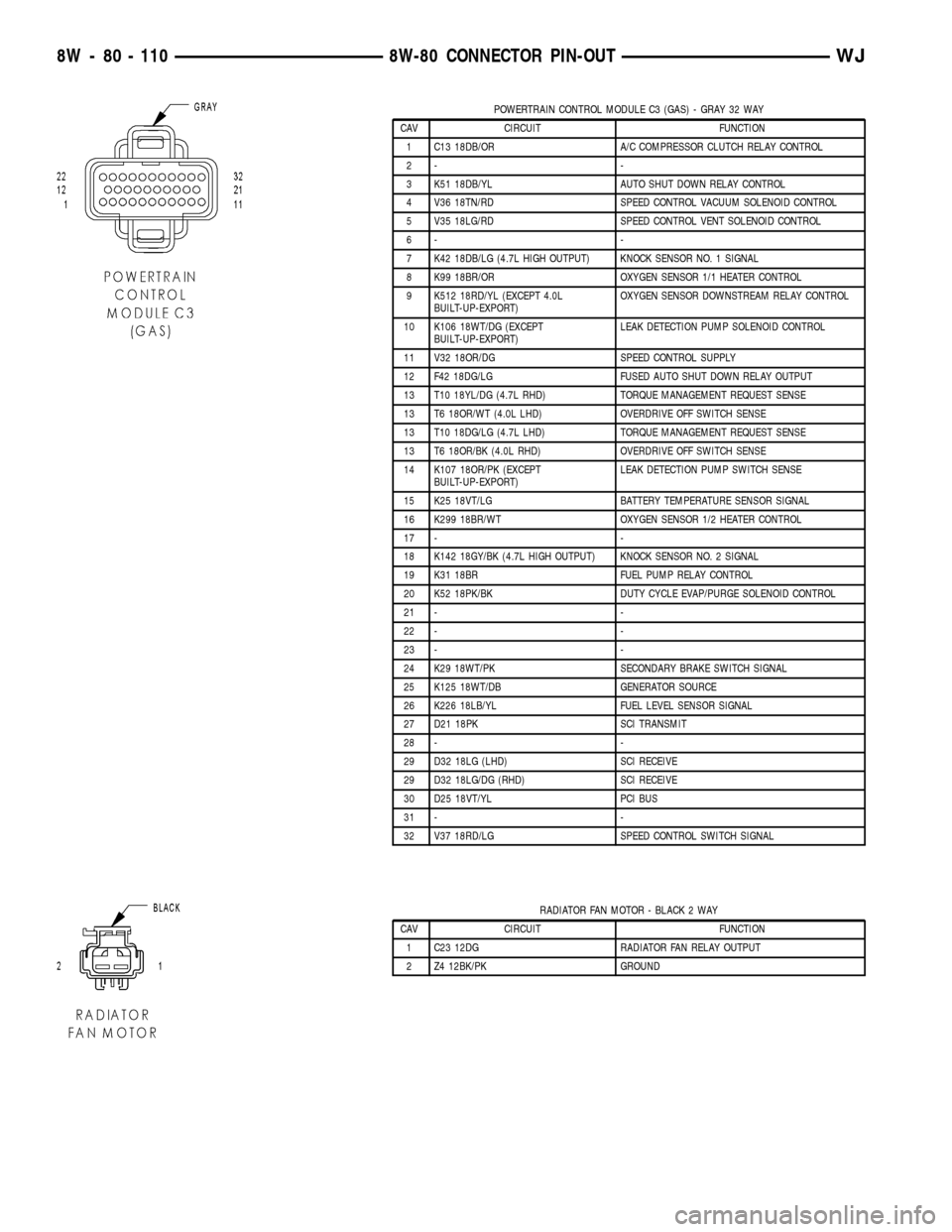
POWERTRAIN CONTROL MODULE C3 (GAS) - GRAY 32 WAY
CAV CIRCUIT FUNCTION
1 C13 18DB/OR A/C COMPRESSOR CLUTCH RELAY CONTROL
2- -
3 K51 18DB/YL AUTO SHUT DOWN RELAY CONTROL
4 V36 18TN/RD SPEED CONTROL VACUUM SOLENOID CONTROL
5 V35 18LG/RD SPEED CONTROL VENT SOLENOID CONTROL
6- -
7 K42 18DB/LG (4.7L HIGH OUTPUT) KNOCK SENSOR NO. 1 SIGNAL
8 K99 18BR/OR OXYGEN SENSOR 1/1 HEATER CONTROL
9 K512 18RD/YL (EXCEPT 4.0L
BUILT-UP-EXPORT)OXYGEN SENSOR DOWNSTREAM RELAY CONTROL
10 K106 18WT/DG (EXCEPT
BUILT-UP-EXPORT)LEAK DETECTION PUMP SOLENOID CONTROL
11 V32 18OR/DG SPEED CONTROL SUPPLY
12 F42 18DG/LG FUSED AUTO SHUT DOWN RELAY OUTPUT
13 T10 18YL/DG (4.7L RHD) TORQUE MANAGEMENT REQUEST SENSE
13 T6 18OR/WT (4.0L LHD) OVERDRIVE OFF SWITCH SENSE
13 T10 18DG/LG (4.7L LHD) TORQUE MANAGEMENT REQUEST SENSE
13 T6 18OR/BK (4.0L RHD) OVERDRIVE OFF SWITCH SENSE
14 K107 18OR/PK (EXCEPT
BUILT-UP-EXPORT)LEAK DETECTION PUMP SWITCH SENSE
15 K25 18VT/LG BATTERY TEMPERATURE SENSOR SIGNAL
16 K299 18BR/WT OXYGEN SENSOR 1/2 HEATER CONTROL
17 - -
18 K142 18GY/BK (4.7L HIGH OUTPUT) KNOCK SENSOR NO. 2 SIGNAL
19 K31 18BR FUEL PUMP RELAY CONTROL
20 K52 18PK/BK DUTY CYCLE EVAP/PURGE SOLENOID CONTROL
21 - -
22 - -
23 - -
24 K29 18WT/PK SECONDARY BRAKE SWITCH SIGNAL
25 K125 18WT/DB GENERATOR SOURCE
26 K226 18LB/YL FUEL LEVEL SENSOR SIGNAL
27 D21 18PK SCI TRANSMIT
28 - -
29 D32 18LG (LHD) SCI RECEIVE
29 D32 18LG/DG (RHD) SCI RECEIVE
30 D25 18VT/YL PCI BUS
31 - -
32 V37 18RD/LG SPEED CONTROL SWITCH SIGNAL
RADIATOR FAN MOTOR - BLACK 2 WAY
CAV CIRCUIT FUNCTION
1 C23 12DG RADIATOR FAN RELAY OUTPUT
2 Z4 12BK/PK GROUND
8W - 80 - 110 8W-80 CONNECTOR PIN-OUTWJ
Page 1312 of 2199

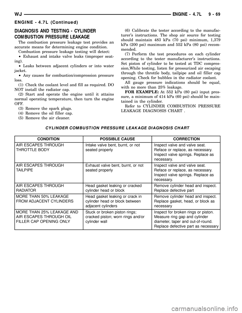
DIAGNOSIS AND TESTING - CYLINDER
COMBUSTION PRESSURE LEAKAGE
The combustion pressure leakage test provides an
accurate means for determining engine condition.
Combustion pressure leakage testing will detect:
²Exhaust and intake valve leaks (improper seat-
ing).
²Leaks between adjacent cylinders or into water
jacket.
²Any causes for combustion/compression pressure
loss.
(1) Check the coolant level and fill as required. DO
NOT install the radiator cap.
(2) Start and operate the engine until it attains
normal operating temperature, then turn the engine
OFF.
(3) Remove the spark plugs.
(4) Remove the oil filler cap.
(5) Remove the air cleaner.(6) Calibrate the tester according to the manufac-
turer's instructions. The shop air source for testing
should maintain 483 kPa (70 psi) minimum, 1,379
kPa (200 psi) maximum and 552 kPa (80 psi) recom-
mended.
(7) Perform the test procedures on each cylinder
according to the tester manufacturer's instructions.
Set piston of cylinder to be tested at TDC compres-
sion,While testing, listen for pressurized air escaping
through the throttle body, tailpipe and oil filler cap
opening. Check for bubbles in the radiator coolant.
All gauge pressure indications should be equal,
with no more than 25% leakage.
FOR EXAMPLE:At 552 kPa (80 psi) input pres-
sure, a minimum of 414 kPa (60 psi) should be main-
tained in the cylinder.
Refer to CYLINDER COMBUSTION PRESSURE
LEAKAGE DIAGNOSIS CHART .
CYLINDER COMBUSTION PRESSURE LEAKAGE DIAGNOSIS CHART
CONDITION POSSIBLE CAUSE CORRECTION
AIR ESCAPES THROUGH
THROTTLE BODYIntake valve bent, burnt, or not
seated properlyInspect valve and valve seat.
Reface or replace, as necessary.
Inspect valve springs. Replace as
necessary.
AIR ESCAPES THROUGH
TAILPIPEExhaust valve bent, burnt, or not
seated properlyInspect valve and valve seat.
Reface or replace, as necessary.
Inspect valve springs. Replace as
necessary.
AIR ESCAPES THROUGH
RADIATORHead gasket leaking or cracked
cylinder head or blockRemove cylinder head and inspect.
Replace defective part
MORE THAN 50% LEAKAGE
FROM ADJACENT CYLINDERSHead gasket leaking or crack in
cylinder head or block between
adjacent cylindersRemove cylinder head and inspect.
Replace gasket, head, or block as
necessary
MORE THAN 25% LEAKAGE AND
AIR ESCAPES THROUGH OIL
FILLER CAP OPENING ONLYStuck or broken piston rings;
cracked piston; worn rings and/or
cylinder wallInspect for broken rings or piston.
Measure ring gap and cylinder
diameter, taper and out-of-round.
Replace defective part as necessary
WJENGINE - 4.7L 9 - 69
ENGINE - 4.7L (Continued)