2003 JEEP GRAND CHEROKEE Battery
[x] Cancel search: BatteryPage 1057 of 2199
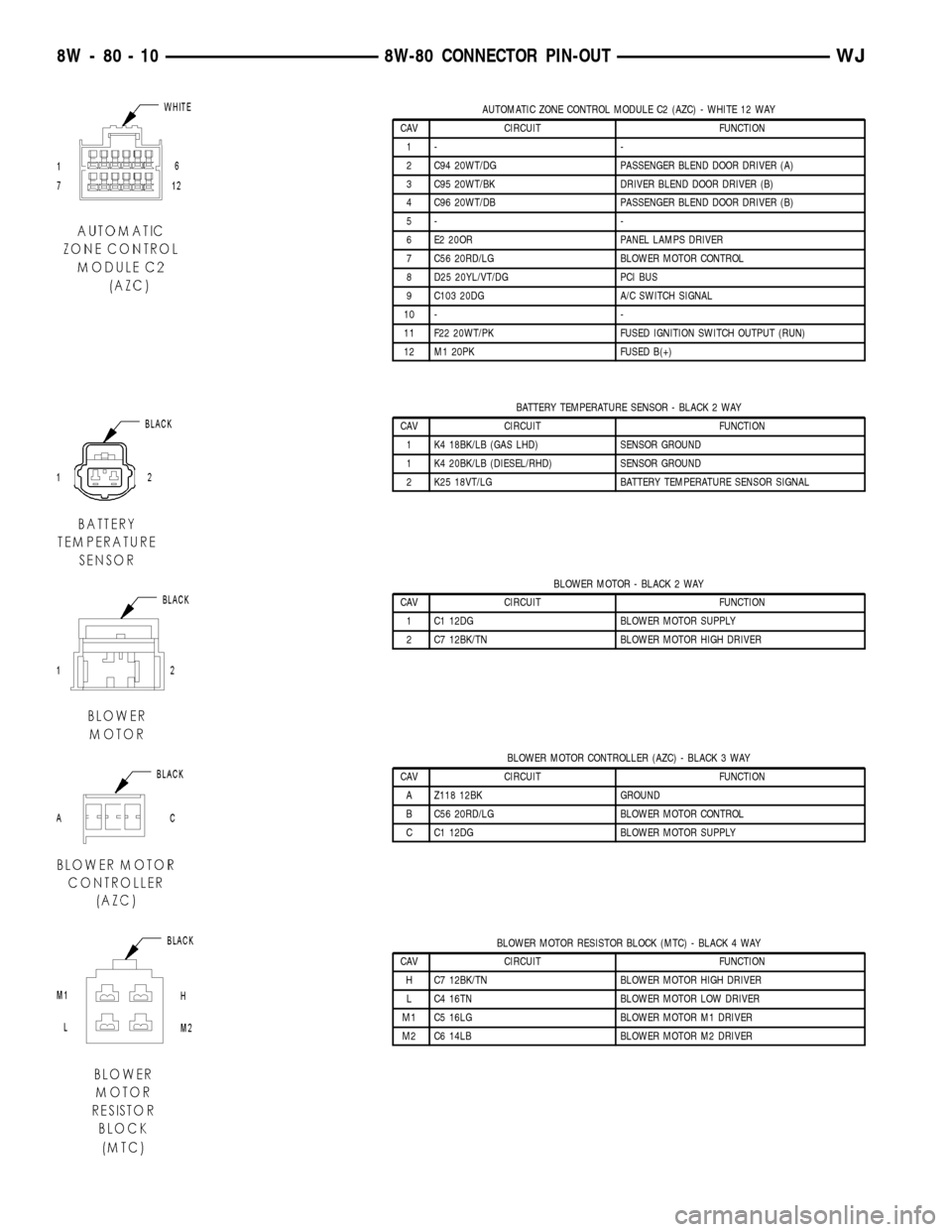
AUTOMATIC ZONE CONTROL MODULE C2 (AZC) - WHITE 12 WAY
CAV CIRCUIT FUNCTION
1- -
2 C94 20WT/DG PASSENGER BLEND DOOR DRIVER (A)
3 C95 20WT/BK DRIVER BLEND DOOR DRIVER (B)
4 C96 20WT/DB PASSENGER BLEND DOOR DRIVER (B)
5- -
6 E2 20OR PANEL LAMPS DRIVER
7 C56 20RD/LG BLOWER MOTOR CONTROL
8 D25 20YL/VT/DG PCI BUS
9 C103 20DG A/C SWITCH SIGNAL
10 - -
11 F22 20WT/PK FUSED IGNITION SWITCH OUTPUT (RUN)
12 M1 20PK FUSED B(+)
BATTERY TEMPERATURE SENSOR - BLACK 2 WAY
CAV CIRCUIT FUNCTION
1 K4 18BK/LB (GAS LHD) SENSOR GROUND
1 K4 20BK/LB (DIESEL/RHD) SENSOR GROUND
2 K25 18VT/LG BATTERY TEMPERATURE SENSOR SIGNAL
BLOWER MOTOR - BLACK 2 WAY
CAV CIRCUIT FUNCTION
1 C1 12DG BLOWER MOTOR SUPPLY
2 C7 12BK/TN BLOWER MOTOR HIGH DRIVER
BLOWER MOTOR CONTROLLER (AZC) - BLACK 3 WAY
CAV CIRCUIT FUNCTION
A Z118 12BK GROUND
B C56 20RD/LG BLOWER MOTOR CONTROL
C C1 12DG BLOWER MOTOR SUPPLY
BLOWER MOTOR RESISTOR BLOCK (MTC) - BLACK 4 WAY
CAV CIRCUIT FUNCTION
H C7 12BK/TN BLOWER MOTOR HIGH DRIVER
L C4 16TN BLOWER MOTOR LOW DRIVER
M1 C5 16LG BLOWER MOTOR M1 DRIVER
M2 C6 14LB BLOWER MOTOR M2 DRIVER
8W - 80 - 10 8W-80 CONNECTOR PIN-OUTWJ
Page 1059 of 2199
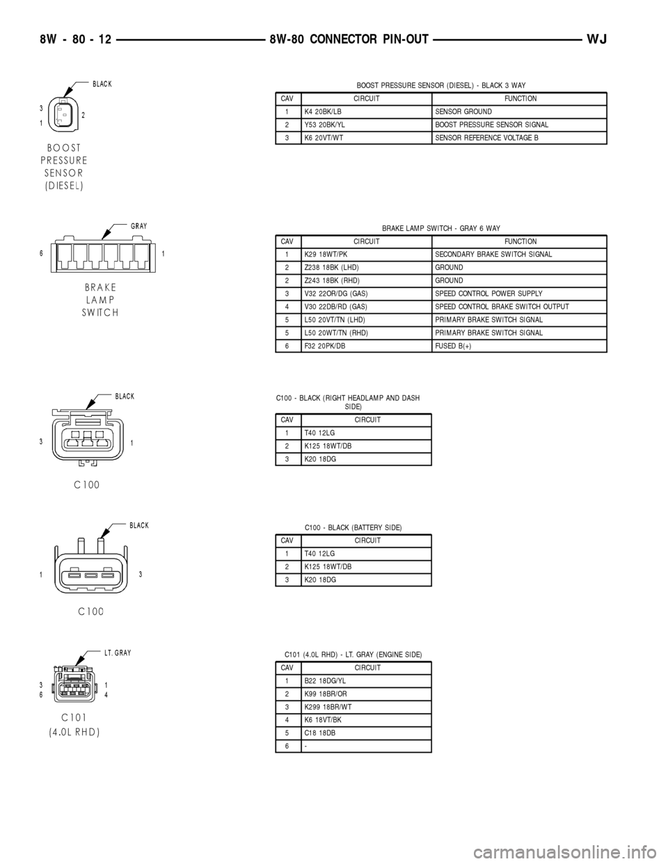
BOOST PRESSURE SENSOR (DIESEL) - BLACK 3 WAY
CAV CIRCUIT FUNCTION
1 K4 20BK/LB SENSOR GROUND
2 Y53 20BK/YL BOOST PRESSURE SENSOR SIGNAL
3 K6 20VT/WT SENSOR REFERENCE VOLTAGE B
BRAKE LAMP SWITCH - GRAY 6 WAY
CAV CIRCUIT FUNCTION
1 K29 18WT/PK SECONDARY BRAKE SWITCH SIGNAL
2 Z238 18BK (LHD) GROUND
2 Z243 18BK (RHD) GROUND
3 V32 22OR/DG (GAS) SPEED CONTROL POWER SUPPLY
4 V30 22DB/RD (GAS) SPEED CONTROL BRAKE SWITCH OUTPUT
5 L50 20VT/TN (LHD) PRIMARY BRAKE SWITCH SIGNAL
5 L50 20WT/TN (RHD) PRIMARY BRAKE SWITCH SIGNAL
6 F32 20PK/DB FUSED B(+)
C100 - BLACK (RIGHT HEADLAMP AND DASH
SIDE)
CAV CIRCUIT
1 T40 12LG
2 K125 18WT/DB
3 K20 18DG
C100 - BLACK (BATTERY SIDE)
CAV CIRCUIT
1 T40 12LG
2 K125 18WT/DB
3 K20 18DG
C101 (4.0L RHD) - LT. GRAY (ENGINE SIDE)
CAV CIRCUIT
1 B22 18DG/YL
2 K99 18BR/OR
3 K299 18BR/WT
4 K6 18VT/BK
5 C18 18DB
6-
8W - 80 - 12 8W-80 CONNECTOR PIN-OUTWJ
Page 1122 of 2199
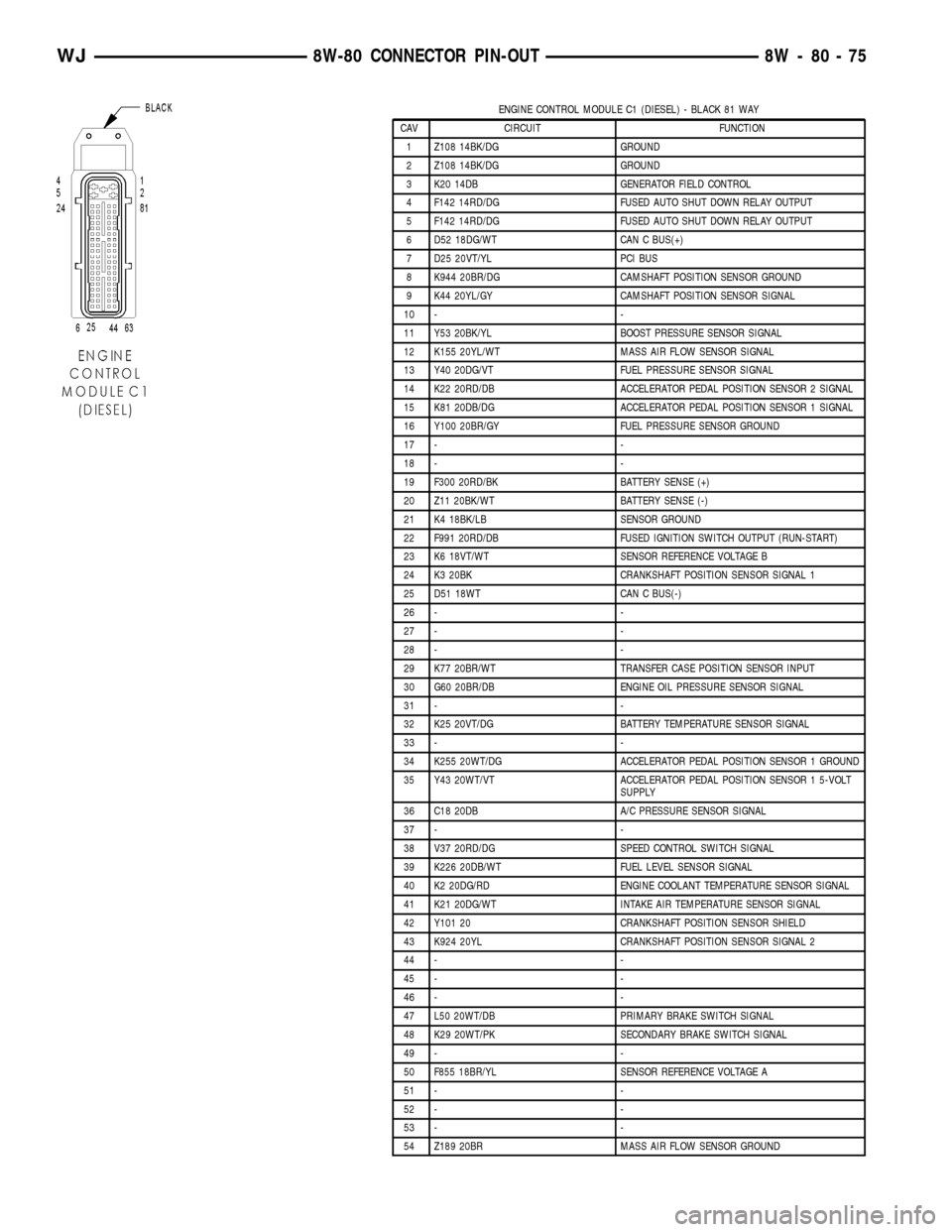
ENGINE CONTROL MODULE C1 (DIESEL) - BLACK 81 WAY
CAV CIRCUIT FUNCTION
1 Z108 14BK/DG GROUND
2 Z108 14BK/DG GROUND
3 K20 14DB GENERATOR FIELD CONTROL
4 F142 14RD/DG FUSED AUTO SHUT DOWN RELAY OUTPUT
5 F142 14RD/DG FUSED AUTO SHUT DOWN RELAY OUTPUT
6 D52 18DG/WT CAN C BUS(+)
7 D25 20VT/YL PCI BUS
8 K944 20BR/DG CAMSHAFT POSITION SENSOR GROUND
9 K44 20YL/GY CAMSHAFT POSITION SENSOR SIGNAL
10 - -
11 Y53 20BK/YL BOOST PRESSURE SENSOR SIGNAL
12 K155 20YL/WT MASS AIR FLOW SENSOR SIGNAL
13 Y40 20DG/VT FUEL PRESSURE SENSOR SIGNAL
14 K22 20RD/DB ACCELERATOR PEDAL POSITION SENSOR 2 SIGNAL
15 K81 20DB/DG ACCELERATOR PEDAL POSITION SENSOR 1 SIGNAL
16 Y100 20BR/GY FUEL PRESSURE SENSOR GROUND
17 - -
18 - -
19 F300 20RD/BK BATTERY SENSE (+)
20 Z11 20BK/WT BATTERY SENSE (-)
21 K4 18BK/LB SENSOR GROUND
22 F991 20RD/DB FUSED IGNITION SWITCH OUTPUT (RUN-START)
23 K6 18VT/WT SENSOR REFERENCE VOLTAGE B
24 K3 20BK CRANKSHAFT POSITION SENSOR SIGNAL 1
25 D51 18WT CAN C BUS(-)
26 - -
27 - -
28 - -
29 K77 20BR/WT TRANSFER CASE POSITION SENSOR INPUT
30 G60 20BR/DB ENGINE OIL PRESSURE SENSOR SIGNAL
31 - -
32 K25 20VT/DG BATTERY TEMPERATURE SENSOR SIGNAL
33 - -
34 K255 20WT/DG ACCELERATOR PEDAL POSITION SENSOR 1 GROUND
35 Y43 20WT/VT ACCELERATOR PEDAL POSITION SENSOR 1 5-VOLT
SUPPLY
36 C18 20DB A/C PRESSURE SENSOR SIGNAL
37 - -
38 V37 20RD/DG SPEED CONTROL SWITCH SIGNAL
39 K226 20DB/WT FUEL LEVEL SENSOR SIGNAL
40 K2 20DG/RD ENGINE COOLANT TEMPERATURE SENSOR SIGNAL
41 K21 20DG/WT INTAKE AIR TEMPERATURE SENSOR SIGNAL
42 Y101 20 CRANKSHAFT POSITION SENSOR SHIELD
43 K924 20YL CRANKSHAFT POSITION SENSOR SIGNAL 2
44 - -
45 - -
46 - -
47 L50 20WT/DB PRIMARY BRAKE SWITCH SIGNAL
48 K29 20WT/PK SECONDARY BRAKE SWITCH SIGNAL
49 - -
50 F855 18BR/YL SENSOR REFERENCE VOLTAGE A
51 - -
52 - -
53 - -
54 Z189 20BR MASS AIR FLOW SENSOR GROUND
WJ8W-80 CONNECTOR PIN-OUT 8W - 80 - 75
Page 1157 of 2199
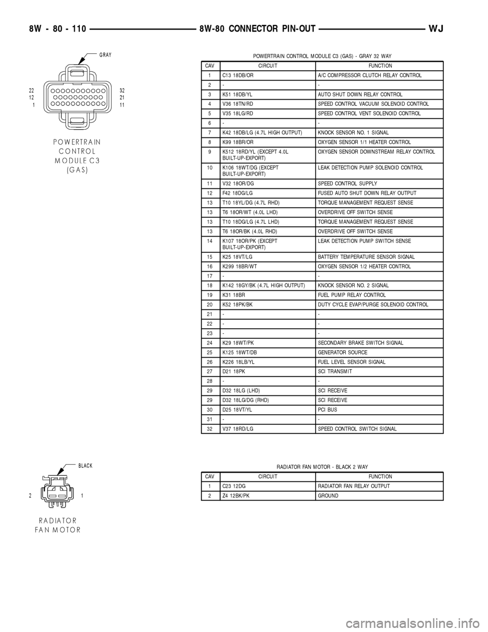
POWERTRAIN CONTROL MODULE C3 (GAS) - GRAY 32 WAY
CAV CIRCUIT FUNCTION
1 C13 18DB/OR A/C COMPRESSOR CLUTCH RELAY CONTROL
2- -
3 K51 18DB/YL AUTO SHUT DOWN RELAY CONTROL
4 V36 18TN/RD SPEED CONTROL VACUUM SOLENOID CONTROL
5 V35 18LG/RD SPEED CONTROL VENT SOLENOID CONTROL
6- -
7 K42 18DB/LG (4.7L HIGH OUTPUT) KNOCK SENSOR NO. 1 SIGNAL
8 K99 18BR/OR OXYGEN SENSOR 1/1 HEATER CONTROL
9 K512 18RD/YL (EXCEPT 4.0L
BUILT-UP-EXPORT)OXYGEN SENSOR DOWNSTREAM RELAY CONTROL
10 K106 18WT/DG (EXCEPT
BUILT-UP-EXPORT)LEAK DETECTION PUMP SOLENOID CONTROL
11 V32 18OR/DG SPEED CONTROL SUPPLY
12 F42 18DG/LG FUSED AUTO SHUT DOWN RELAY OUTPUT
13 T10 18YL/DG (4.7L RHD) TORQUE MANAGEMENT REQUEST SENSE
13 T6 18OR/WT (4.0L LHD) OVERDRIVE OFF SWITCH SENSE
13 T10 18DG/LG (4.7L LHD) TORQUE MANAGEMENT REQUEST SENSE
13 T6 18OR/BK (4.0L RHD) OVERDRIVE OFF SWITCH SENSE
14 K107 18OR/PK (EXCEPT
BUILT-UP-EXPORT)LEAK DETECTION PUMP SWITCH SENSE
15 K25 18VT/LG BATTERY TEMPERATURE SENSOR SIGNAL
16 K299 18BR/WT OXYGEN SENSOR 1/2 HEATER CONTROL
17 - -
18 K142 18GY/BK (4.7L HIGH OUTPUT) KNOCK SENSOR NO. 2 SIGNAL
19 K31 18BR FUEL PUMP RELAY CONTROL
20 K52 18PK/BK DUTY CYCLE EVAP/PURGE SOLENOID CONTROL
21 - -
22 - -
23 - -
24 K29 18WT/PK SECONDARY BRAKE SWITCH SIGNAL
25 K125 18WT/DB GENERATOR SOURCE
26 K226 18LB/YL FUEL LEVEL SENSOR SIGNAL
27 D21 18PK SCI TRANSMIT
28 - -
29 D32 18LG (LHD) SCI RECEIVE
29 D32 18LG/DG (RHD) SCI RECEIVE
30 D25 18VT/YL PCI BUS
31 - -
32 V37 18RD/LG SPEED CONTROL SWITCH SIGNAL
RADIATOR FAN MOTOR - BLACK 2 WAY
CAV CIRCUIT FUNCTION
1 C23 12DG RADIATOR FAN RELAY OUTPUT
2 Z4 12BK/PK GROUND
8W - 80 - 110 8W-80 CONNECTOR PIN-OUTWJ
Page 1176 of 2199
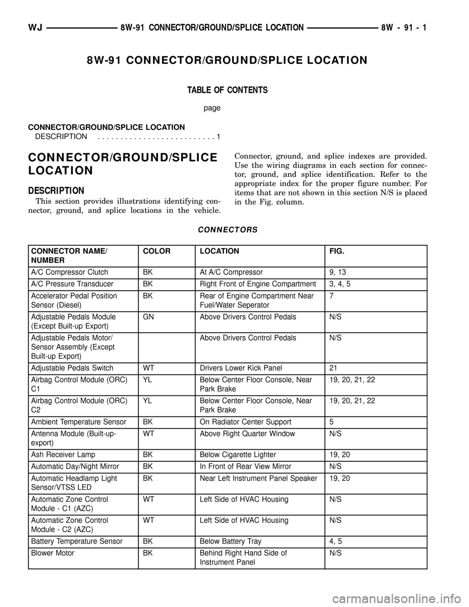
8W-91 CONNECTOR/GROUND/SPLICE LOCATION
TABLE OF CONTENTS
page
CONNECTOR/GROUND/SPLICE LOCATION
DESCRIPTION..........................1
CONNECTOR/GROUND/SPLICE
LOCATION
DESCRIPTION
This section provides illustrations identifying con-
nector, ground, and splice locations in the vehicle.Connector, ground, and splice indexes are provided.
Use the wiring diagrams in each section for connec-
tor, ground, and splice identification. Refer to the
appropriate index for the proper figure number. For
items that are not shown in this section N/S is placed
in the Fig. column.
CONNECTORS
CONNECTOR NAME/
NUMBERCOLOR LOCATION FIG.
A/C Compressor Clutch BK At A/C Compressor 9, 13
A/C Pressure Transducer BK Right Front of Engine Compartment 3, 4, 5
Accelerator Pedal Position
Sensor (Diesel)BK Rear of Engine Compartment Near
Fuel/Water Seperator7
Adjustable Pedals Module
(Except Built-up Export)GN Above Drivers Control Pedals N/S
Adjustable Pedals Motor/
Sensor Assembly (Except
Built-up Export)Above Drivers Control Pedals N/S
Adjustable Pedals Switch WT Drivers Lower Kick Panel 21
Airbag Control Module (ORC)
C1YL Below Center Floor Console, Near
Park Brake19, 20, 21, 22
Airbag Control Module (ORC)
C2YL Below Center Floor Console, Near
Park Brake19, 20, 21, 22
Ambient Temperature Sensor BK On Radiator Center Support 5
Antenna Module (Built-up-
export)WT Above Right Quarter Window N/S
Ash Receiver Lamp BK Below Cigarette Lighter 19, 20
Automatic Day/Night Mirror BK In Front of Rear View Mirror N/S
Automatic Headlamp Light
Sensor/VTSS LEDBK Near Left Instrument Panel Speaker 19, 20
Automatic Zone Control
Module - C1 (AZC)WT Left Side of HVAC Housing N/S
Automatic Zone Control
Module - C2 (AZC)WT Left Side of HVAC Housing N/S
Battery Temperature Sensor BK Below Battery Tray 4, 5
Blower Motor BK Behind Right Hand Side of
Instrument PanelN/S
WJ8W-91 CONNECTOR/GROUND/SPLICE LOCATION 8W - 91 - 1
Page 1186 of 2199
CONNECTOR NAME/
NUMBERCOLOR LOCATION FIG.
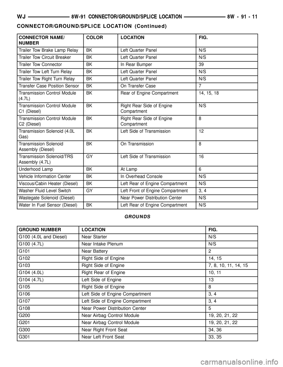
Trailer Tow Brake Lamp Relay BK Left Quarter Panel N/S
Trailer Tow Circuit Breaker BK Left Quarter Panel N/S
Trailer Tow Connector BK In Rear Bumper 39
Trailer Tow Left Turn Relay BK Left Quarter Panel N/S
Trailer Tow Right Turn Relay BK Left Quarter Panel N/S
Transfer Case Position Sensor BK On Transfer Case 7
Transmission Control Module
(4.7L)BK Rear of Engine Compartment 14, 15, 18
Transmission Control Module
C1 (Diesel)BK Right Rear Side of Engine
CompartmentN/S
Transmission Control Module
C2 (Diesel)BK Right Rear Side of Engine
Compartment8
Transmission Solenoid (4.0L
Gas)BK Left Side of Transmission 12
Transmission Solenoid
Assembly (Diesel)BK On Transmission 8
Transmission Solenoid/TRS
Assembly (4.7L)GY Left Side of Transmission 16
Underhood Lamp BK At Lamp 6
Vehicle Information Center BK In Overhead Console N/S
Viscous/Cabin Heater (Diesel) BK Left Rear of Engine Compartment N/S
Washer Fluid Level Switch GY Left Front of Engine Compartment 3, 4
Wastegate Solenoid (Diesel) Near Power Distribution Center N/S
Water In Fuel Sensor (Diesel) BK Left Rear of Engine Compartment N/S
GROUNDS
GROUND NUMBER LOCATION FIG.
G100 (4.0L and Diesel) Near Starter N/S
G100 (4.7L) Near Intake Plenum N/S
G101 Near Battery 2
G102 Right Side of Engine 14, 15
G103 Right Side of Engine 7, 8, 10, 11, 14, 15
G104 (4.0L) Right Rear of Engine 10, 11
G104 (4.7L) Left Side of Engine 13
G105 Right Side of Engine 8
G106 Left Side of Engine Compartment 3, 4
G107 Left Side of Engine Compartment 3, 4
G108 Near Power Distribution Center 5
G200 Near Airbag Control Module 19, 20, 21, 22
G201 Near Airbag Control Module 19, 20, 21, 22
G300 Near Right Front Seat 34, 36
G301 Near Left Front Seat 33, 35
WJ8W-91 CONNECTOR/GROUND/SPLICE LOCATION 8W - 91 - 11
CONNECTOR/GROUND/SPLICE LOCATION (Continued)
Page 1188 of 2199
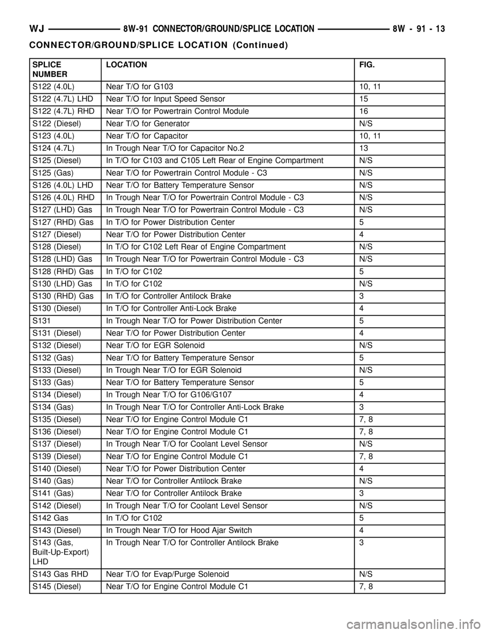
SPLICE
NUMBERLOCATION FIG.
S122 (4.0L) Near T/O for G103 10, 11
S122 (4.7L) LHD Near T/O for Input Speed Sensor 15
S122 (4.7L) RHD Near T/O for Powertrain Control Module 16
S122 (Diesel) Near T/O for Generator N/S
S123 (4.0L) Near T/O for Capacitor 10, 11
S124 (4.7L) In Trough Near T/O for Capacitor No.2 13
S125 (Diesel) In T/O for C103 and C105 Left Rear of Engine Compartment N/S
S125 (Gas) Near T/O for Powertrain Control Module - C3 N/S
S126 (4.0L) LHD Near T/O for Battery Temperature Sensor N/S
S126 (4.0L) RHD In Trough Near T/O for Powertrain Control Module - C3 N/S
S127 (LHD) Gas In Trough Near T/O for Powertrain Control Module - C3 N/S
S127 (RHD) Gas In T/O for Power Distribution Center 5
S127 (Diesel) Near T/O for Power Distribution Center 4
S128 (Diesel) In T/O for C102 Left Rear of Engine Compartment N/S
S128 (LHD) Gas In Trough Near T/O for Powertrain Control Module - C3 N/S
S128 (RHD) Gas In T/O for C102 5
S130 (LHD) Gas In T/O for C102 N/S
S130 (RHD) Gas In T/O for Controller Antilock Brake 3
S130 (Diesel) In T/O for Controller Anti-Lock Brake 4
S131 In Trough Near T/O for Power Distribution Center 5
S131 (Diesel) Near T/O for Power Distribution Center 4
S132 (Diesel) Near T/O for EGR Solenoid N/S
S132 (Gas) Near T/O for Battery Temperature Sensor 5
S133 (Diesel) In Trough Near T/O for EGR Solenoid N/S
S133 (Gas) Near T/O for Battery Temperature Sensor 5
S134 (Diesel) In Trough Near T/O for G106/G107 4
S134 (Gas) In Trough Near T/O for Controller Anti-Lock Brake 3
S135 (Diesel) Near T/O for Engine Control Module C1 7, 8
S136 (Diesel) Near T/O for Engine Control Module C1 7, 8
S137 (Diesel) In Trough Near T/O for Coolant Level Sensor N/S
S139 (Diesel) Near T/O for Engine Control Module C1 7, 8
S140 (Diesel) Near T/O for Power Distribution Center 4
S140 (Gas) Near T/O for Controller Antilock Brake N/S
S141 (Gas) Near T/O for Controller Antilock Brake 3
S142 (Diesel) In Trough Near T/O for Coolant Level Sensor N/S
S142 Gas In T/O for C102 5
S143 (Diesel) In Trough Near T/O for Hood Ajar Switch 4
S143 (Gas,
Built-Up-Export)
LHDIn Trough Near T/O for Controller Antilock Brake 3
S143 Gas RHD Near T/O for Evap/Purge Solenoid N/S
S145 (Diesel) Near T/O for Engine Control Module C1 7, 8
WJ8W-91 CONNECTOR/GROUND/SPLICE LOCATION 8W - 91 - 13
CONNECTOR/GROUND/SPLICE LOCATION (Continued)
Page 1194 of 2199

Fig. 2 ENGINE COMPARTMENT (BATTERY)
WJ8W-91 CONNECTOR/GROUND/SPLICE LOCATION 8W - 91 - 19
CONNECTOR/GROUND/SPLICE LOCATION (Continued)