2003 JEEP GRAND CHEROKEE seat
[x] Cancel search: seatPage 127 of 2199
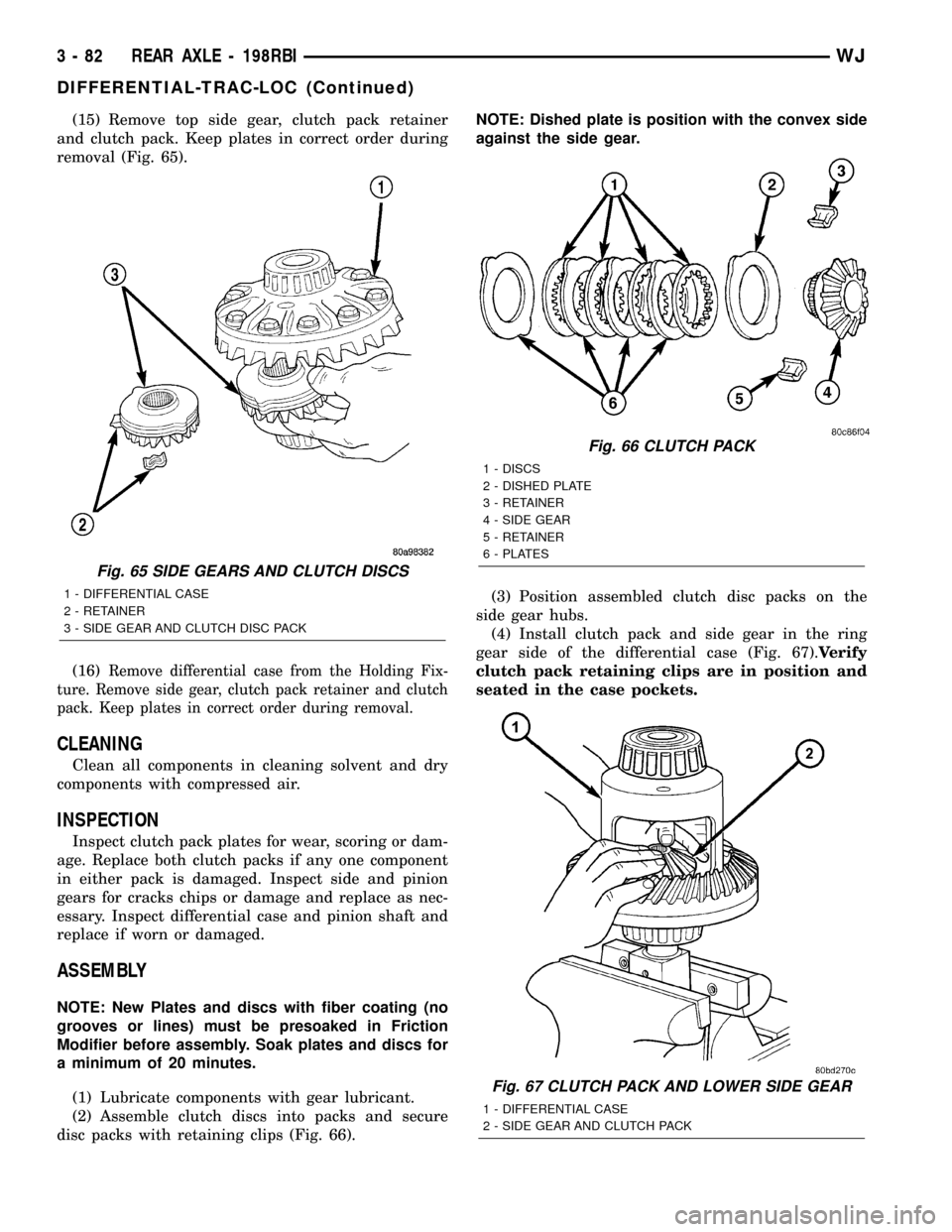
(15) Remove top side gear, clutch pack retainer
and clutch pack. Keep plates in correct order during
removal (Fig. 65).
(16)
Remove differential case from the Holding Fix-
ture. Remove side gear, clutch pack retainer and clutch
pack. Keep plates in correct order during removal.
CLEANING
Clean all components in cleaning solvent and dry
components with compressed air.
INSPECTION
Inspect clutch pack plates for wear, scoring or dam-
age. Replace both clutch packs if any one component
in either pack is damaged. Inspect side and pinion
gears for cracks chips or damage and replace as nec-
essary. Inspect differential case and pinion shaft and
replace if worn or damaged.
ASSEMBLY
NOTE: New Plates and discs with fiber coating (no
grooves or lines) must be presoaked in Friction
Modifier before assembly. Soak plates and discs for
a minimum of 20 minutes.
(1) Lubricate components with gear lubricant.
(2) Assemble clutch discs into packs and secure
disc packs with retaining clips (Fig. 66).NOTE: Dished plate is position with the convex side
against the side gear.
(3) Position assembled clutch disc packs on the
side gear hubs.
(4) Install clutch pack and side gear in the ring
gear side of the differential case (Fig. 67).Verify
clutch pack retaining clips are in position and
seated in the case pockets.
Fig. 65 SIDE GEARS AND CLUTCH DISCS
1 - DIFFERENTIAL CASE
2 - RETAINER
3 - SIDE GEAR AND CLUTCH DISC PACK
Fig. 66 CLUTCH PACK
1 - DISCS
2 - DISHED PLATE
3 - RETAINER
4 - SIDE GEAR
5 - RETAINER
6 - PLATES
Fig. 67 CLUTCH PACK AND LOWER SIDE GEAR
1 - DIFFERENTIAL CASE
2 - SIDE GEAR AND CLUTCH PACK
3 - 82 REAR AXLE - 198RBIWJ
DIFFERENTIAL-TRAC-LOC (Continued)
Page 132 of 2199

(1) Apply Mopar Door Ease or equivalent lubricant
to outside surface of the pinion bearing cups.
(2) Install pinion rear bearing cup with Installer
D-146 and Driver Handle C-4171 (Fig. 80) and verify
cup is seated.
(3) Install pinion front bearing cup with Installer
D-130 and Handle C-4171 (Fig. 81) and verify cup is
seated.(4) Install pinion front bearing and oil slinger, if
equipped.
(5) Apply a light coating of gear lubricant on the
lip of pinion seal. Install seal with an appropriate
installer (Fig. 82).
(6) Install depth shim on the pinion gear.
(7) Install rear bearing and slinger if equipped, on
the pinion gear with Installer W-262 and a press
(Fig. 83).
Fig. 80 REAR PINION BEARING CUP
1 - INSTALLER
2 - HANDLE
Fig. 81 FRONT PINION BEARING CUP
1 - INSTALLER
2 - HANDLE
Fig. 82 PINION SEAL INSTALLER
1 - HANDLE
2 - INSTALLER
Fig. 83 REAR PINION BEARING
1 - PRESS
2 - INSTALLER
3 - PINION GEAR
4 - PINION BEARING
WJREAR AXLE - 198RBI 3 - 87
PINION GEAR/RING GEAR (Continued)
Page 145 of 2199
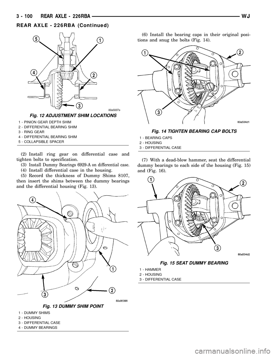
(2) Install ring gear on differential case and
tighten bolts to specification.
(3)
Install Dummy Bearings 6929-A on differential case.
(4) Install differential case in the housing.
(5) Record the thickness of Dummy Shims 8107,
then insert the shims between the dummy bearings
and the differential housing (Fig. 13).(6) Install the bearing caps in their original posi-
tions and snug the bolts (Fig. 14).
(7) With a dead-blow hammer, seat the differential
dummy bearings to each side of the housing (Fig. 15)
and (Fig. 16).
Fig. 12 ADJUSTMENT SHIM LOCATIONS
1 - PINION GEAR DEPTH SHIM
2 - DIFFERENTIAL BEARING SHIM
3 - RING GEAR
4 - DIFFERENTIAL BEARING SHIM
5 - COLLAPSIBLE SPACER
Fig. 13 DUMMY SHIM POINT
1 - DUMMY SHIMS
2 - HOUSING
3 - DIFFERENTIAL CASE
4 - DUMMY BEARINGS
Fig. 14 TIGHTEN BEARING CAP BOLTS
1 - BEARING CAPS
2 - HOUSING
3 - DIFFERENTIAL CASE
Fig. 15 SEAT DUMMY BEARING
1 - HAMMER
2 - HOUSING
3 - DIFFERENTIAL CASE
3 - 100 REAR AXLE - 226RBAWJ
REAR AXLE - 226RBA (Continued)
Page 146 of 2199
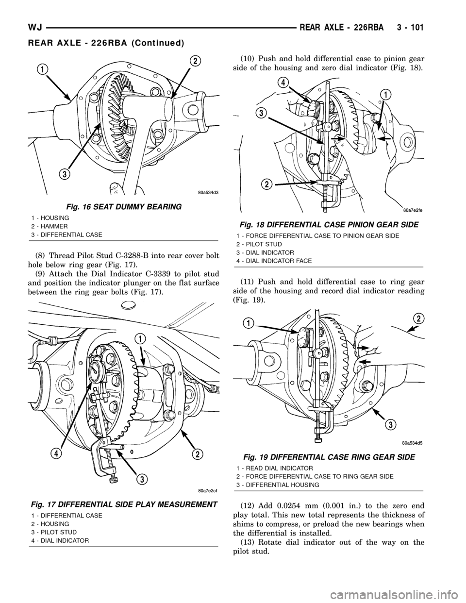
(8) Thread Pilot Stud C-3288-B into rear cover bolt
hole below ring gear (Fig. 17).
(9) Attach the Dial Indicator C-3339 to pilot stud
and position the indicator plunger on the flat surface
between the ring gear bolts (Fig. 17).(10) Push and hold differential case to pinion gear
side of the housing and zero dial indicator (Fig. 18).
(11) Push and hold differential case to ring gear
side of the housing and record dial indicator reading
(Fig. 19).
(12) Add 0.0254 mm (0.001 in.) to the zero end
play total. This new total represents the thickness of
shims to compress, or preload the new bearings when
the differential is installed.
(13) Rotate dial indicator out of the way on the
pilot stud.
Fig. 16 SEAT DUMMY BEARING
1 - HOUSING
2 - HAMMER
3 - DIFFERENTIAL CASE
Fig. 17 DIFFERENTIAL SIDE PLAY MEASUREMENT
1 - DIFFERENTIAL CASE
2 - HOUSING
3 - PILOT STUD
4 - DIAL INDICATOR
Fig. 18 DIFFERENTIAL CASE PINION GEAR SIDE
1 - FORCE DIFFERENTIAL CASE TO PINION GEAR SIDE
2 - PILOT STUD
3 - DIAL INDICATOR
4 - DIAL INDICATOR FACE
Fig. 19 DIFFERENTIAL CASE RING GEAR SIDE
1 - READ DIAL INDICATOR
2 - FORCE DIFFERENTIAL CASE TO RING GEAR SIDE
3 - DIFFERENTIAL HOUSING
WJREAR AXLE - 226RBA 3 - 101
REAR AXLE - 226RBA (Continued)
Page 147 of 2199
(14) Remove differential case and dummy bearings
from the housing.
(15) Install the pinion gear in the housing. Install
the pinion yoke and establish the correct pinion
rotating torque.
(16) Install differential case and Dummy Bearings
6929-A in the housing.
(17) Install a single dummy shim in the ring gear
side. Install bearing caps and tighten bolts snug.
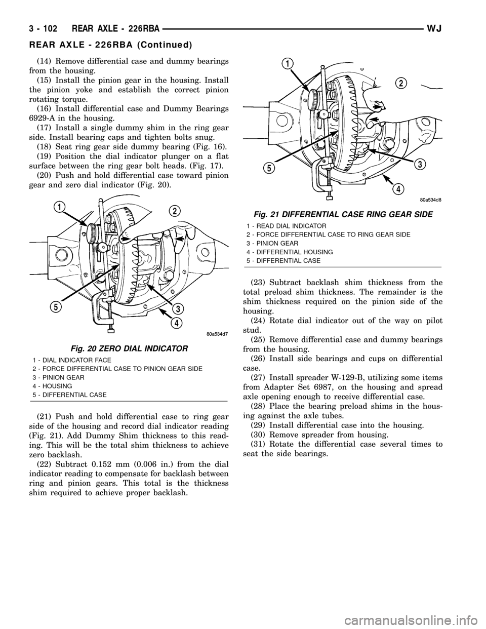
(18) Seat ring gear side dummy bearing (Fig. 16).
(19) Position the dial indicator plunger on a flat
surface between the ring gear bolt heads. (Fig. 17).
(20) Push and hold differential case toward pinion
gear and zero dial indicator (Fig. 20).
(21) Push and hold differential case to ring gear
side of the housing and record dial indicator reading
(Fig. 21). Add Dummy Shim thickness to this read-
ing. This will be the total shim thickness to achieve
zero backlash.
(22) Subtract 0.152 mm (0.006 in.) from the dial
indicator reading to compensate for backlash between
ring and pinion gears. This total is the thickness
shim required to achieve proper backlash.(23) Subtract backlash shim thickness from the
total preload shim thickness. The remainder is the
shim thickness required on the pinion side of the
housing.
(24) Rotate dial indicator out of the way on pilot
stud.
(25) Remove differential case and dummy bearings
from the housing.
(26) Install side bearings and cups on differential
case.
(27) Install spreader W-129-B, utilizing some items
from Adapter Set 6987, on the housing and spread
axle opening enough to receive differential case.
(28) Place the bearing preload shims in the hous-
ing against the axle tubes.
(29) Install differential case into the housing.
(30) Remove spreader from housing.
(31) Rotate the differential case several times to
seat the side bearings.
Fig. 20 ZERO DIAL INDICATOR
1 - DIAL INDICATOR FACE
2 - FORCE DIFFERENTIAL CASE TO PINION GEAR SIDE
3 - PINION GEAR
4 - HOUSING
5 - DIFFERENTIAL CASE
Fig. 21 DIFFERENTIAL CASE RING GEAR SIDE
1 - READ DIAL INDICATOR
2 - FORCE DIFFERENTIAL CASE TO RING GEAR SIDE
3 - PINION GEAR
4 - DIFFERENTIAL HOUSING
5 - DIFFERENTIAL CASE
3 - 102 REAR AXLE - 226RBAWJ
REAR AXLE - 226RBA (Continued)
Page 162 of 2199
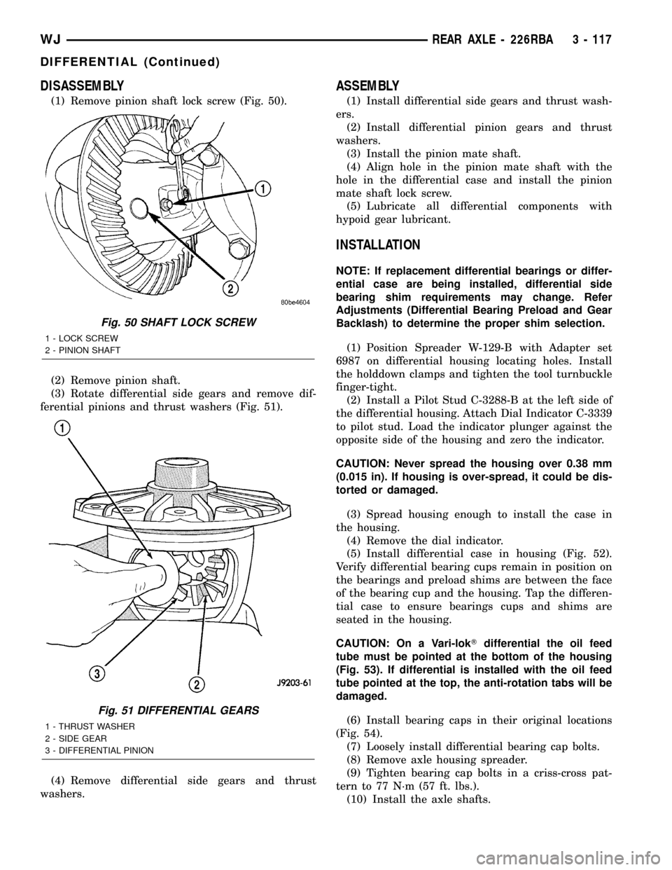
DISASSEMBLY
(1) Remove pinion shaft lock screw (Fig. 50).
(2) Remove pinion shaft.
(3) Rotate differential side gears and remove dif-
ferential pinions and thrust washers (Fig. 51).
(4) Remove differential side gears and thrust
washers.
ASSEMBLY
(1) Install differential side gears and thrust wash-
ers.
(2) Install differential pinion gears and thrust
washers.
(3) Install the pinion mate shaft.
(4) Align hole in the pinion mate shaft with the
hole in the differential case and install the pinion
mate shaft lock screw.
(5) Lubricate all differential components with
hypoid gear lubricant.
INSTALLATION
NOTE: If replacement differential bearings or differ-
ential case are being installed, differential side
bearing shim requirements may change. Refer
Adjustments (Differential Bearing Preload and Gear
Backlash) to determine the proper shim selection.
(1) Position Spreader W-129-B with Adapter set
6987 on differential housing locating holes. Install
the holddown clamps and tighten the tool turnbuckle
finger-tight.
(2) Install a Pilot Stud C-3288-B at the left side of
the differential housing. Attach Dial Indicator C-3339
to pilot stud. Load the indicator plunger against the
opposite side of the housing and zero the indicator.
CAUTION: Never spread the housing over 0.38 mm
(0.015 in). If housing is over-spread, it could be dis-
torted or damaged.
(3) Spread housing enough to install the case in
the housing.
(4) Remove the dial indicator.
(5) Install differential case in housing (Fig. 52).
Verify differential bearing cups remain in position on
the bearings and preload shims are between the face
of the bearing cup and the housing. Tap the differen-
tial case to ensure bearings cups and shims are
seated in the housing.
CAUTION: On a Vari-lokTdifferential the oil feed
tube must be pointed at the bottom of the housing
(Fig. 53). If differential is installed with the oil feed
tube pointed at the top, the anti-rotation tabs will be
damaged.
(6) Install bearing caps in their original locations
(Fig. 54).
(7) Loosely install differential bearing cap bolts.
(8) Remove axle housing spreader.
(9) Tighten bearing cap bolts in a criss-cross pat-
tern to 77 N´m (57 ft. lbs.).
(10) Install the axle shafts.
Fig. 50 SHAFT LOCK SCREW
1 - LOCK SCREW
2 - PINION SHAFT
Fig. 51 DIFFERENTIAL GEARS
1 - THRUST WASHER
2 - SIDE GEAR
3 - DIFFERENTIAL PINION
WJREAR AXLE - 226RBA 3 - 117
DIFFERENTIAL (Continued)
Page 167 of 2199
damaged. Inspect side gears and pinions. Replace
any gear that is worn, cracked, chipped or damaged.
Inspect differential case and pinion shaft. Replace if
worn or damaged.
NOTE: New Plates and discs with fiber coating (no
grooves or lines) must be presoaked in Friction
Modifier before assembly. Soak plates and discs for
a minimum of 20 minutes.
(1) Lubricate each component with gear lubricant
before assembly.
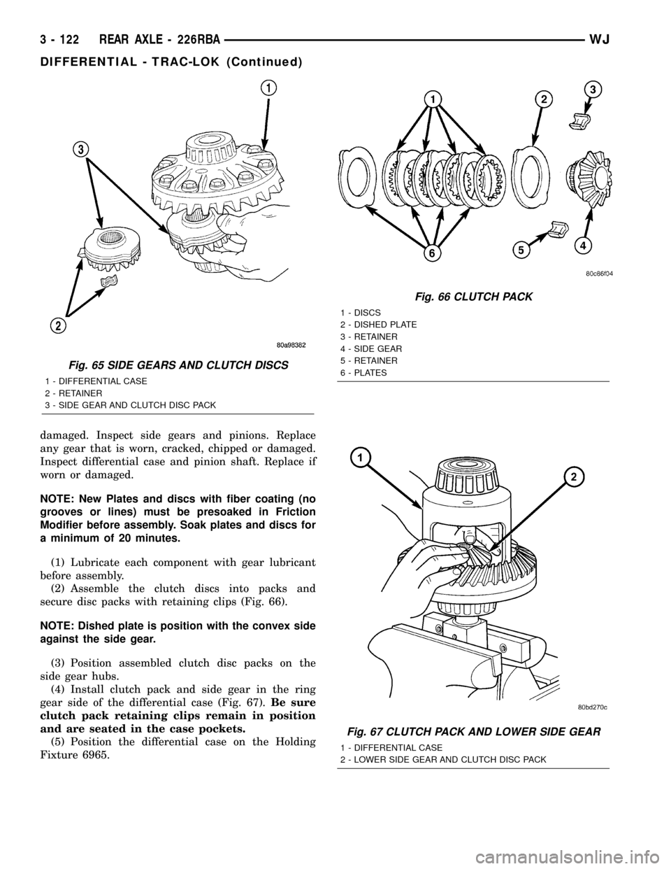
(2) Assemble the clutch discs into packs and
secure disc packs with retaining clips (Fig. 66).
NOTE: Dished plate is position with the convex side
against the side gear.
(3) Position assembled clutch disc packs on the
side gear hubs.
(4) Install clutch pack and side gear in the ring
gear side of the differential case (Fig. 67).Be sure
clutch pack retaining clips remain in position
and are seated in the case pockets.
(5) Position the differential case on the Holding
Fixture 6965.
Fig. 65 SIDE GEARS AND CLUTCH DISCS
1 - DIFFERENTIAL CASE
2 - RETAINER
3 - SIDE GEAR AND CLUTCH DISC PACK
Fig. 66 CLUTCH PACK
1 - DISCS
2 - DISHED PLATE
3 - RETAINER
4 - SIDE GEAR
5 - RETAINER
6 - PLATES
Fig. 67 CLUTCH PACK AND LOWER SIDE GEAR
1 - DIFFERENTIAL CASE
2 - LOWER SIDE GEAR AND CLUTCH DISC PACK
3 - 122 REAR AXLE - 226RBAWJ
DIFFERENTIAL - TRAC-LOK (Continued)
Page 169 of 2199
CAUTION: Vari-lokTplenum must be seated against
the differential case prior to installing the ring gear
side differential bearing.
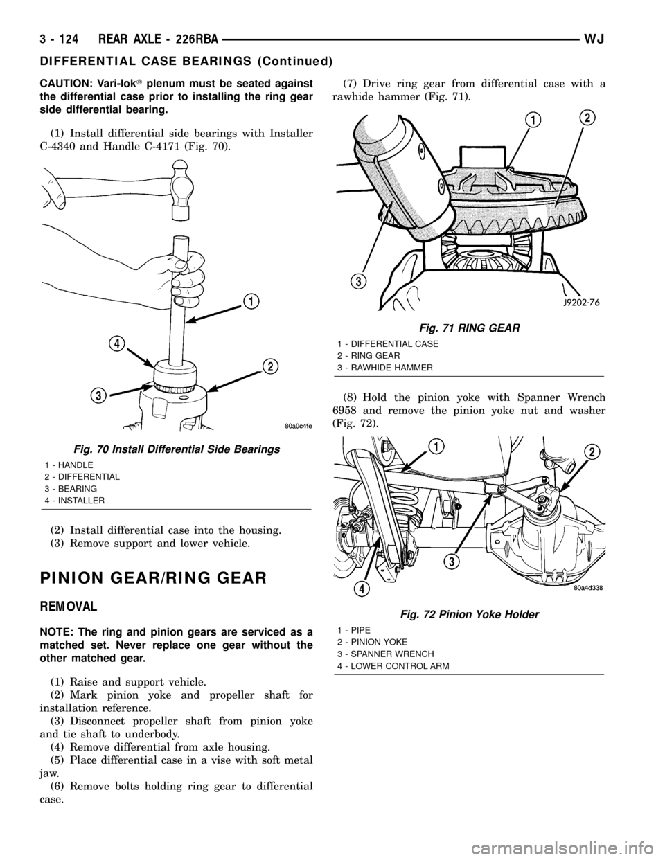
(1) Install differential side bearings with Installer
C-4340 and Handle C-4171 (Fig. 70).
(2) Install differential case into the housing.
(3) Remove support and lower vehicle.
PINION GEAR/RING GEAR
REMOVAL
NOTE: The ring and pinion gears are serviced as a
matched set. Never replace one gear without the
other matched gear.
(1) Raise and support vehicle.
(2) Mark pinion yoke and propeller shaft for
installation reference.
(3) Disconnect propeller shaft from pinion yoke
and tie shaft to underbody.
(4) Remove differential from axle housing.
(5) Place differential case in a vise with soft metal
jaw.
(6) Remove bolts holding ring gear to differential
case.(7) Drive ring gear from differential case with a
rawhide hammer (Fig. 71).
(8) Hold the pinion yoke with Spanner Wrench
6958 and remove the pinion yoke nut and washer
(Fig. 72).
Fig. 70 Install Differential Side Bearings
1 - HANDLE
2 - DIFFERENTIAL
3 - BEARING
4 - INSTALLER
Fig. 71 RING GEAR
1 - DIFFERENTIAL CASE
2 - RING GEAR
3 - RAWHIDE HAMMER
Fig. 72 Pinion Yoke Holder
1 - PIPE
2 - PINION YOKE
3 - SPANNER WRENCH
4 - LOWER CONTROL ARM
3 - 124 REAR AXLE - 226RBAWJ
DIFFERENTIAL CASE BEARINGS (Continued)