2003 JEEP GRAND CHEROKEE manual neutral
[x] Cancel search: manual neutralPage 706 of 2199

8W-12 JUNCTION BLOCK
Component PageA/C Compressor Clutch Relay................8W-12-18
Accessory Delay Relay.....................8W-12-25
Adjustable Pedals Module..................8W-12-11
Airbag Control Module....................8W-12-25
Auto Shut Down Relay....................8W-12-18
Automatic Day/Night Mirror.................8W-12-23
Automatic Headlamp Light Sensor/VTSS LED......8W-12-15
Automatic Zone Control Module..........8W-12-15, 17, 22
Back-Up Lamp Relay.....................8W-12-22
Body Control Module . . . 8W-12-10, 12, 13, 15, 17, 20, 23, 24, 25,
26, 27, 28, 29, 30, 31, 35, 36
Brake Lamp Switch......................8W-12-24
Cargo Lamp......................8W-12-16, 24, 27
Cigar Lighter..........................8W-12-17
Cigar Lighter Relay....................8W-12-17, 26
Circuit Breaker No. 1...................8W-12-28, 29
Circuit Breaker No. 2......................8W-12-9
Clockspring...........................8W-12-31
Combination Flasher............8W-12-10, 22, 27, 32, 35
Controller Antilock Brake..................8W-12-21
Data Link Connector.....................8W-12-10
Driver Door Module......................8W-12-34
Driver Heated Seat Switch..................8W-12-22
Driver Lumbar Switch.....................8W-12-9
Driver Power Seat Switch...................8W-12-9
Electric Brake..........................8W-12-21
Engine Control Module....................8W-12-19
Engine Starter Motor Relay.................8W-12-26
EVAP/Purge Solenoid.....................8W-12-18
Fog Lamp Relay........................8W-12-24
Front Power Outlet......................8W-12-11
Front Wiper Motor....................8W-12-28, 29
Fuel Pump Relay........................8W-12-18
Fuse 2..............................8W-12-17
Fuse 3............................8W-12-10, 20
Fuse 4..............................8W-12-10
Fuse 5..............................8W-12-11
Fuse 6............................8W-12-12, 13
Fuse 7..............................8W-12-15
Fuse 8..............................8W-12-16
Fuse 9..............................8W-12-11
Fuse 10..............................8W-12-11
Fuse 11..............................8W-12-17
Fuse 12.......................8W-12-18, 19, 21, 34
Fuse 14..............................8W-12-20
Fuse 15.........................8W-12-11, 15, 20
Fuse 16..............................8W-12-10
Fuse 17..............................8W-12-10
Fuse 18...........................8W-12-21, 34
Fuse 19..............................8W-12-21
Fuse 20..............................8W-12-22
Fuse 21...........................8W-12-18, 19
Fuse 22..............................8W-12-23
Fuse 23..............................8W-12-24
Fuse 24..............................8W-12-24
Fuse 25..............................8W-12-25
Fuse 26..............................8W-12-17
Fuse 27..............................8W-12-36
Fuse 28..............................8W-12-26
Fuse 29..............................8W-12-26
Fuse 30..............................8W-12-26
Fuse 31..............................8W-12-26
Fuse 32..............................8W-12-25
Fuse 33..............................8W-12-25
G200...............................8W-12-35
Glove Box Lamp........................8W-12-16
Headlamp Leveling Switch...............8W-12-12, 13
High Beam Relay........................8W-12-10
Horn Relay...........................8W-12-31
Horn Switch...........................8W-12-31
Instrument Cluster..................8W-12-10, 23, 32
Intrusion Transceiver Module................8W-12-16
Junction Block.........8W-12-2, 3, 9, 10, 11, 12, 13, 15, 16,
17, 18, 19, 20, 21, 22, 23, 24, 25,
26, 27, 28, 29, 30, 31, 32, 34, 35, 36Component PageLeft Courtesy Lamp......................8W-12-16
Left Door Handle Courtesy Lamp.........8W-12-16, 24, 30
Left Fog Lamp.........................8W-12-24
Left Front Park Lamp.....................8W-12-14
Left Front Park/Turn Signal Lamp...........8W-12-14, 33
Left Front Side Marker Lamp..............8W-12-14, 33
Left Front Turn Signal Lamp................8W-12-33
Left Headlamp Leveling Motor...............8W-12-14
Left High Beam Headlamp..................8W-12-10
Left Liftgate Ajar Switch...................8W-12-30
Left Low Beam Headlamp..................8W-12-20
Left Multi-Function Switch...............8W-12-10, 35
Left Rear Door Lock Motor/Ajar Switch..........8W-12-27
Left Rear Lamp Assembly...........8W-12-12, 13, 27, 36
Left Side Repeater Lamp...................8W-12-32
Left Visor/Vanity Lamp..................8W-12-16, 30
License Lamp No. 1....................8W-12-12, 13
License Lamp No. 2....................8W-12-12, 13
Liftgate Flip-Up Ajar Switch.................8W-12-30
Liftgate Flip-Up Push Button Switch...........8W-12-16
Liftgate Power Lock Motor..................8W-12-16
Low Beam Relay........................8W-12-20
Low Beam/Daytime Running Lamp Relay.........8W-12-20
Manual Temperature Control..............8W-12-17, 22
Overhead Map/Courtesy Lamp...........8W-12-16, 24, 30
Park Lamp Relay.....................8W-12-12, 13
Park/Neutral Position Switch................8W-12-22
Passenger Door Module....................8W-12-34
Passenger Heated Seat Switch...............8W-12-22
Passenger Lumbar Switch...................8W-12-9
Passenger Power Seat Switch.................8W-12-9
Power Amplifier.........................8W-12-11
Power Connector........................8W-12-11
Power Distribution Center....8W-12-10, 11, 15, 17, 20, 21, 34
Powertrain Control Module.................8W-12-18
Radio.............................8W-12-11, 26
Rain Sensor...........................8W-12-25
Rear Window Defogger....................8W-12-17
Rear Window Defogger Relay................8W-12-17
Rear Wiper Motor.....................8W-12-16, 30
Remote Keyless Module....................8W-12-15
Right Courtesy Lamp.....................8W-12-16
Right Door Handle Courtesy Lamp........8W-12-16, 24, 30
Right Fog Lamp........................8W-12-24
Right Front Park Lamp....................8W-12-14
Right Front Park/Turn Signal Lamp..........8W-12-14, 33
Right Front Side Marker Lamp.............8W-12-14, 33
Right Front Turn Signal Lamp...............8W-12-33
Right Headlamp Leveling Motor..............8W-12-14
Right High Beam Headlamp.................8W-12-10
Right Liftgate Ajar Switch..................8W-12-30
Right Low Beam Headlamp.................8W-12-20
Right Multi-Function Switch.................8W-12-26
Right Rear Lamp Assembly..........8W-12-12, 13, 32, 36
Right Side Repeater Lamp..................8W-12-32
Right Visor/Vanity Lamp.................8W-12-16, 30
Seat Module...........................8W-12-9
Sentry Key Immobilizer Module............8W-12-15, 23
Shifter Assembly......................8W-12-18, 19
Siren...............................8W-12-15
Sunroof Control Module....................8W-12-25
Temperature Valve Actuator.................8W-12-22
Trailer Tow Brake Lamp Relay...............8W-12-21
Trailer Tow Circuit Breaker.................8W-12-17
Trailer Tow Connector.....................8W-12-12
Trailer Tow Left Turn Relay.................8W-12-27
Trailer Tow Right Turn Relay................8W-12-32
Transmission Control Module..............8W-12-18, 26
Transmission Solenoid/TRS Assembly...........8W-12-22
Underhood Lamp........................8W-12-15
Vehicle Information Center...............8W-12-16, 23
Wiper High/Low Relay..................8W-12-28, 29
Wiper On/Off Relay....................8W-12-28, 29
WJ8W-12 JUNCTION BLOCK 8W - 12 - 1
Page 1051 of 2199

Component Page
LIFTGATE FLIP-UP PUSH
BUTTON SWITCH................ 8W-80-97
LIFTGATE FLIP-UP RELEASE
SOLENOID...................... 8W-80-97
LIFTGATE POWER LOCK MOTOR..... 8W-80-97
LINE PRESSURE SENSOR (4.7L)...... 8W-80-98
MANIFOLD ABSOLUTE PRESSURE
SENSOR (4.0L)................... 8W-80-98
MANIFOLD ABSOLUTE PRESSURE
SENSOR (4.7L)................... 8W-80-98
MANUAL TEMPERATURE
CONTROL C1 (MTC).............. 8W-80-98
MANUAL TEMPERATURE
CONTROL C2 (MTC).............. 8W-80-99
MASS AIR FLOW SENSOR (DIESEL) . . . 8W-80-99
MODE DOOR MOTOR/ACTUATOR
(AZC).......................... 8W-80-99
NEEDLE MOVEMENT SENSOR
(DIESEL)....................... 8W-80-99
OUTPUT SPEED SENSOR (4.0L)...... 8W-80-99
OUTPUT SPEED SENSOR (4.7L)..... 8W-80-100
OVERHEAD MAP/COURTESY LAMP . . 8W-80-100
OXYGEN SENSOR 1/1 UPSTREAM.... 8W-80-100
OXYGEN SENSOR 1/2 DOWNSTREAM . 8W-80-100
OXYGEN SENSOR 2/1 UPSTREAM.... 8W-80-100
OXYGEN SENSOR 2/2
DOWNSTREAM................. 8W-80-101
PARK/NEUTRAL POSITION SWITCH
(4.0L).......................... 8W-80-101
PARK/NEUTRAL POSITION SWITCH
(DIESEL)...................... 8W-80-101
PASSENGER AIRBAG.............. 8W-80-101
PASSENGER BLEND DOOR
MOTOR/ACTUATOR (LHD) (AZC) . . . 8W-80-101
PASSENGER BLEND DOOR
MOTOR/ACTUATOR (RHD) (AZC) . . . 8W-80-102
PASSENGER CURTAIN AIRBAG...... 8W-80-102
PASSENGER DOOR LOCK MOTOR/AJAR
SWITCH....................... 8W-80-102
PASSENGER DOOR MODULE C1..... 8W-80-102
PASSENGER DOOR MODULE C2..... 8W-80-103
PASSENGER FRONT DOOR
COURTESY LAMP............... 8W-80-103
PASSENGER FRONT POWER
WINDOW MOTOR............... 8W-80-103
PASSENGER HEATED SEAT BACK
(PREMIUM I/III)................. 8W-80-103
PASSENGER HEATED SEAT CUSHION
(PREMIUM I/III)................. 8W-80-104
PASSENGER HEATED SEAT SWITCH . 8W-80-104
PASSENGER LUMBAR MOTOR
(MIDLINE/PREMIUM)............ 8W-80-104
PASSENGER LUMBAR SWITCH
(MIDLINE/PREMIUM)............ 8W-80-104
PASSENGER POWER MIRROR....... 8W-80-105Component Page
PASSENGER POWER SEAT FRONT
RISER MOTOR.................. 8W-80-105
PASSENGER POWER SEAT
HORIZONTAL MOTOR........... 8W-80-105
PASSENGER POWER SEAT REAR
RISER MOTOR.................. 8W-80-105
PASSENGER POWER SEAT RECLINER
MOTOR (MIDLINE/PREMIUM)..... 8W-80-106
PASSENGER POWER SEAT SWITCH
(MIDLINE/PREMIUM)............ 8W-80-106
PASSENGER REAR POWER
WINDOW MOTOR............... 8W-80-106
PASSENGER REAR POWER
WINDOW SWITCH............... 8W-80-106
PASSENGER SEAT BELT SWITCH.... 8W-80-106
PASSENGER SIDE IMPACT
SENSOR....................... 8W-80-107
POWER AMPLIFIER C1
(PREMIUM RADIO).............. 8W-80-107
POWER AMPLIFIER C2
(PREMIUM RADIO).............. 8W-80-107
POWER CONNECTOR.............. 8W-80-108
POWERTRAIN CONTROL
MODULE C1 (GAS).............. 8W-80-108
POWERTRAIN CONTROL
MODULE C2 (GAS).............. 8W-80-109
POWERTRAIN CONTROL
MODULE C3 (GAS).............. 8W-80-110
RADIATOR FAN MOTOR............ 8W-80-110
RADIATOR FAN RELAY............. 8W-80-111
RADIO C1........................ 8W-80-111
RADIO C2........................ 8W-80-111
RAIN SENSOR (AUTOWIPE)......... 8W-80-112
REAR POWER OUTLET............. 8W-80-112
REAR WASHER PUMP.............. 8W-80-112
REAR WIPER MOTOR.............. 8W-80-112
RECIRCULATION DOOR
MOTOR/ACTUATOR (AZC)......... 8W-80-112
RED BRAKE WARNING INDICATOR
SWITCH....................... 8W-80-113
REMOTE KEYLESS MODULE
(JAPAN)....................... 8W-80-113
RIGHT COURTESY LAMP........... 8W-80-113
RIGHT DOOR HANDLE
COURTESY LAMP............... 8W-80-113
RIGHT FOG LAMP................. 8W-80-113
RIGHT FRONT DOOR SPEAKER..... 8W-80-114
RIGHT FRONT IMPACT SENSOR..... 8W-80-114
RIGHT FRONT PARK LAMP......... 8W-80-114
RIGHT FRONT PARK/TURN SIGNAL LAMP
(EXCEPT BUILT-UP-EXPORT)...... 8W-80-114
RIGHT FRONT SIDE MARKER LAMP
(EXCEPT BUILT-UP-EXPORT)...... 8W-80-115
RIGHT FRONT TURN SIGNAL LAMP
(BUILT-UP-EXPORT)............. 8W-80-115
8W - 80 - 4 8W-80 CONNECTOR PIN-OUTWJ
Page 1524 of 2199
IDENTIFICATION
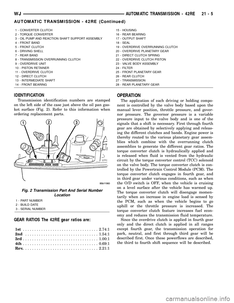
Transmission identification numbers are stamped
on the left side of the case just above the oil pan gas-
ket surface (Fig. 2). Refer to this information when
ordering replacement parts.
GEAR RATIOS The 42RE gear ratios are:
1st.................................2.74:1
2nd................................1.54:1
3rd.................................1.00:1
4th.................................0.69:1
Rev.................................2.21:1
OPERATION
The application of each driving or holding compo-
nent is controlled by the valve body based upon the
manual lever position, throttle pressure, and gover-
nor pressure. The governor pressure is a variable
pressure input to the valve body and is one of the
signals that a shift is necessary. First through fourth
gear are obtained by selectively applying and releas-
ing the different clutches and bands. Engine power is
thereby routed to the various planetary gear assem-
blies which combine with the overrunning clutch
assemblies to generate the different gear ratios. The
torque converter clutch is hydraulically applied and
is released when fluid is vented from the hydraulic
circuit by the torque converter control (TCC) solenoid
on the valve body. The torque converter clutch is con-
trolled by the Powertrain Control Module (PCM). The
torque converter clutch engages in fourth gear, and
in third gear under various conditions, such as when
the O/D switch is OFF, when the vehicle is cruising
on a level surface after the vehicle has warmed up.
The torque converter clutch will disengage momen-
tarily when an increase in engine load is sensed by
the PCM, such as when the vehicle begins to go
uphill or the throttle pressure is increased. The
torque converter clutch feature increases fuel econ-
omy and reduces the transmission fluid temperature.
Since the overdrive clutch is applied in fourth gear
only and the direct clutch is applied in all ranges
except fourth gear, the transmission operation for
park, neutral, and first through third gear will be
described first. Once these powerflows are described,
the third to fourth shift sequence will be described.
1 - CONVERTER CLUTCH 15 - HOUSING
2 - TORQUE CONVERTER 16 - REAR BEARING
3 - OIL PUMP AND REACTION SHAFT SUPPORT ASSEMBLY 17 - OUTPUT SHAFT
4 - FRONT BAND 18 - SEAL
5 - FRONT CLUTCH 19 - OVERDRIVE OVERRUNNING CLUTCH
6 - DRIVING SHELL 20 - OVERDRIVE PLANETARY GEAR
7 - REAR BAND 21 - DIRECT CLUTCH SPRING
8 - TRANSMISSION OVERRUNNING CLUTCH 22 - OVERDRIVE CLUTCH PISTON
9 - OVERDRIVE UNIT 23 - VALVE BODY ASSEMBLY
10 - PISTON RETAINER 24 - FILTER
11 - OVERDRIVE CLUTCH 25 - FRONT PLANETARY GEAR
12 - DIRECT CLUTCH 26 - REAR CLUTCH
13 - INTERMEDIATE SHAFT 27 - TRANSMISSION
14 - FRONT BEARING 28 - REAR PLANETARY GEAR
Fig. 2 Transmission Part And Serial Number
Location
1 - PART NUMBER
2 - BUILD DATE
3 - SERIAL NUMBER
WJAUTOMATIC TRANSMISSION - 42RE 21 - 5
AUTOMATIC TRANSMISSION - 42RE (Continued)
Page 1535 of 2199
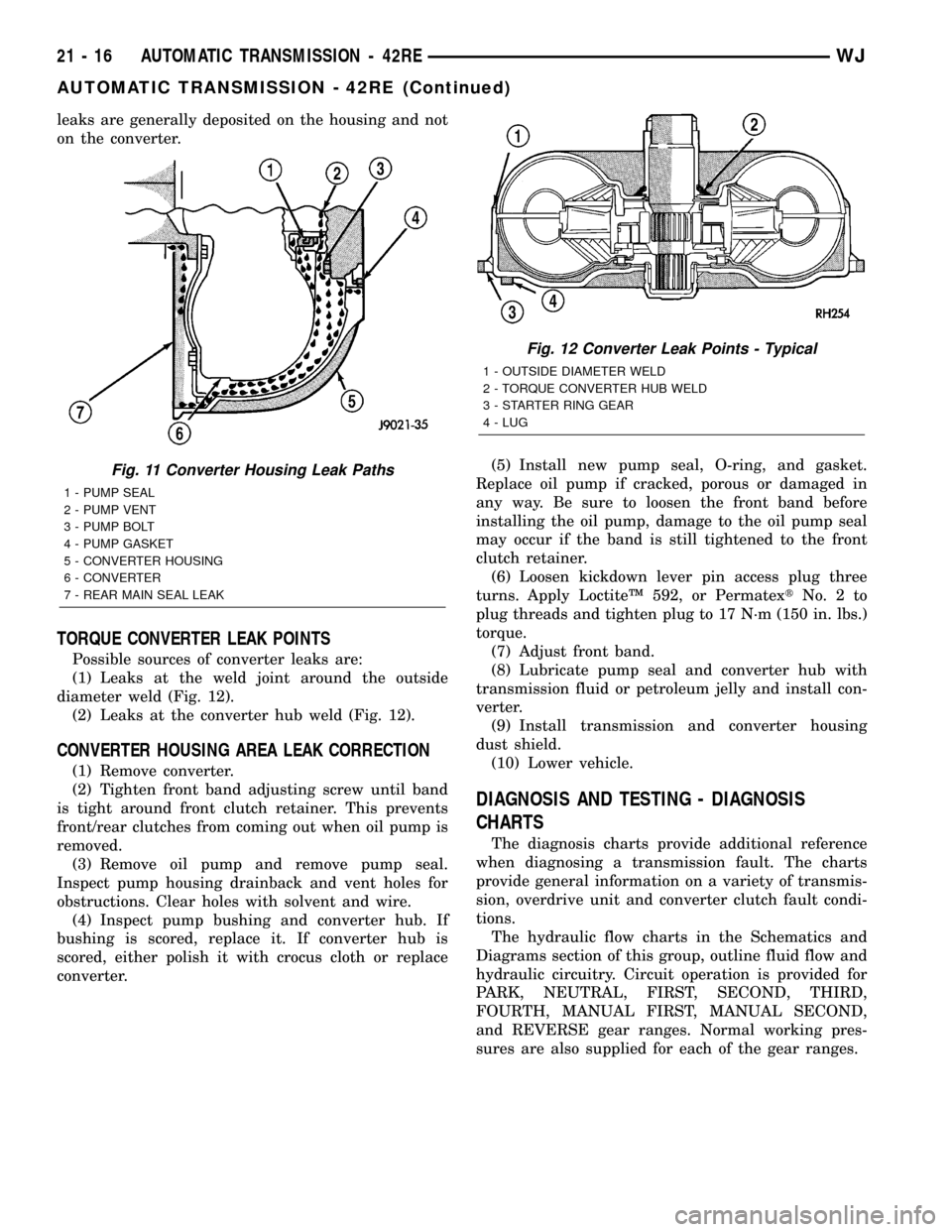
leaks are generally deposited on the housing and not
on the converter.
TORQUE CONVERTER LEAK POINTS
Possible sources of converter leaks are:
(1) Leaks at the weld joint around the outside
diameter weld (Fig. 12).
(2) Leaks at the converter hub weld (Fig. 12).
CONVERTER HOUSING AREA LEAK CORRECTION
(1) Remove converter.
(2) Tighten front band adjusting screw until band
is tight around front clutch retainer. This prevents
front/rear clutches from coming out when oil pump is
removed.
(3) Remove oil pump and remove pump seal.
Inspect pump housing drainback and vent holes for
obstructions. Clear holes with solvent and wire.
(4) Inspect pump bushing and converter hub. If
bushing is scored, replace it. If converter hub is
scored, either polish it with crocus cloth or replace
converter.(5) Install new pump seal, O-ring, and gasket.
Replace oil pump if cracked, porous or damaged in
any way. Be sure to loosen the front band before
installing the oil pump, damage to the oil pump seal
may occur if the band is still tightened to the front
clutch retainer.
(6) Loosen kickdown lever pin access plug three
turns. Apply LoctiteŸ 592, or PermatextNo.2to
plug threads and tighten plug to 17 N´m (150 in. lbs.)
torque.
(7) Adjust front band.
(8) Lubricate pump seal and converter hub with
transmission fluid or petroleum jelly and install con-
verter.
(9) Install transmission and converter housing
dust shield.
(10) Lower vehicle.
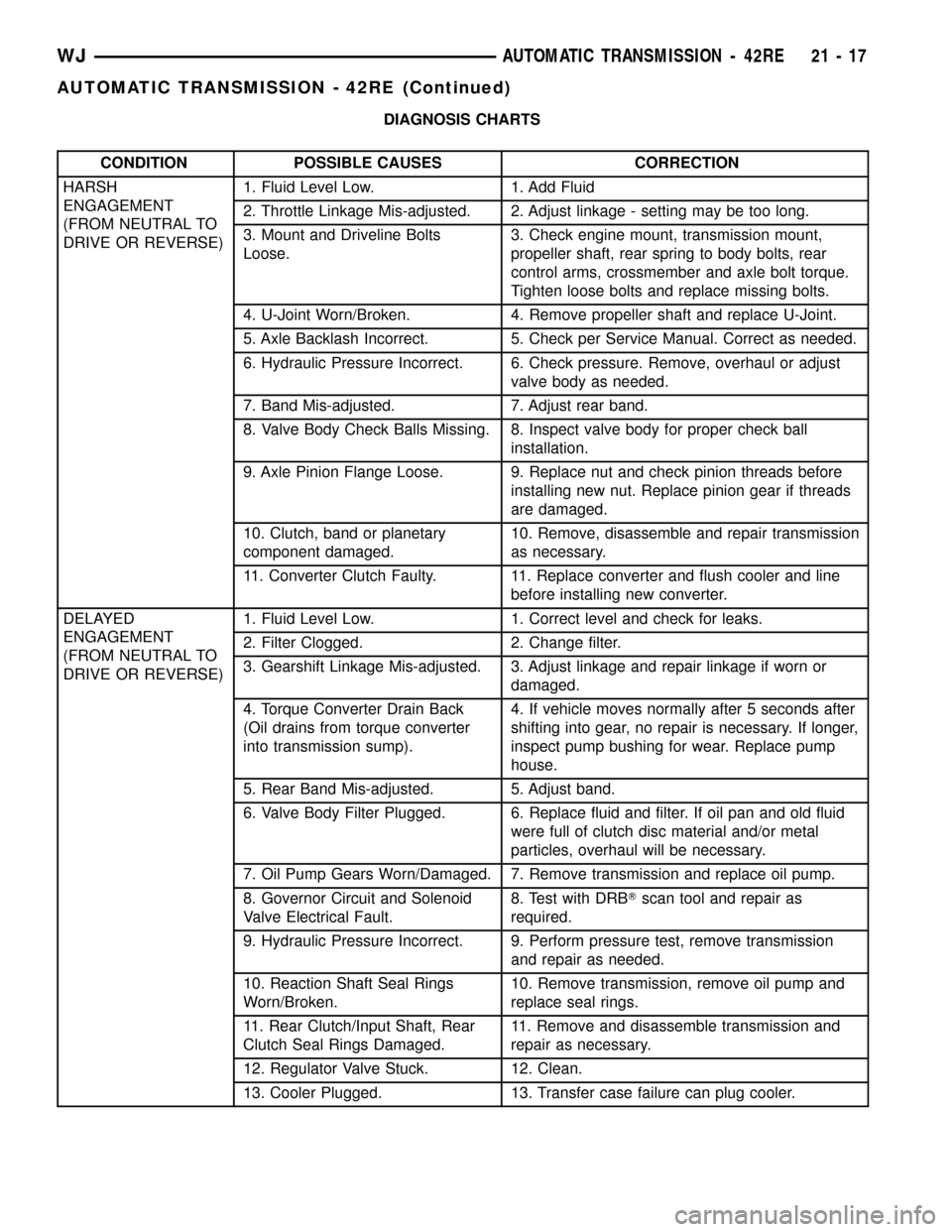
DIAGNOSIS AND TESTING - DIAGNOSIS
CHARTS
The diagnosis charts provide additional reference
when diagnosing a transmission fault. The charts
provide general information on a variety of transmis-
sion, overdrive unit and converter clutch fault condi-
tions.
The hydraulic flow charts in the Schematics and
Diagrams section of this group, outline fluid flow and
hydraulic circuitry. Circuit operation is provided for
PARK, NEUTRAL, FIRST, SECOND, THIRD,
FOURTH, MANUAL FIRST, MANUAL SECOND,
and REVERSE gear ranges. Normal working pres-
sures are also supplied for each of the gear ranges.
Fig. 11 Converter Housing Leak Paths
1 - PUMP SEAL
2 - PUMP VENT
3 - PUMP BOLT
4 - PUMP GASKET
5 - CONVERTER HOUSING
6 - CONVERTER
7 - REAR MAIN SEAL LEAK
Fig. 12 Converter Leak Points - Typical
1 - OUTSIDE DIAMETER WELD
2 - TORQUE CONVERTER HUB WELD
3 - STARTER RING GEAR
4 - LUG
21 - 16 AUTOMATIC TRANSMISSION - 42REWJ
AUTOMATIC TRANSMISSION - 42RE (Continued)
Page 1536 of 2199
DIAGNOSIS CHARTS
CONDITION POSSIBLE CAUSES CORRECTION
HARSH
ENGAGEMENT
(FROM NEUTRAL TO
DRIVE OR REVERSE)1. Fluid Level Low. 1. Add Fluid
2. Throttle Linkage Mis-adjusted. 2. Adjust linkage - setting may be too long.
3. Mount and Driveline Bolts
Loose.3. Check engine mount, transmission mount,
propeller shaft, rear spring to body bolts, rear
control arms, crossmember and axle bolt torque.
Tighten loose bolts and replace missing bolts.
4. U-Joint Worn/Broken. 4. Remove propeller shaft and replace U-Joint.
5. Axle Backlash Incorrect. 5. Check per Service Manual. Correct as needed.
6. Hydraulic Pressure Incorrect. 6. Check pressure. Remove, overhaul or adjust
valve body as needed.
7. Band Mis-adjusted. 7. Adjust rear band.
8. Valve Body Check Balls Missing. 8. Inspect valve body for proper check ball
installation.
9. Axle Pinion Flange Loose. 9. Replace nut and check pinion threads before
installing new nut. Replace pinion gear if threads
are damaged.
10. Clutch, band or planetary
component damaged.10. Remove, disassemble and repair transmission
as necessary.
11. Converter Clutch Faulty. 11. Replace converter and flush cooler and line
before installing new converter.
DELAYED
ENGAGEMENT
(FROM NEUTRAL TO
DRIVE OR REVERSE)1. Fluid Level Low. 1. Correct level and check for leaks.
2. Filter Clogged. 2. Change filter.
3. Gearshift Linkage Mis-adjusted. 3. Adjust linkage and repair linkage if worn or
damaged.
4. Torque Converter Drain Back
(Oil drains from torque converter
into transmission sump).4. If vehicle moves normally after 5 seconds after
shifting into gear, no repair is necessary. If longer,
inspect pump bushing for wear. Replace pump
house.
5. Rear Band Mis-adjusted. 5. Adjust band.
6. Valve Body Filter Plugged. 6. Replace fluid and filter. If oil pan and old fluid
were full of clutch disc material and/or metal
particles, overhaul will be necessary.
7. Oil Pump Gears Worn/Damaged. 7. Remove transmission and replace oil pump.
8. Governor Circuit and Solenoid
Valve Electrical Fault.8. Test with DRBTscan tool and repair as
required.
9. Hydraulic Pressure Incorrect. 9. Perform pressure test, remove transmission
and repair as needed.
10. Reaction Shaft Seal Rings
Worn/Broken.10. Remove transmission, remove oil pump and
replace seal rings.
11. Rear Clutch/Input Shaft, Rear
Clutch Seal Rings Damaged.11. Remove and disassemble transmission and
repair as necessary.
12. Regulator Valve Stuck. 12. Clean.
13. Cooler Plugged. 13. Transfer case failure can plug cooler.
WJAUTOMATIC TRANSMISSION - 42RE 21 - 17
AUTOMATIC TRANSMISSION - 42RE (Continued)
Page 1544 of 2199
CONDITION POSSIBLE CAUSES CORRECTION
NO START IN PARK
OR NEUTRAL1. Gearshift Linkage/Cable
Mis-adjusted.1. Adjust linkage/cable.
2. Neutral Sense Wire Open/Cut. 2. Check continuity with test lamp. Repair as
required.
3. Park/Neutral Switch, or
Transmission Range Sensor Faulty.3. Refer to service section for test and
replacement procedure.
4. Park/Neutral Switch, or
Transmission Range Sensor
Connection Faulty.4. Connectors spread open. Repair.
5. Valve Body Manual Lever
Assembly Bent/Worn/Broken.5. Inspect lever assembly and replace if damaged.
NO REVERSE (OR
SLIPS IN REVERSE)1. Direct Clutch Pack (front clutch)
Worn.1. Disassemble unit and rebuild clutch pack.
2. Rear Band Mis-adjusted. 2. Adjust band.
3. Front Clutch Malfunctioned/
Burned.3. Air-pressure test clutch operation. Remove and
rebuild if necessary.
4. Overdrive Thrust Bearing
Failure.4. Disassemble geartrain and replace bearings.
5. Direct Clutch Spring Collapsed/
Broken.5. Remove and disassemble unit. Check clutch
position and replace spring.
WJAUTOMATIC TRANSMISSION - 42RE 21 - 25
AUTOMATIC TRANSMISSION - 42RE (Continued)
Page 1545 of 2199
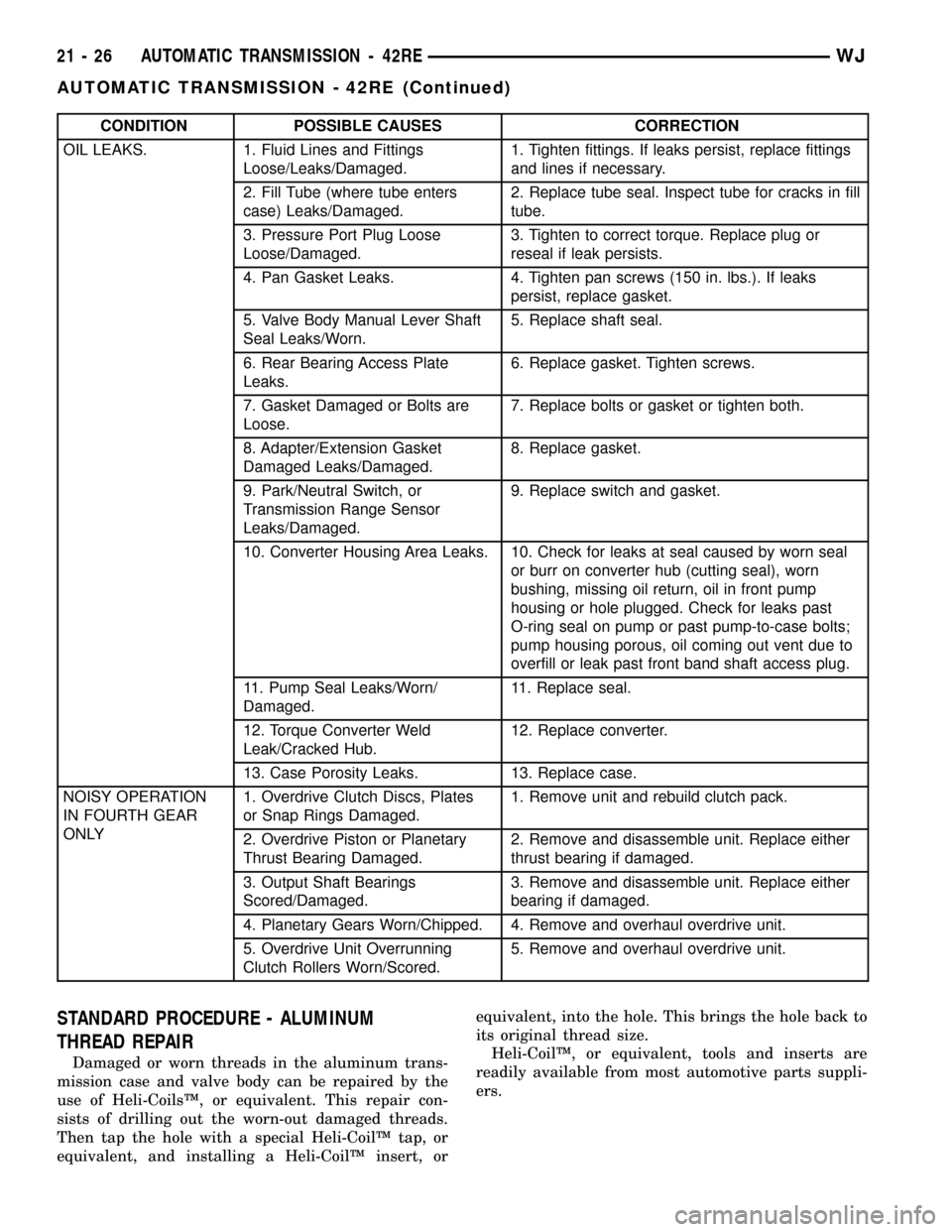
CONDITION POSSIBLE CAUSES CORRECTION
OIL LEAKS. 1. Fluid Lines and Fittings
Loose/Leaks/Damaged.1. Tighten fittings. If leaks persist, replace fittings
and lines if necessary.
2. Fill Tube (where tube enters
case) Leaks/Damaged.2. Replace tube seal. Inspect tube for cracks in fill
tube.
3. Pressure Port Plug Loose
Loose/Damaged.3. Tighten to correct torque. Replace plug or
reseal if leak persists.
4. Pan Gasket Leaks. 4. Tighten pan screws (150 in. lbs.). If leaks
persist, replace gasket.
5. Valve Body Manual Lever Shaft
Seal Leaks/Worn.5. Replace shaft seal.
6. Rear Bearing Access Plate
Leaks.6. Replace gasket. Tighten screws.
7. Gasket Damaged or Bolts are
Loose.7. Replace bolts or gasket or tighten both.
8. Adapter/Extension Gasket
Damaged Leaks/Damaged.8. Replace gasket.
9. Park/Neutral Switch, or
Transmission Range Sensor
Leaks/Damaged.9. Replace switch and gasket.
10. Converter Housing Area Leaks. 10. Check for leaks at seal caused by worn seal
or burr on converter hub (cutting seal), worn
bushing, missing oil return, oil in front pump
housing or hole plugged. Check for leaks past
O-ring seal on pump or past pump-to-case bolts;
pump housing porous, oil coming out vent due to
overfill or leak past front band shaft access plug.
11. Pump Seal Leaks/Worn/
Damaged.11. Replace seal.
12. Torque Converter Weld
Leak/Cracked Hub.12. Replace converter.
13. Case Porosity Leaks. 13. Replace case.
NOISY OPERATION
IN FOURTH GEAR
ONLY1. Overdrive Clutch Discs, Plates
or Snap Rings Damaged.1. Remove unit and rebuild clutch pack.
2. Overdrive Piston or Planetary
Thrust Bearing Damaged.2. Remove and disassemble unit. Replace either
thrust bearing if damaged.
3. Output Shaft Bearings
Scored/Damaged.3. Remove and disassemble unit. Replace either
bearing if damaged.
4. Planetary Gears Worn/Chipped. 4. Remove and overhaul overdrive unit.
5. Overdrive Unit Overrunning
Clutch Rollers Worn/Scored.5. Remove and overhaul overdrive unit.
STANDARD PROCEDURE - ALUMINUM
THREAD REPAIR
Damaged or worn threads in the aluminum trans-
mission case and valve body can be repaired by the
use of Heli-CoilsŸ, or equivalent. This repair con-
sists of drilling out the worn-out damaged threads.
Then tap the hole with a special Heli-CoilŸ tap, or
equivalent, and installing a Heli-CoilŸ insert, orequivalent, into the hole. This brings the hole back to
its original thread size.
Heli-CoilŸ, or equivalent, tools and inserts are
readily available from most automotive parts suppli-
ers.
21 - 26 AUTOMATIC TRANSMISSION - 42REWJ
AUTOMATIC TRANSMISSION - 42RE (Continued)
Page 1546 of 2199

REMOVAL
The overdrive unit can be removed and serviced
separately. It is not necessary to remove the entire
transmission assembly to perform overdrive unit
repairs.
If only the overdrive unit requires service, refer to
Overdrive Removal for proper procedures.
CAUTION: The transmission and torque converter
must be removed as an assembly to avoid compo-
nent damage. The converter driveplate, pump bush-
ing, or oil seal can be damaged if the converter is
left attached to the driveplate during removal. Be
sure to remove the transmission and converter as
an assembly.
(1) Disconnect battery negative cable.
(2) Disconnect and lower or remove necessary
exhaust components.
(3) Disconnect fluid cooler lines at transmission.
(4) Remove starter motor. (Refer to 8 - ELECTRI-
CAL/STARTING/STARTER MOTOR - REMOVAL)
(5) Disconnect and remove crankshaft position sen-
sor. (Refer to 14 - FUEL SYSTEM/FUEL INJEC-
TION/CRANKSHAFT POSITION SENSOR -
REMOVAL) Retain sensor attaching bolts.
CAUTION: The crankshaft position sensor will be
damaged if the transmission is removed, or
installed, while the sensor is still bolted to the
engine block, or transmission (4.0L only). To avoid
damage, be sure to remove the sensor before
removing the transmission.
(6) Remove the bolts holding the bell housing
brace to the transmission.
(7) Remove nut holding the bell housing brace to
the engine to transmission bending brace.
(8) Remove the bell housing brace from the trans-
mission (Fig. 13).
(9) Remove the bolt holding the torque converter
cover to the transmission.
(10) Remove the torque converter cover from the
transmission.
(11) If transmission is being removed for overhaul,
remove transmission oil pan, drain fluid and reinstall
pan.
(12) Remove fill tube bracket bolts and pull tube
out of transmission. Retain fill tube seal. On4x4
models, it will also be necessary to remove bolt
attaching transfer case vent tube to converter hous-
ing.
(13) Rotate crankshaft in clockwise direction until
converter bolts are accessible. Then remove bolts one
at a time. Rotate crankshaft with socket wrench on
dampener bolt.(14) Mark propeller shaft and axle yokes for
assembly alignment. Then disconnect and remove
propeller shaft. On4x4models, remove both propel-
ler shafts.
(15) Disconnect wires from park/neutral position
switch and transmission solenoid.
(16) Disconnect gearshift cable from transmission
manual valve lever (Fig. 14).
Fig. 13 Bell Housing Brace and Converter Cover
1 - Transmission
2 - Torque Converter Cover
3 - Bellhousing Brace
Fig. 14 Transmission Shift Cable
1 - SHIFT CABLE
2 - MANUAL LEVER
3 - MANUAL LEVER
WJAUTOMATIC TRANSMISSION - 42RE 21 - 27
AUTOMATIC TRANSMISSION - 42RE (Continued)