2003 JEEP GRAND CHEROKEE Panel
[x] Cancel search: PanelPage 646 of 2199

along the left roof side rail to the rear of the vehicle.
At the rear of the vehicle, the headliner hose is
routed above the headliner and along the upper lift-
gate opening panel toward the right side of the vehi-
cle. The headliner hose then passes through a hole
with a rubber grommet in the upper liftgate opening
panel and through another hole with a rubber grom-
met into the upper inner liftgate panel to the rear
washer nozzle.
Washer hose is available for service only as roll
stock, which must then be cut to length. The head-
liner washer hose is integral to the headliner unit
and, if faulty or damaged, the headliner unit must be
replaced. The molded plastic washer hose fittings
cannot be repaired. If these fittings are faulty or
damaged, they must be replaced.
OPERATION
Washer fluid in the washer reservoir is pressurized
and fed by the rear washer pump/motor through the
rear washer system plumbing and fittings to the rear
washer nozzle on the liftgate outer panel above the
liftgate glass. Whenever routing the washer hose or a
wire harness containing a washer hose, it must be
routed away from hot, sharp, or moving parts; and,
sharp bends that might pinch the hose must be
avoided.
REAR WASHER NOZZLE
DESCRIPTION
The rear washer nozzle is a fluidic type unit that
includes an integral check valve (Fig. 3). The nozzle
is constructed of molded plastic and has a rubber
seal and integral snap features on the back of it. The
nozzle is secured by a snap fit in a dedicated mount-
ing hole in the liftgate outer panel above the liftgate
flip-up glass. Within the rear nozzle body, a small
check ball is held against an integral valve seat at
the inlet end of the nozzle by a small coiled spring.
The rear washer nozzle and check valve unit cannot
be adjusted or repaired. If faulty or damaged, the
entire nozzle and check valve unit must be replaced.
OPERATION
The rear washer nozzle is designed to dispense
washer fluid into the wiper pattern area on the out-
side of the liftgate glass. Pressurized washer fluid is
fed to the nozzle from the washer reservoir by the
rear washer pump/motor through a single hose,
which is attached to a barbed nipple on the back of
the rear washer nozzle. The rear washer nozzle
incorporates a fluidic design, which causes the nozzle
to emit the pressurized washer fluid as an oscillating
stream to more effectively cover a larger area of the
glass area to be cleaned. The integral rear nozzle
check valve prevents washer fluid from draining out
of the rear washer supply hoses back to the washer
reservoir. This drain-back would result in a lengthy
delay from when the rear washer switch is actuated
until washer fluid was dispensed through the rear
washer nozzle, because the rear washer pump would
have to refill the rear washer plumbing from the res-
ervoir to the nozzle. The check valve also prevents
washer fluid from siphoning through the rear washer
nozzle after the rear washer system is turned Off.
When the rear washer pump pressurizes and pumps
washer fluid from the reservoir through the rear
washer plumbing, the fluid pressure overrides the
spring pressure applied to the check ball within the
valve and unseats the check ball, allowing washer
fluid to flow to the rear washer nozzle. When the
rear washer pump stops operating, spring pressure
seats the check ball in the valve and fluid flow in
either direction within the rear washer plumbing is
prevented.
REMOVAL
The check valve for the rear washer nozzle is inte-
gral to the nozzle.
(1) Using a trim stick or another suitable wide
flat-bladed tool, gently pry at the sides of the rear
washer nozzle to release the snap features that
secure it in the mounting hole of the liftgate outer
panel.
Fig. 3 Rear Washer Nozzle
1 - HEADLINER WASHER HOSE
2 - ROOF PANEL
3 - REAR WASHER NOZZLE
4 - LIFTGATE
WJREAR WIPERS/WASHERS 8R - 39
REAR WASHER HOSES/TUBES (Continued)
Page 647 of 2199

(2) Pull the rear washer nozzle out from the lift-
gate outer panel far enough to access the washer
supply hose (Fig. 4).
(3) Disconnect the washer supply hose from the
barbed nipple of the rear washer nozzle.
(4) Remove the rear washer nozzle from the lift-
gate.
INSTALLATION
(1) Position the rear washer nozzle to the liftgate
(Fig. 4).
(2) Reconnect the washer supply hose to the
barbed nipple of the rear washer nozzle.
(3) Insert the rear washer nozzle supply hose and
nipple into the mounting hole in the liftgate outer
panel.
(4) Using hand pressure, push firmly and evenly
on the rear washer nozzle until the snap features
lock into place on the inside of the liftgate outer
panel mounting hole.
REAR WASHER PUMP/MOTOR
DESCRIPTION
The rear washer pump/motor unit is located on the
outboard side and near the rear of the washer reser-
voir, between the left front inner and outer fender
panels (Fig. 5). A small permanently lubricated and
sealed electric motor is coupled to the rotor-type
washer pump. A seal flange with a large barbed inlet
nipple on the pump housing passes through a rubber
grommet seal installed in one of two dedicatedmounting holes near the bottom of the washer reser-
voir. The rear washer pump/motor unit is always
mounted in the higher pump mounting hole of the
reservoir. A smaller barbed outlet nipple on the pump
housing connects the unit to the rear washer hose.
The washer pump/motor unit is retained on the res-
ervoir by the interference fit between the barbed
pump inlet nipple and the grommet seal, which is a
light press fit. An integral electrical connector recep-
tacle is located on the top of the motor housing. The
rear washer pump/motor unit cannot be repaired. If
faulty or damaged, the entire washer pump/motor
unit must be replaced.
OPERATION
The rear washer pump/motor unit is connected to
the vehicle electrical system through a single take
out and two-cavity connector of the left headlamp
and dash wire harness. The washer pump/motor is
grounded at all times through a take out of the left
headlamp and dash wire harness with a single eyelet
terminal connector that is secured under a ground
screw to the top of the left inner fender shield in the
engine compartment. The rear washer pump/motor
receives battery current on a fused ignition switch
output (run-acc) circuit through the closed contacts of
the momentary rear washer switch within the right
multi-function switch only when the switch control
stalk is pushed towards the instrument panel.
Washer fluid is gravity-fed from the washer reservoir
to the inlet side of the washer pump. When the pump
motor is energized, the rotor-type pump pressurizes
Fig. 4 Rear Washer Nozzle Remove/Install
1 - HEADLINER WASHER HOSE
2 - ROOF PANEL
3 - REAR WASHER NOZZLE
4 - LIFTGATE
Fig. 5 Washer Pumps (Viewed from Bottom of
Reservoir)
1 - REAR WASHER PUMP/MOTOR
2 - FRONT WASHER PUMP/MOTOR
3 - WASHER FLUID LEVEL SWITCH
8R - 40 REAR WIPERS/WASHERSWJ
REAR WASHER NOZZLE (Continued)
Page 648 of 2199
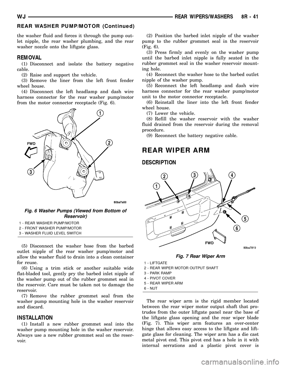
the washer fluid and forces it through the pump out-
let nipple, the rear washer plumbing, and the rear
washer nozzle onto the liftgate glass.
REMOVAL
(1) Disconnect and isolate the battery negative
cable.
(2) Raise and support the vehicle.
(3) Remove the liner from the left front fender
wheel house.
(4) Disconnect the left headlamp and dash wire
harness connector for the rear washer pump/motor
from the motor connector receptacle (Fig. 6).
(5) Disconnect the washer hose from the barbed
outlet nipple of the rear washer pump/motor and
allow the washer fluid to drain into a clean container
for reuse.
(6) Using a trim stick or another suitable wide
flat-bladed tool, gently pry the barbed inlet nipple of
the washer pump out of the rubber grommet seal in
the reservoir. Care must be taken not to damage the
reservoir.
(7) Remove the rubber grommet seal from the
washer pump mounting hole in the washer reservoir
and discard.
INSTALLATION
(1) Install a new rubber grommet seal into the
washer pump mounting hole in the washer reservoir.
Always use a new rubber grommet seal on the reser-
voir.(2) Position the barbed inlet nipple of the washer
pump to the rubber grommet seal in the reservoir
(Fig. 6).
(3) Press firmly and evenly on the washer pump
until the barbed inlet nipple is fully seated in the
rubber grommet seal in the washer reservoir mount-
ing hole.
(4) Reconnect the washer hose to the barbed outlet
nipple of the washer pump.
(5) Reconnect the left headlamp and dash wire
harness connector for the rear washer pump/motor
unit to the motor connector receptacle.
(6) Reinstall the liner into the left front fender
wheel house.
(7) Lower the vehicle.
(8) Refill the washer reservoir with the washer
fluid drained from the reservoir during the removal
procedure.
(9) Reconnect the battery negative cable.
REAR WIPER ARM
DESCRIPTION
The rear wiper arm is the rigid member located
between the rear wiper motor output shaft that pro-
trudes from the outer liftgate panel near the base of
the liftgate glass opening and the rear wiper blade
(Fig. 7). This wiper arm features an over-center
hinge that allows easy access to the liftgate and lift-
gate glass for cleaning. The wiper arm has a die cast
metal pivot end. This pivot end has a hole in it with
internal serrations and a plastic pivot cover is
Fig. 6 Washer Pumps (Viewed from Bottom of
Reservoir)
1 - REAR WASHER PUMP/MOTOR
2 - FRONT WASHER PUMP/MOTOR
3 - WASHER FLUID LEVEL SWITCH
Fig. 7 Rear Wiper Arm
1 - LIFTGATE
2 - REAR WIPER MOTOR OUTPUT SHAFT
3 - PARK RAMP
4 - PIVOT COVER
5 - REAR WIPER ARM
6 - NUT
WJREAR WIPERS/WASHERS 8R - 41
REAR WASHER PUMP/MOTOR (Continued)
Page 649 of 2199
secured loosely to and pivots on the wiper arm hinge
pin to conceal the wiper arm retaining nut. The wide
end of a tapered, stamped steel channel is secured
with a hinge pin to the pivot end of the wiper arm.
One end of a long, rigid, stamped steel strap, with a
small hole near its pivot end, is riveted and crimped
within the narrow end of the stamped steel channel.
The tip of the wiper blade end of this strap is bent
back under itself to form a small hook. Concealed
within the stamped steel channel, one end of a long
spring is engaged with a wire hook on the underside
of the die cast pivot end, while the other end of the
spring is hooked through the small hole in the steel
strap. A molded plastic wiper arm support is snapped
onto the wiper arm strap where it exits the channel.
The entire wiper arm has a satin black finish applied
to all of its visible surfaces.
A wiper arm cannot be adjusted or repaired. If
damaged or faulty, the entire wiper arm unit must be
replaced.
OPERATION
The rear wiper arm is designed to mechanically
transmit the motion from the rear wiper motor out-
put shaft to the rear wiper blade. The wiper arm
must be properly indexed to the motor output shaft
in order to maintain the proper wiper blade travel on
the glass. The wiper arm support is designed to lift
and support the rear wiper arm and blade off of the
glass when the rear wiper blade is parked. This sup-
port and the park ramp on the liftgate outer panel
below the glass also provide an alignment reference
to ensure accurate rear wiper arm and blade instal-
lation. The hole with internal serrations in the wiper
arm pivot end interlocks with the serrations on the
outer circumference of the motor output shaft, allow-
ing positive engagement and finite adjustment of this
connection. A hex nut secures the wiper arm pivot
end to the threads on the motor output shaft and the
pivot cover hinges and snaps over this connection for
a neat appearance. The spring-loaded wiper arm
hinge controls the down-force applied through the tip
of the wiper arm to the wiper blade on the glass. The
hook formation on the tip of the wiper arm provides
a cradle for securing and latching the wiper blade
pivot block to the wiper arm.
REMOVAL
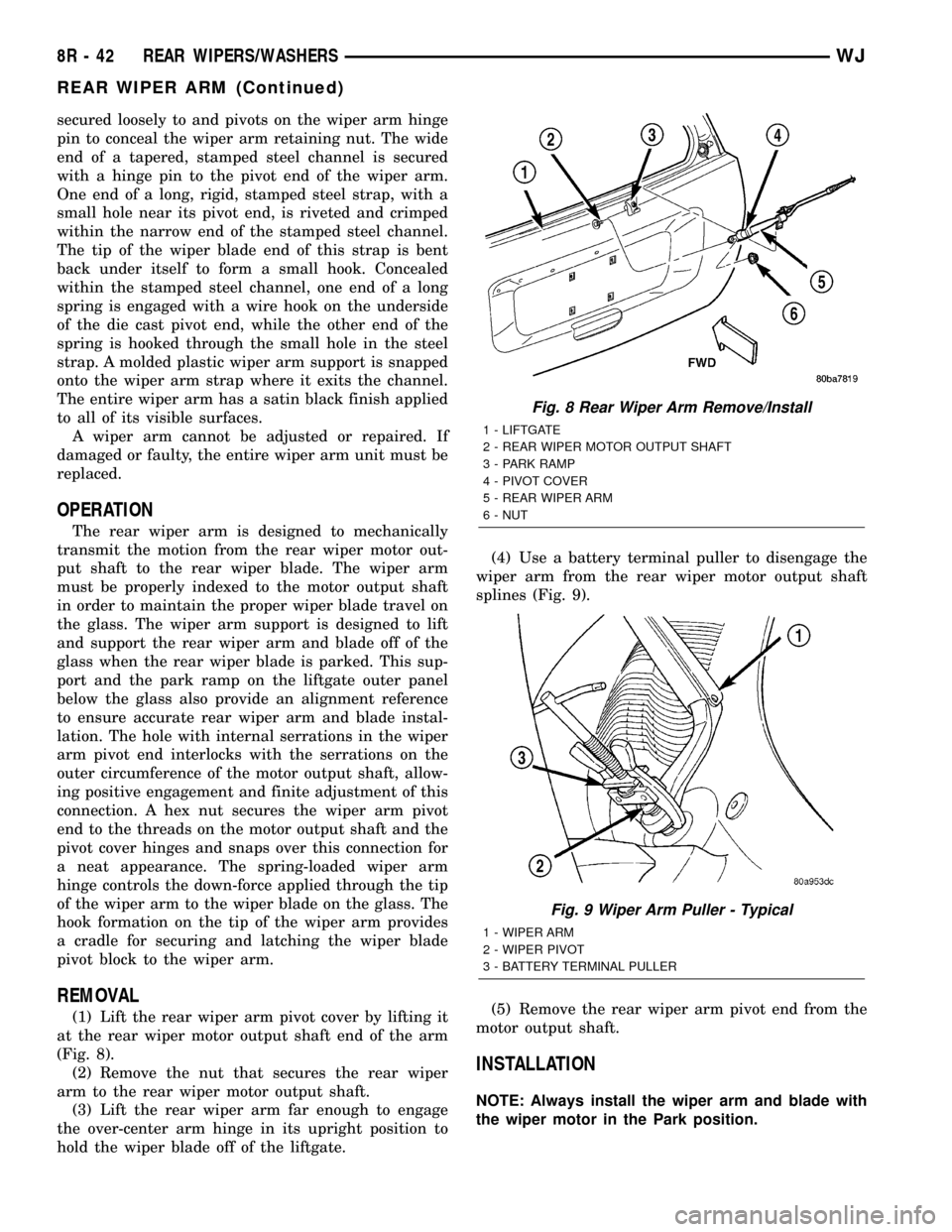
(1) Lift the rear wiper arm pivot cover by lifting it
at the rear wiper motor output shaft end of the arm
(Fig. 8).
(2) Remove the nut that secures the rear wiper
arm to the rear wiper motor output shaft.
(3) Lift the rear wiper arm far enough to engage
the over-center arm hinge in its upright position to
hold the wiper blade off of the liftgate.(4) Use a battery terminal puller to disengage the
wiper arm from the rear wiper motor output shaft
splines (Fig. 9).
(5) Remove the rear wiper arm pivot end from the
motor output shaft.
INSTALLATION
NOTE: Always install the wiper arm and blade with
the wiper motor in the Park position.
Fig. 8 Rear Wiper Arm Remove/Install
1 - LIFTGATE
2 - REAR WIPER MOTOR OUTPUT SHAFT
3 - PARK RAMP
4 - PIVOT COVER
5 - REAR WIPER ARM
6 - NUT
Fig. 9 Wiper Arm Puller - Typical
1 - WIPER ARM
2 - WIPER PIVOT
3 - BATTERY TERMINAL PULLER
8R - 42 REAR WIPERS/WASHERSWJ
REAR WIPER ARM (Continued)
Page 651 of 2199
REMOVAL
NOTE: The notched retainer end of the wiper ele-
ment should always be oriented towards the end of
the wiper blade that is nearest to the wiper motor
output shaft.
(1) Disengage the rear wiper arm support from the
rubber rear wiper arm park ramp on the right side of
the liftgate just below the liftgate glass.
(2) Lift the rear wiper arm to engage the arm
hinge in its over-center position with the wiper blade
and element off of the liftgate and the glass.
(3) To remove the wiper blade from the wiper arm,
push the pivot block latch release tab under the tip
of the arm and slide the blade away from the tip
towards the pivot end of the arm far enough to dis-
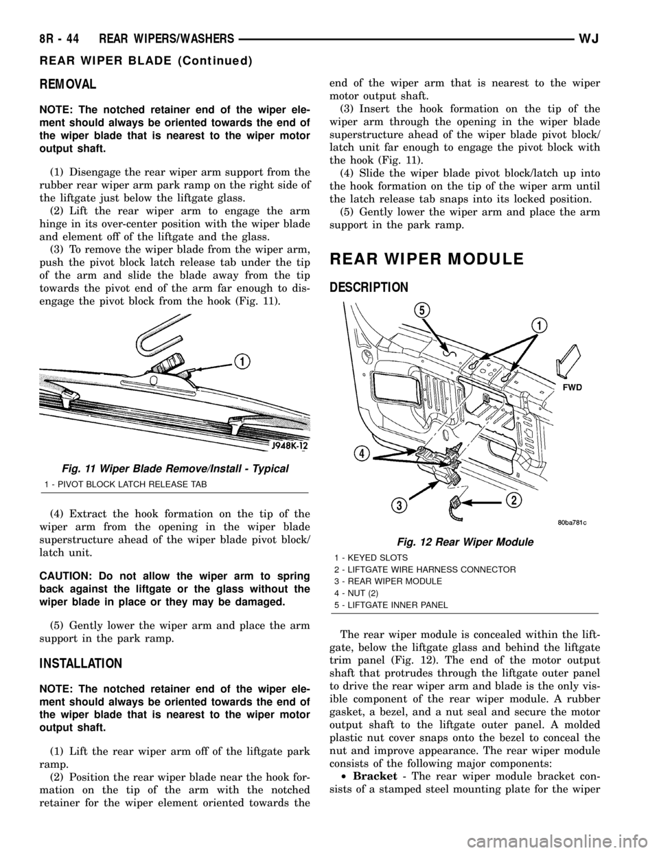
engage the pivot block from the hook (Fig. 11).
(4) Extract the hook formation on the tip of the
wiper arm from the opening in the wiper blade
superstructure ahead of the wiper blade pivot block/
latch unit.
CAUTION: Do not allow the wiper arm to spring
back against the liftgate or the glass without the
wiper blade in place or they may be damaged.
(5) Gently lower the wiper arm and place the arm
support in the park ramp.
INSTALLATION
NOTE: The notched retainer end of the wiper ele-
ment should always be oriented towards the end of
the wiper blade that is nearest to the wiper motor
output shaft.
(1) Lift the rear wiper arm off of the liftgate park
ramp.
(2) Position the rear wiper blade near the hook for-
mation on the tip of the arm with the notched
retainer for the wiper element oriented towards theend of the wiper arm that is nearest to the wiper
motor output shaft.
(3) Insert the hook formation on the tip of the
wiper arm through the opening in the wiper blade
superstructure ahead of the wiper blade pivot block/
latch unit far enough to engage the pivot block with
the hook (Fig. 11).
(4) Slide the wiper blade pivot block/latch up into
the hook formation on the tip of the wiper arm until
the latch release tab snaps into its locked position.
(5) Gently lower the wiper arm and place the arm
support in the park ramp.
REAR WIPER MODULE
DESCRIPTION
The rear wiper module is concealed within the lift-
gate, below the liftgate glass and behind the liftgate
trim panel (Fig. 12). The end of the motor output
shaft that protrudes through the liftgate outer panel
to drive the rear wiper arm and blade is the only vis-
ible component of the rear wiper module. A rubber
gasket, a bezel, and a nut seal and secure the motor
output shaft to the liftgate outer panel. A molded
plastic nut cover snaps onto the bezel to conceal the
nut and improve appearance. The rear wiper module
consists of the following major components:
²Bracket- The rear wiper module bracket con-
sists of a stamped steel mounting plate for the wiper
Fig. 11 Wiper Blade Remove/Install - Typical
1 - PIVOT BLOCK LATCH RELEASE TAB
Fig. 12 Rear Wiper Module
1 - KEYED SLOTS
2 - LIFTGATE WIRE HARNESS CONNECTOR
3 - REAR WIPER MODULE
4 - NUT (2)
5 - LIFTGATE INNER PANEL
8R - 44 REAR WIPERS/WASHERSWJ
REAR WIPER BLADE (Continued)
Page 652 of 2199
motor that is secured with screws to the wiper motor
and to the liftgate inner panel.
²Electronic Controls- The rear wiper module
electronic controls include the rear wiper system
electronic logic and rear wiper motor electronic con-
trols. The electronic controls for the motor include an
electronic speed control that speeds the wiper blade
near the center of the glass, but slows the wiper
blade during directional reversals at each end of the
wipe pattern and during wiper blade off-the-glass
parking for quieter operation.
²Motor- The permanent magnet rear wiper
motor is secured with screws to the rear wiper mod-
ule bracket. The wiper motor includes an integral
transmission, and the motor output shaft.
The rear wiper module cannot be adjusted or
repaired. If any component of the module is faulty or
damaged, the entire rear wiper module unit must be
replaced. The motor output shaft gasket, bezel, nut,
and nut cover are available for service replacement.
OPERATION
The rear wiper module receives non-switched bat-
tery current through a fuse in the Junction Block
(JB) and is grounded at all times. The rear wiper
module operation is controlled by the vehicle operator
through battery current signal inputs received by the
rear wiper module electronic controls from the right
multi-function switch on the steering column. The
module also receives an external control input from
the liftgate flip-up glass ajar switch circuit. The rear
wiper module electronic control logic uses these
inputs, its internal inputs, and its programming to
provide continuous wipe, delay wipe, wipe-after-wash
and off-the-glass wiper blade parking. The wiper
blade cycling is controlled by the rear wiper module
electronic controls, which control current flow to the
wiper motor brushes. The wiper motor transmission
converts the rotary output of the wiper motor to the
back and forth wiping motion of the rear wiper arm
and blade on the liftgate glass.
REMOVAL
(1) Disconnect and isolate the battery negative
cable.
(2) Remove the rear wiper arm from the rear
wiper motor output shaft. (Refer to 8 - ELECTRI-
CAL/REAR WIPERS/WASHERS/REAR WIPER ARM
- REMOVAL).
(3) Use a door trim panel removal tool to gently
pry at the base of the nut cover where it meets the
wiper motor output shaft bezel and gasket on the
outer liftgate panel until it unsnaps from the bezel
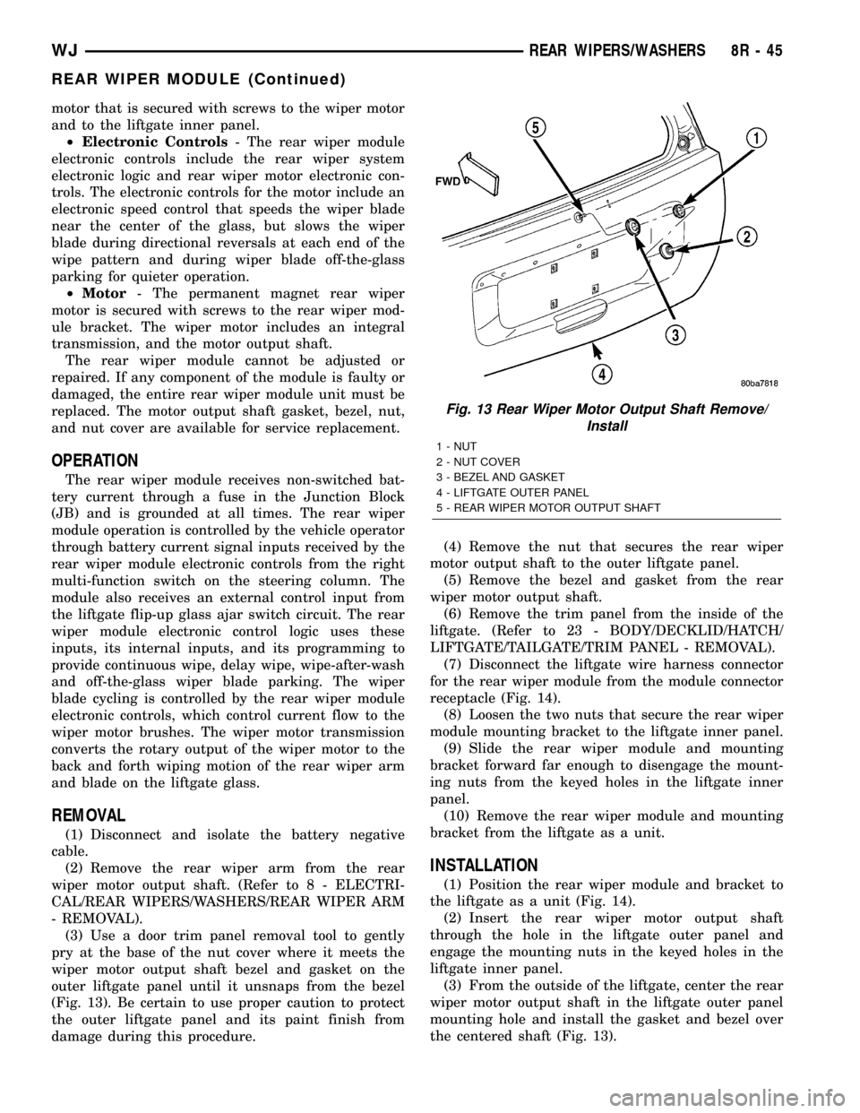
(Fig. 13). Be certain to use proper caution to protect
the outer liftgate panel and its paint finish from
damage during this procedure.(4) Remove the nut that secures the rear wiper
motor output shaft to the outer liftgate panel.
(5) Remove the bezel and gasket from the rear
wiper motor output shaft.
(6) Remove the trim panel from the inside of the
liftgate. (Refer to 23 - BODY/DECKLID/HATCH/
LIFTGATE/TAILGATE/TRIM PANEL - REMOVAL).
(7) Disconnect the liftgate wire harness connector
for the rear wiper module from the module connector
receptacle (Fig. 14).
(8) Loosen the two nuts that secure the rear wiper
module mounting bracket to the liftgate inner panel.
(9) Slide the rear wiper module and mounting
bracket forward far enough to disengage the mount-
ing nuts from the keyed holes in the liftgate inner
panel.
(10) Remove the rear wiper module and mounting
bracket from the liftgate as a unit.
INSTALLATION
(1) Position the rear wiper module and bracket to
the liftgate as a unit (Fig. 14).
(2) Insert the rear wiper motor output shaft
through the hole in the liftgate outer panel and
engage the mounting nuts in the keyed holes in the
liftgate inner panel.
(3) From the outside of the liftgate, center the rear
wiper motor output shaft in the liftgate outer panel
mounting hole and install the gasket and bezel over
the centered shaft (Fig. 13).
Fig. 13 Rear Wiper Motor Output Shaft Remove/
Install
1 - NUT
2 - NUT COVER
3 - BEZEL AND GASKET
4 - LIFTGATE OUTER PANEL
5 - REAR WIPER MOTOR OUTPUT SHAFT
WJREAR WIPERS/WASHERS 8R - 45
REAR WIPER MODULE (Continued)
Page 653 of 2199
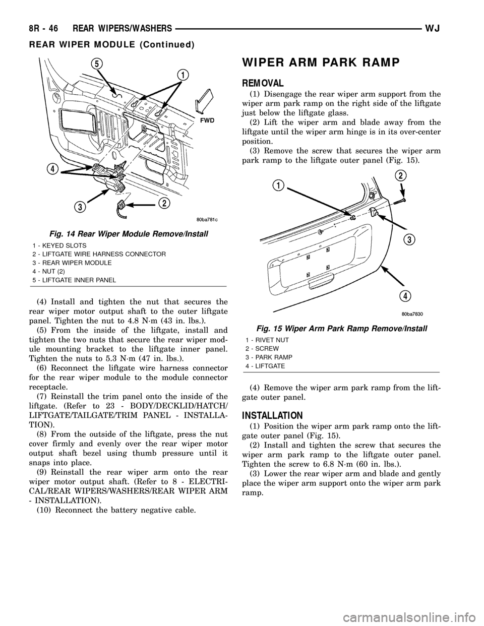
(4) Install and tighten the nut that secures the
rear wiper motor output shaft to the outer liftgate
panel. Tighten the nut to 4.8 N´m (43 in. lbs.).
(5) From the inside of the liftgate, install and
tighten the two nuts that secure the rear wiper mod-
ule mounting bracket to the liftgate inner panel.
Tighten the nuts to 5.3 N´m (47 in. lbs.).
(6) Reconnect the liftgate wire harness connector
for the rear wiper module to the module connector
receptacle.
(7) Reinstall the trim panel onto the inside of the
liftgate. (Refer to 23 - BODY/DECKLID/HATCH/
LIFTGATE/TAILGATE/TRIM PANEL - INSTALLA-
TION).
(8) From the outside of the liftgate, press the nut
cover firmly and evenly over the rear wiper motor
output shaft bezel using thumb pressure until it
snaps into place.
(9) Reinstall the rear wiper arm onto the rear
wiper motor output shaft. (Refer to 8 - ELECTRI-
CAL/REAR WIPERS/WASHERS/REAR WIPER ARM
- INSTALLATION).
(10) Reconnect the battery negative cable.
WIPER ARM PARK RAMP
REMOVAL
(1) Disengage the rear wiper arm support from the
wiper arm park ramp on the right side of the liftgate
just below the liftgate glass.
(2) Lift the wiper arm and blade away from the
liftgate until the wiper arm hinge is in its over-center
position.
(3) Remove the screw that secures the wiper arm
park ramp to the liftgate outer panel (Fig. 15).
(4) Remove the wiper arm park ramp from the lift-
gate outer panel.
INSTALLATION
(1) Position the wiper arm park ramp onto the lift-
gate outer panel (Fig. 15).
(2) Install and tighten the screw that secures the
wiper arm park ramp to the liftgate outer panel.
Tighten the screw to 6.8 N´m (60 in. lbs.).
(3) Lower the rear wiper arm and blade and gently
place the wiper arm support onto the wiper arm park
ramp.
Fig. 14 Rear Wiper Module Remove/Install
1 - KEYED SLOTS
2 - LIFTGATE WIRE HARNESS CONNECTOR
3 - REAR WIPER MODULE
4 - NUT (2)
5 - LIFTGATE INNER PANEL
Fig. 15 Wiper Arm Park Ramp Remove/Install
1 - RIVET NUT
2 - SCREW
3 - PARK RAMP
4 - LIFTGATE
8R - 46 REAR WIPERS/WASHERSWJ
REAR WIPER MODULE (Continued)
Page 662 of 2199

DESCRIPTION - CONNECTOR, GROUND AND
SPLICE INFORMATION
CAUTION: Not all connectors are serviced. Some
connectors are serviced only with a harness. A typ-
ical example might be the Supplemental Restraint
System connectors. Always check parts availability
before attempting a repair.
IDENTIFICATION
In-line connectors are identified by a number, as
follows:
²In-line connectors located in the engine compart-
ment are C100 series numbers
²In-line connectors located in the Instrument
Panel area are C200 series numbers.
²In-line connectors located in the body are C300
series numbers.
²Jumper harness connectors are C400 series
numbers.
²Grounds and ground connectors are identified
with a ªGº and follow the same series numbering as
the in-line connectors.
²Splices are identified with an ªSº and follow the
same series numbering as the in-line connectors.
²Component connectors are identified by the com-
ponent name instead of a number. Multiple connec-
tors on a component use a C1, C2, etc. identifier.
LOCATIONS
Section 8W-91 contains connector/ground/splice
location illustrations. The illustrations contain the
connector name (or number)/ground number/splice
number and component identification. Connector/
ground/splice location charts in section 8W-91 refer-
ence the figure numbers of the illustrations.
The abbreviation T/O is used in the component
location section to indicate a point in which the wir-
ing harness branches out to a component. The abbre-
viation N/S means Not Shown in the illustrations
WARNING
WARNINGS - GENERAL
WARNINGSprovide information to prevent per-
sonal injury and vehicle damage. Below is a list of
general warnings that should be followed any time a
vehicle is being serviced.
WARNING: ALWAYS WEAR SAFETY GLASSES FOR
EYE PROTECTION.
WARNING: USE SAFETY STANDS ANYTIME A PRO-
CEDURE REQUIRES BEING UNDER A VEHICLE.WARNING: BE SURE THAT THE IGNITION SWITCH
ALWAYS IS IN THE OFF POSITION, UNLESS THE
PROCEDURE REQUIRES IT TO BE ON.
WARNING: SET THE PARKING BRAKE WHEN
WORKING ON ANY VEHICLE. AN AUTOMATIC
TRANSMISSION SHOULD BE IN PARK. A MANUAL
TRANSMISSION SHOULD BE IN NEUTRAL.
WARNING: OPERATE THE ENGINE ONLY IN A
WELL-VENTILATED AREA.
WARNING: KEEP AWAY FROM MOVING PARTS
WHEN THE ENGINE IS RUNNING, ESPECIALLY THE
FAN AND BELTS.
WARNING: TO PREVENT SERIOUS BURNS, AVOID
CONTACT WITH HOT PARTS SUCH AS THE RADIA-
TOR, EXHAUST MANIFOLD(S), TAIL PIPE, CATA-
LYTIC CONVERTER AND MUFFLER.
WARNING: DO NOT ALLOW FLAME OR SPARKS
NEAR THE BATTERY. GASES ARE ALWAYS
PRESENT IN AND AROUND THE BATTERY.
WARNING: ALWAYS REMOVE RINGS, WATCHES,
LOOSE HANGING JEWELRY AND AVOID LOOSE
CLOTHING.
DIAGNOSIS AND TESTING - WIRING HARNESS
TROUBLESHOOTING TOOLS
When diagnosing a problem in an electrical circuit
there are several common tools necessary. These tools
are listed and explained below.
²Jumper Wire - This is a test wire used to con-
nect two points of a circuit. It can be used to bypass
an open in a circuit.
WARNING: NEVER USE A JUMPER WIRE ACROSS
A LOAD, SUCH AS A MOTOR, CONNECTED
BETWEEN A BATTERY FEED AND GROUND.
²Voltmeter - Used to check for voltage on a cir-
cuit. Always connect the black lead to a known good
ground and the red lead to the positive side of the
circuit.
CAUTION: Most of the electrical components used
in today's vehicles are Solid State. When checking
voltages in these circuits, use a meter with a 10 -
megohm or greater impedance rating.
WJ8W-01 WIRING DIAGRAM INFORMATION 8W - 01 - 7
WIRING DIAGRAM INFORMATION (Continued)