2003 JEEP GRAND CHEROKEE Brake
[x] Cancel search: BrakePage 1188 of 2199

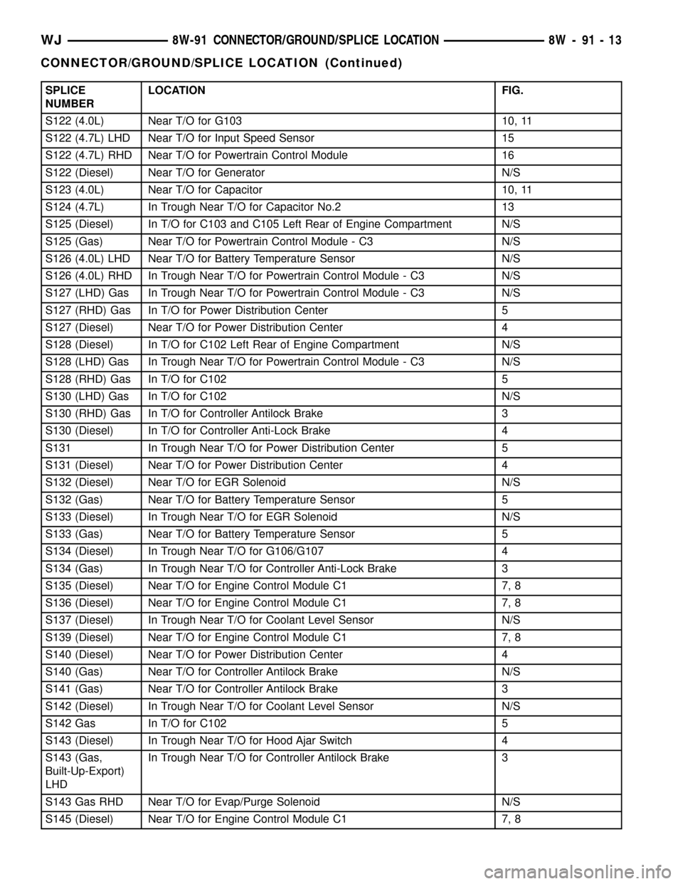
SPLICE
NUMBERLOCATION FIG.
S122 (4.0L) Near T/O for G103 10, 11
S122 (4.7L) LHD Near T/O for Input Speed Sensor 15
S122 (4.7L) RHD Near T/O for Powertrain Control Module 16
S122 (Diesel) Near T/O for Generator N/S
S123 (4.0L) Near T/O for Capacitor 10, 11
S124 (4.7L) In Trough Near T/O for Capacitor No.2 13
S125 (Diesel) In T/O for C103 and C105 Left Rear of Engine Compartment N/S
S125 (Gas) Near T/O for Powertrain Control Module - C3 N/S
S126 (4.0L) LHD Near T/O for Battery Temperature Sensor N/S
S126 (4.0L) RHD In Trough Near T/O for Powertrain Control Module - C3 N/S
S127 (LHD) Gas In Trough Near T/O for Powertrain Control Module - C3 N/S
S127 (RHD) Gas In T/O for Power Distribution Center 5
S127 (Diesel) Near T/O for Power Distribution Center 4
S128 (Diesel) In T/O for C102 Left Rear of Engine Compartment N/S
S128 (LHD) Gas In Trough Near T/O for Powertrain Control Module - C3 N/S
S128 (RHD) Gas In T/O for C102 5
S130 (LHD) Gas In T/O for C102 N/S
S130 (RHD) Gas In T/O for Controller Antilock Brake 3
S130 (Diesel) In T/O for Controller Anti-Lock Brake 4
S131 In Trough Near T/O for Power Distribution Center 5
S131 (Diesel) Near T/O for Power Distribution Center 4
S132 (Diesel) Near T/O for EGR Solenoid N/S
S132 (Gas) Near T/O for Battery Temperature Sensor 5
S133 (Diesel) In Trough Near T/O for EGR Solenoid N/S
S133 (Gas) Near T/O for Battery Temperature Sensor 5
S134 (Diesel) In Trough Near T/O for G106/G107 4
S134 (Gas) In Trough Near T/O for Controller Anti-Lock Brake 3
S135 (Diesel) Near T/O for Engine Control Module C1 7, 8
S136 (Diesel) Near T/O for Engine Control Module C1 7, 8
S137 (Diesel) In Trough Near T/O for Coolant Level Sensor N/S
S139 (Diesel) Near T/O for Engine Control Module C1 7, 8
S140 (Diesel) Near T/O for Power Distribution Center 4
S140 (Gas) Near T/O for Controller Antilock Brake N/S
S141 (Gas) Near T/O for Controller Antilock Brake 3
S142 (Diesel) In Trough Near T/O for Coolant Level Sensor N/S
S142 Gas In T/O for C102 5
S143 (Diesel) In Trough Near T/O for Hood Ajar Switch 4
S143 (Gas,
Built-Up-Export)
LHDIn Trough Near T/O for Controller Antilock Brake 3
S143 Gas RHD Near T/O for Evap/Purge Solenoid N/S
S145 (Diesel) Near T/O for Engine Control Module C1 7, 8
WJ8W-91 CONNECTOR/GROUND/SPLICE LOCATION 8W - 91 - 13
CONNECTOR/GROUND/SPLICE LOCATION (Continued)
Page 1189 of 2199

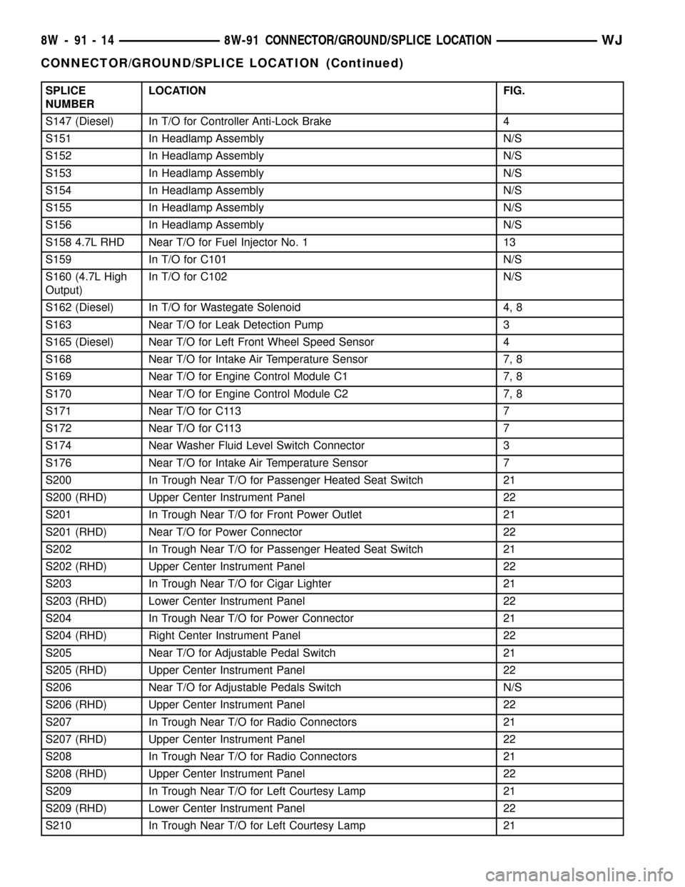
SPLICE
NUMBERLOCATION FIG.
S147 (Diesel) In T/O for Controller Anti-Lock Brake 4
S151 In Headlamp Assembly N/S
S152 In Headlamp Assembly N/S
S153 In Headlamp Assembly N/S
S154 In Headlamp Assembly N/S
S155 In Headlamp Assembly N/S
S156 In Headlamp Assembly N/S
S158 4.7L RHD Near T/O for Fuel Injector No. 1 13
S159 In T/O for C101 N/S
S160 (4.7L High
Output)In T/O for C102 N/S
S162 (Diesel) In T/O for Wastegate Solenoid 4, 8
S163 Near T/O for Leak Detection Pump 3
S165 (Diesel) Near T/O for Left Front Wheel Speed Sensor 4
S168 Near T/O for Intake Air Temperature Sensor 7, 8
S169 Near T/O for Engine Control Module C1 7, 8
S170 Near T/O for Engine Control Module C2 7, 8
S171 Near T/O for C113 7
S172 Near T/O for C113 7
S174 Near Washer Fluid Level Switch Connector 3
S176 Near T/O for Intake Air Temperature Sensor 7
S200 In Trough Near T/O for Passenger Heated Seat Switch 21
S200 (RHD) Upper Center Instrument Panel 22
S201 In Trough Near T/O for Front Power Outlet 21
S201 (RHD) Near T/O for Power Connector 22
S202 In Trough Near T/O for Passenger Heated Seat Switch 21
S202 (RHD) Upper Center Instrument Panel 22
S203 In Trough Near T/O for Cigar Lighter 21
S203 (RHD) Lower Center Instrument Panel 22
S204 In Trough Near T/O for Power Connector 21
S204 (RHD) Right Center Instrument Panel 22
S205 Near T/O for Adjustable Pedal Switch 21
S205 (RHD) Upper Center Instrument Panel 22
S206 Near T/O for Adjustable Pedals Switch N/S
S206 (RHD) Upper Center Instrument Panel 22
S207 In Trough Near T/O for Radio Connectors 21
S207 (RHD) Upper Center Instrument Panel 22
S208 In Trough Near T/O for Radio Connectors 21
S208 (RHD) Upper Center Instrument Panel 22
S209 In Trough Near T/O for Left Courtesy Lamp 21
S209 (RHD) Lower Center Instrument Panel 22
S210 In Trough Near T/O for Left Courtesy Lamp 21
8W - 91 - 14 8W-91 CONNECTOR/GROUND/SPLICE LOCATIONWJ
CONNECTOR/GROUND/SPLICE LOCATION (Continued)
Page 1300 of 2199

INSTALLATION
A gear-type oil pump is mounted at the underside
of the cylinder block opposite the No.4 main bearing.
(1) Install the oil pump on the cylinder block using
a replacement gasket. Tighten the bolts to 23 N´m
(17 ft. lbs.) torque.
(2) Install the oil pan (Refer to 9 - ENGINE/LU-
BRICATION/OIL PAN - INSTALLATION).
(3) Fill the oil pan with oil to the specified level.
INTAKE MANIFOLD
DESCRIPTION
The intake manifold (Fig. 83) is made of cast alu-
minum and uses eleven bolts to mount to the cylin-
der head. This mounting style improves sealing and
reduces the chance of leaks.
DIAGNOSIS AND TESTING - INTAKE
MANIFOLD LEAKAGE
An intake manifold air leak is characterized by
lower than normal manifold vacuum. Also, one or
more cylinders may not be functioning.
WARNING: USE EXTREME CAUTION WHEN THE
ENGINE IS OPERATING. DO NOT STAND IN A
DIRECT LINE WITH THE FAN. DO NOT PUT YOUR
HANDS NEAR THE PULLEYS, BELTS OR THE FAN.
DO NOT WEAR LOOSE CLOTHING.
(1) Start the engine.
(2) Spray a small stream of water at the suspected
leak area.
(3) If a change in RPM is observed the area of the
suspected leak has been found.
(4) Repair as required.
REMOVAL
NOTE: THE ENGINE INTAKE AND EXHAUST MANI-
FOLD MUST BE REMOVED AND INSTALLED
TOGETHER. THE MANIFOLDS USE A COMMON
GASKET AT THE CYLINDER HEAD.
(1) Disconnect the battery negative cable.
(2) Remove air cleaner inlet hose from the resona-
tor assembly.
(3) Remove the air cleaner assembly.
(4) Remove the throttle cable, vehicle speed control
cable (if equipped) and the transmission line pres-
sure cable (Refer to 21 - TRANSMISSION/TRANS-
AXLE/AUTOMATIC - AW4/THROTTLE VALVE
CABLE - REMOVAL).
(5) Disconnect the following electrical connections
and secure their harness out of the way:
²Throttle Position Sensor
²Idle Air Control Motor
²Coolant Temperature Sensor (at thermostat
housing)
²Intake Air Temperature Sensor
²Oxygen Sensor
²Crank Position Sensor
²Six (6) Fuel Injector Connectors
²Manifold Absolute Pressure (MAP) Sensor.
(6) Disconnect HVAC, and Brake Booster vacuum
supply hoses at the intake manifold.
(7) Perform the fuel pressure release procedure.
(Refer to 14 - FUEL SYSTEM/FUEL DELIVERY -
STANDARD PROCEDURE).
(8) Disconnect and remove the fuel system supply
line from the fuel rail assembly.
(9) Remove the accessory drive belt (Refer to 7 -
COOLING/ACCESSORY DRIVE/DRIVE BELTS -
REMOVAL).
(10) Remove the power steering pump from the
intake manifold and set aside.
(11) Raise the vehicle.
(12) Disconnect the exhaust pipes from the engine
exhaust manifolds.
(13) Lower the vehicle.
(14) Remove the intake manifold and exhaust
manifold bolts and manifolds (Fig. 84).
INSTALLATION
If the manifold is being replaced, ensure all the fit-
ting, etc. are transferred to the replacement mani-
fold.
(1) Install a new engine exhaust/intake manifold
gasket over the alignment dowels on the cylinder
head.
(2) Position the engine exhaust manifolds to the
cylinder head. Install fastener Number 3 and finger
tighten at this time (Fig. 84).
Fig. 83 Intake Manifold 4.0L Engine
WJENGINE - 4.0L 9 - 57
OIL PUMP (Continued)
Page 1379 of 2199

INTAKE MANIFOLD
DESCRIPTION
The intake manifold is made of a composite mate-
rial and features long runners which maximizes low
end torque. The intake manifold uses single plane
sealing which consist of eight individual press in
place port gaskets to prevent leaks. Eight studs and
two bolts are used to fasten the intake to the head.
DIAGNOSIS AND TESTINGÐINTAKE
MANIFOLD LEAKAGE
An intake manifold air leak is characterized by
lower than normal manifold vacuum. Also, one or
more cylinders may not be functioning.
WARNING: USE EXTREME CAUTION WHEN THE
ENGINE IS OPERATING. DO NOT STAND IN A
DIRECT LINE WITH THE FAN. DO NOT PUT YOUR
HANDS NEAR THE PULLEYS, BELTS OR THE FAN.
DO NOT WEAR LOOSE CLOTHING.
(1) Start the engine.
(2) Spray a small stream of water at the suspected
leak area.
(3) If a change in RPM is observed the area of the
suspected leak has been found.
(4) Repair as required.
REMOVAL
(1) Disconnect negative cable from battery.
(2) Remove air cleaner housing and throttle body
resonator (Fig. 104).
(3) Disconnect throttle and speed control cables.
(4) Disconnect electrical connectors for the follow-
ing components:
²Manifold Absolute Pressure (MAP) Sensor
²Intake Air Temperature (IAT) Sensor
²Throttle Position (TPS) Sensor
²Coolant Temperature (CTS) Sensor
²Idle Air Control (IAC) Motor
(5) Disconnect vapor purge hose, brake booster
hose, speed control servo hose, positive crankcase
ventilation (PCV) hose.
Fig. 102 Measuring Clearance Over Rotors
1 - STRAIGHT EDGE
2 - FEELER GAUGE
Fig. 103 Oil Pump and Primary Timing Chain
Tensioner Tightening Sequence
Fig. 104 Throttle Body Resonator
1 - THROTTLE BODY RESONATOR
2 - BOLT
3 - BOLT
9 - 136 ENGINE - 4.7LWJ
OIL PUMP (Continued)
Page 1381 of 2199

(7) Connect throttle cable and speed control cable
to throttle body.
(8) Install fuel rail (Refer to 14 - FUEL SYSTEM/
FUEL DELIVERY/FUEL RAIL - INSTALLATION).
(9) Install ignition coil towers (Refer to 8 - ELEC-
TRICAL/IGNITION CONTROL/IGNITION COIL -
INSTALLATION).
(10) Install coolant temperature sensor (Refer to 7
- COOLING/ENGINE/ENGINE COOLANT TEMP
SENSOR - INSTALLATION).
(11) Connect electrical connectors for the following
components:
²Manifold Absolute Pressure (MAP) Sensor
²Intake Air Temperature (IAT) Sensor
²Throttle Position (TPS) Sensor
²Coolant Temperature (CTS) Sensor
²Idle Air Control (IAC) Motor
²Ignition coil towers
²Fuel injectors
(12) Install top oil dipstick tube retaining bolt and
ground strap.
(13) Install right side engine lifting stud.
(14) Install generator including electrical connec-
tions (Refer to 8 - ELECTRICAL/CHARGING/GEN-
ERATOR - INSTALLATION).
(15) Connect Vapor purge hose, Brake booster
hose, Speed control servo hose, Positive crankcase
ventilation (PCV) hose.
(16) Install air conditioning compressor including
electrical connections.
(17) Fill cooling system (Refer to 7 - COOLING -
STANDARD PROCEDURE).
(18) Install accessory drive belt (Refer to 7 -
COOLING/ACCESSORY DRIVE/DRIVE BELTS -
INSTALLATION).
(19) Install cowl to hood seal (Refer to 23 - BODY/
WEATHERSTRIP/SEALS/COWL WEATHERSTRIP -
INSTALLATION).
(20) Install air cleaner housing and throttle body
resonator. Tighten resonator bolts 4.5 N´m (40 in.
lbs.).
(21) Connect negative cable to battery.
EXHAUST MANIFOLD - LEFT
DESCRIPTION
The exhaust manifolds are log style with a pat-
ented flow enhancing design to maximize perfor-
mance. The exhaust manifolds are made of high
silicon molybdenum cast iron. A perforated core
graphite exhaust manifold gasket is used to improve
sealing to the cylinder head. The exhaust manifolds
are covered by a three layer laminated heat shield
for thermal protection and noise reduction. The heat
shields are fastened with a torque prevailing nutthat is backed off slightly to allow for the thermal
expansion of the exhaust manifold.
REMOVAL
(1) Disconnect negative cable for battery.
(2) Hoist vehicle.
(3) Disconnect exhaust pipe at manifold.
(4) Lower vehicle.
(5) Remove air cleaner housing and tube.
(6) Remove the front two exhaust heat shield
retaining fasteners. Raise vehicle and remove the
fasteners at rear of heat shield.
(7) Remove heat shield (Fig. 107).
(8) Lower vehicle and remove the upper exhaust
manifold retaining bolts (Fig. 107).
(9) Raise vehicle and remove the lower exhaust
manifold retaining bolts (Fig. 107).
(10) Remove exhaust manifold and gasket (Fig.
107). Manifold is removed from below the engine
compartment.
CLEANING
(1) Clean the exhaust manifold using a suitable
cleaning solvent, then allow to air dry.
(2) Clean all gasket residue from the manifold
mating surface.
INSPECTION
(1) Inspect the exhaust manifold for cracks in the
mating surface and at every mounting bolt hole.
(2) Using a straight edge and a feeler gauge, check
the mating surface for warp and twist.
(3) Inspect the manifold to exhaust pipe mating
surface for cracks, gouges, or other damage that
would prevent sealing.
INSTALLATION
(1) Install exhaust manifold and gasket from below
engine compartment.
(2) Install lower exhaust manifold fasteners (Fig.
107). DO NOT tighten until all fasteners are in
place.
(3) Lower vehicle and install upper exhaust mani-
fold fasteners (Fig. 107). Tighten all manifold bolts
starting at center and working outward to 25 N´m
(18 ft. lbs.).
CAUTION: Over tightening heat shield fasteners,
may cause shield to distort and/or crack.
(4) Install exhaust manifold heat shield (Fig. 107).
Tighten fasteners to 8 N´m (72 in. lbs.), then loosen
45 degrees.
(5) Install air cleaner housing and tube.
(6) Connect exhaust pipe to manifold.
(7) Connect negative cable to battery.
9 - 138 ENGINE - 4.7LWJ
INTAKE MANIFOLD (Continued)
Page 1453 of 2199

(8) Inspect system body grounds for loose or dirty
connections. Refer to Group 8, Wiring for ground
locations.
(9) Verify crankcase ventilation (CCV) operation.
Refer to Emission Control System for additional
information.
(10) Inspect all fuel line quick-connect fittings for
damage or leaks.
(11) Verify hose connections to all ports of vacuum
fittings on intake manifold, and for emission system
are tight and not leaking.
(12) Inspect accelerator cable, transmission throt-
tle cable (if equipped) and speed control cable connec-
tions (if equipped). Check their connections to
throttle body linkage for any binding or restrictions.
(13) Verify vacuum booster hose is firmly con-
nected to fitting on intake manifold. Also check con-
nection to brake vacuum booster.(14) Inspect air cleaner inlet and air cleaner ele-
ment for dirt or restrictions.
(15) Inspect radiator grille area, radiator fins and
air conditioning condenser for restrictions.
(16) 4.0L Engine: Verify MAP, Intake Manifold Air
Temperature (IAT) sensor, TPS and Idle Air Control
(IAC) motor connectors are firmly connected (Fig. 9).
Be sure throttle body mounting bolts (Fig. 9)are
tight.
(17) 4.7L Engine: Verify Intake Manifold Air Tem-
perature (IAT) sensor, TPS and Idle Air Control (IAC)
motor connectors are firmly connected (Fig. 10). Be
sure throttle body mounting bolts (Fig. 10)are tight.
Fig. 8 Crankshaft Position SensorÐ4.7L V-8 Engine
1 - CRANKSHAFT POSITION SENSOR
2-STARTER
3 - ELEC. CONNECTOR
Fig. 9 IAT, MAP, IAC, TPS Sensor LocationsÐ4.0L
Engine
1 - MOUNTING BOLTS (4)
2 - THROTTLE BODY
3 - IAC MOTOR
4 - ELEC. CONN.
5 - TPS
6 - MAP SENSOR
7 - ELEC. CONN.
8 - IAT SENSOR
9 - ELEC. CONN.
14 - 34 FUEL INJECTIONWJ
FUEL INJECTION (Continued)
Page 1481 of 2199

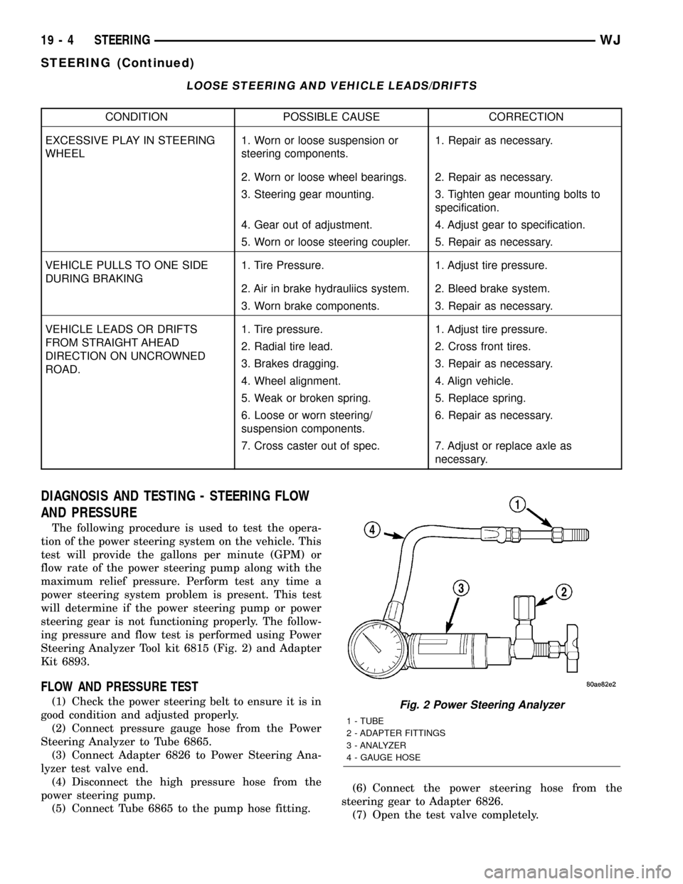
LOOSE STEERING AND VEHICLE LEADS/DRIFTS
CONDITION POSSIBLE CAUSE CORRECTION
EXCESSIVE PLAY IN STEERING
WHEEL1. Worn or loose suspension or
steering components.1. Repair as necessary.
2. Worn or loose wheel bearings. 2. Repair as necessary.
3. Steering gear mounting. 3. Tighten gear mounting bolts to
specification.
4. Gear out of adjustment. 4. Adjust gear to specification.
5. Worn or loose steering coupler. 5. Repair as necessary.
VEHICLE PULLS TO ONE SIDE
DURING BRAKING1. Tire Pressure. 1. Adjust tire pressure.
2. Air in brake hydrauliics system. 2. Bleed brake system.
3. Worn brake components. 3. Repair as necessary.
VEHICLE LEADS OR DRIFTS
FROM STRAIGHT AHEAD
DIRECTION ON UNCROWNED
ROAD.1. Tire pressure. 1. Adjust tire pressure.
2. Radial tire lead. 2. Cross front tires.
3. Brakes dragging. 3. Repair as necessary.
4. Wheel alignment. 4. Align vehicle.
5. Weak or broken spring. 5. Replace spring.
6. Loose or worn steering/
suspension components.6. Repair as necessary.
7. Cross caster out of spec. 7. Adjust or replace axle as
necessary.
DIAGNOSIS AND TESTING - STEERING FLOW
AND PRESSURE
The following procedure is used to test the opera-
tion of the power steering system on the vehicle. This
test will provide the gallons per minute (GPM) or
flow rate of the power steering pump along with the
maximum relief pressure. Perform test any time a
power steering system problem is present. This test
will determine if the power steering pump or power
steering gear is not functioning properly. The follow-
ing pressure and flow test is performed using Power
Steering Analyzer Tool kit 6815 (Fig. 2) and Adapter
Kit 6893.
FLOW AND PRESSURE TEST
(1) Check the power steering belt to ensure it is in
good condition and adjusted properly.
(2) Connect pressure gauge hose from the Power
Steering Analyzer to Tube 6865.
(3) Connect Adapter 6826 to Power Steering Ana-
lyzer test valve end.
(4) Disconnect the high pressure hose from the
power steering pump.
(5) Connect Tube 6865 to the pump hose fitting.(6) Connect the power steering hose from the
steering gear to Adapter 6826.
(7) Open the test valve completely.Fig. 2 Power Steering Analyzer
1 - TUBE
2 - ADAPTER FITTINGS
3 - ANALYZER
4 - GAUGE HOSE
19 - 4 STEERINGWJ
STEERING (Continued)
Page 1489 of 2199

SPECIFICATIONS
TORQUE CHART
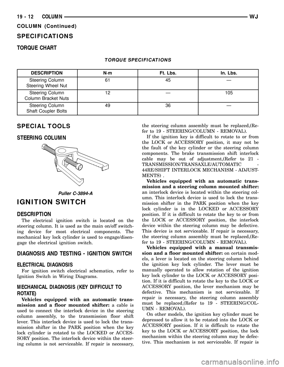
TORQUE SPECIFICATIONS
DESCRIPTION N´m Ft. Lbs. In. Lbs.
Steering Column
Steering Wheel Nut61 45 Ð
Steering Column
Column Bracket Nuts12 Ð 105
Steering Column
Shaft Coupler Bolts49 36 Ð
SPECIAL TOOLS
STEERING COLUMN
IGNITION SWITCH
DESCRIPTION
The electrical ignition switch is located on the
steering column. It is used as the main on/off switch-
ing device for most electrical components. The
mechanical key lock cylinder is used to engage/disen-
gage the electrical ignition switch.
DIAGNOSIS AND TESTING - IGNITION SWITCH
ELECTRICAL DIAGNOSIS
For ignition switch electrical schematics, refer to
Ignition Switch in Wiring Diagrams.
MECHANICAL DIAGNOSIS (KEY DIFFICULT TO
ROTATE)
Vehicles equipped with an automatic trans-
mission and a floor mounted shifter:a cable is
used to connect the interlock device in the steering
column assembly, to the transmission floor shift
lever. This interlock device is used to lock the trans-
mission shifter in the PARK position when the key
lock cylinder is rotated to the LOCKED or ACCES-
SORY position. The interlock device within the steer-
ing column is not serviceable. If repair is necessary,the steering column assembly must be replaced,(Re-
fer to 19 - STEERING/COLUMN - REMOVAL).
If the ignition key is difficult to rotate to or from
the LOCK or ACCESSORY position, it may not be
the fault of the key cylinder or the steering column
components. The brake transmission shift interlock
cable may be out of adjustment,(Refer to 21 -
TRANSMISSION/TRANSAXLE/AUTOMATIC -
44RE/SHIFT INTERLOCK MECHANISM - ADJUST-
MENTS) .
Vehicles equipped with an automatic trans-
mission and a steering column mounted shifter:
an interlock device is located within the steering col-
umn. This interlock device is used to lock the trans-
mission shifter in the PARK position when the key
lock cylinder is in the LOCKED or ACCESSORY
position. If it is difficult to rotate the key to or from
the LOCK or ACCESSORY position, the interlock
device within the steering column may be defective.
This device is not serviceable. If repair is necessary,
the steering column assembly must be replaced,(Re-
fer to 19 - STEERING/COLUMN - REMOVAL).
Vehicles equipped with a manual transmis-
sion and a floor mounted shifter:on certain mod-
els, a lever is located on the steering column behind
the ignition key lock cylinder. The lever must be
manually operated to allow rotation of the ignition
key lock cylinder to the LOCK or ACCESSORY posi-
tion. If it is difficult to rotate the key to the LOCK or
ACCESSORY position, the lever mechanism may be
defective. This mechanism is not serviceable. If
repair is necessary, the steering column assembly
must be replaced,(Refer to 19 - STEERING/COL-
UMN - REMOVAL).
On other models, the ignition key cylinder must be
depressed to allow it to be rotated into the LOCK or
ACCESSORY position. If it is difficult to rotate the
key to the LOCK or ACCESSORY position, the lock
mechanism within the steering column may be defec-
tive. This mechanism is not serviceable. If repair is
Puller C-3894-A
19 - 12 COLUMNWJ
COLUMN (Continued)