2003 JEEP GRAND CHEROKEE roof rack
[x] Cancel search: roof rackPage 626 of 2199

the more frequently the RSM will send wipe com-
mands to the BCM to operate the front wiper system.
The RSM operates on battery current received
through a fuse in the Junction Block (JB) on a fused
B(+) circuit. This circuit is switched by the power
accessory (sunroof) delay relay in the JB so that the
RSM will operate whenever the relay is energized by
the BCM. The RSM receives ground at all times
through a take out of the left body wire harness with
an eyelet terminal that is secured by a ground screw
to the front seat crossmember on the floor panel
under the left front seat. It is important to note that
the default condition for the wiper system is auto-
matic wipers Off; therefore, if no message is received
from the RSM by the BCM for more than about five
seconds, the automatic wipers will be disabled and
the BCM will default the front wiper system opera-
tion to the low speed continuous wipe mode.
The RSM ground and battery current inputs can be
diagnosed using conventional diagnostic tools and
methods. However, conventional diagnostic methods
may not prove conclusive in the diagnosis of the RSM
internal circuitry, the BCM, the PCI data bus net-
work, or the electronic messages received and trans-
mitted by the RSM over the PCI data bus. The most
reliable, efficient, and accurate means to diagnose
the RSM requires the use of a DRBIIItscan tool.
Refer to the appropriate diagnostic information.
REMOVAL
WARNING: ON VEHICLES EQUIPPED WITH AIR-
BAGS, DISABLE THE SUPPLEMENTAL RESTRAINT
SYSTEM BEFORE ATTEMPTING ANY STEERING
WHEEL, STEERING COLUMN, DRIVER AIRBAG,
PASSENGER AIRBAG, SIDE CURTAIN AIRBAG,
FRONT IMPACT SENSOR, SIDE IMPACT SENSOR,
OR INSTRUMENT PANEL COMPONENT DIAGNOSIS
OR SERVICE. DISCONNECT AND ISOLATE THE
BATTERY NEGATIVE (GROUND) CABLE, THEN
WAIT TWO MINUTES FOR THE SYSTEM CAPACI-
TOR TO DISCHARGE BEFORE PERFORMING FUR-
THER DIAGNOSIS OR SERVICE. THIS IS THE ONLY
SURE WAY TO DISABLE THE SUPPLEMENTAL
RESTRAINT SYSTEM. FAILURE TO TAKE THE
PROPER PRECAUTIONS COULD RESULT IN ACCI-
DENTAL AIRBAG DEPLOYMENT AND POSSIBLE
PERSONAL INJURY.
(1) Disconnect and isolate the battery negative
cable.
(2) Adjust the inside rear view mirror on the wind-
shield downward far enough to access the lower edge
of the Rain Sensor Module (RSM) trim cover (Fig.
15).
(3) Using a small thin-bladed screwdriver inserted
into the notch at the bottom of trim cover, gently prythe trim cover away from the windshield glass until
it unsnaps from the RSM.
(4) Using a small thin-bladed screwdriver, gently
pry the spring clips on each side of the RSM away
from the bracket on the windshield.
(5) Pull the RSM away from the bracket on the
windshield far enough to access and disconnect the
overhead wire harness connector for the module from
the module connector receptacle.
(6) Remove the RSM from above the inside rear
view mirror.
INSTALLATION
WARNING: ON VEHICLES EQUIPPED WITH AIR-
BAGS, DISABLE THE SUPPLEMENTAL RESTRAINT
SYSTEM BEFORE ATTEMPTING ANY STEERING
WHEEL, STEERING COLUMN, DRIVER AIRBAG,
PASSENGER AIRBAG, SIDE CURTAIN AIRBAG,
FRONT IMPACT SENSOR, SIDE IMPACT SENSOR,
OR INSTRUMENT PANEL COMPONENT DIAGNOSIS
OR SERVICE. DISCONNECT AND ISOLATE THE
BATTERY NEGATIVE (GROUND) CABLE, THEN
WAIT TWO MINUTES FOR THE SYSTEM CAPACI-
TOR TO DISCHARGE BEFORE PERFORMING FUR-
THER DIAGNOSIS OR SERVICE. THIS IS THE ONLY
SURE WAY TO DISABLE THE SUPPLEMENTAL
RESTRAINT SYSTEM. FAILURE TO TAKE THE
PROPER PRECAUTIONS COULD RESULT IN ACCI-
DENTAL AIRBAG DEPLOYMENT AND POSSIBLE
PERSONAL INJURY.
Fig. 15 Rain Sensor Module Remove/Install
1 - OVERHEAD CONSOLE
2 - REAR VIEW MIRROR CONNECTOR
3 - BRACKET
4 - REAR VIEW MIRROR BUTTON
5 - SPRING CLIP (2)
6 - RAIN SENSOR MODULE
7 - TRIM COVER
8 - WIRE HARNESS CONNECTOR
WJFRONT WIPERS/WASHERS 8R - 19
RAIN SENSOR MODULE (Continued)
Page 1874 of 2199
BODY
TABLE OF CONTENTS
page page
BODY
DIAGNOSIS AND TESTING
WATER LEAKS........................1
WIND NOISE..........................2
STANDARD PROCEDURE
STANDARD PROCEDURE - BODY
LUBRICATION.........................2
STANDARD PROCEDURE - DRILLING AND
WELDING............................3
SPECIFICATIONS
BODY LUBRICANTS....................3
SPECIFICATIONS - TORQUE.............4
SPECIAL TOOLS
BODY...............................4DECKLID/HATCH/LIFTGATE/TAILGATE........5
DOOR - FRONT.........................11
DOORS - REAR.........................19
EXTERIOR.............................25
HOOD.................................33
INSTRUMENT PANEL SYSTEM.............36
INTERIOR..............................69
PAINT.................................81
SEATS................................83
STATIONARY GLASS.....................93
SUNROOF.............................96
WEATHERSTRIP/SEALS..................105
BODY STRUCTURE.....................112
BODY
DIAGNOSIS AND TESTING
WATER LEAKS
Water leaks can be caused by poor sealing,
improper body component alignment, body seam
porosity, missing plugs, or blocked drain holes. Cen-
trifugal and gravitational force can cause water to
drip from a location away from the actual leak point,
making leak detection difficult. All body sealing
points should be water tight in normal wet-driving
conditions. Water flowing downward from the front of
the vehicle should not enter the passenger or luggage
compartment. Moving sealing surfaces will not
always seal water tight under all conditions. At
times, side glass or door seals will allow water to
enter the passenger compartment during high pres-
sure washing or hard driving rain (severe) condi-
tions. Overcompensating on door or glass
adjustments to stop a water leak that occurs under
severe conditions can cause premature seal wear and
excessive closing or latching effort. After completing
a repair, water test vehicle to verify leak has stopped
before returning vehicle to use.
VISUAL INSPECTION BEFORE WATER LEAK TESTS
Verify that floor and body plugs are in place, body
drains are clear, and body components are properly
aligned and sealed. If component alignment or seal-
ing is necessary, refer to the appropriate section of
this group for proper procedures.
WATER LEAK TESTS
WARNING: DO NOT USE ELECTRIC SHOP LIGHTS
OR TOOLS IN WATER TEST AREA. PERSONAL
INJURY CAN RESULT.
When the conditions causing a water leak have
been determined, simulate the conditions as closely
as possible.
²If a leak occurs with the vehicle parked in a
steady light rain, flood the leak area with an open-
ended garden hose.
²If a leak occurs while driving at highway speeds
in a steady rain, test the leak area with a reasonable
velocity stream or fan spray of water. Direct the
spray in a direction comparable to actual conditions.
²If a leak occurs when the vehicle is parked on an
incline, hoist the end or side of the vehicle to simu-
late this condition. This method can be used when
the leak occurs when the vehicle accelerates, stops or
turns. If the leak occurs on acceleration, hoist the
front of the vehicle. If the leak occurs when braking,
hoist the back of the vehicle. If the leak occurs on left
turns, hoist the left side of the vehicle. If the leak
occurs on right turns, hoist the right side of the vehi-
cle. For hoisting recommendations refer to Group 0,
Lubrication and Maintenance, General Information
section.
WATER LEAK DETECTION
To detect a water leak point-of-entry, do a water
test and watch for water tracks or droplets forming
on the inside of the vehicle. If necessary, remove inte-
rior trim covers or panels to gain visual access to the
WJBODY 23 - 1
Page 1877 of 2199
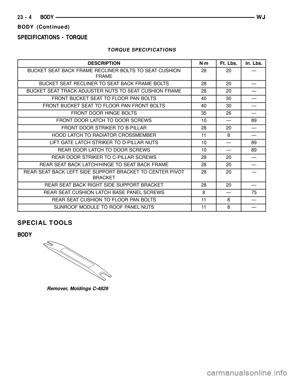
SPECIFICATIONS - TORQUE
TORQUE SPECIFICATIONS
DESCRIPTION N´m Ft. Lbs. In. Lbs.
BUCKET SEAT BACK FRAME RECLINER BOLTS TO SEAT CUSHION
FRAME28 20 Ð
BUCKET SEAT RECLINER TO SEAT BACK FRAME BOLTS 28 20 Ð
BUCKET SEAT TRACK ADJUSTER NUTS TO SEAT CUSHION FRAME 28 20 Ð
FRONT BUCKET SEAT TO FLOOR PAN BOLTS 40 30 Ð
FRONT BUCKET SEAT TO FLOOR PAN FRONT BOLTS 40 30 Ð
FRONT DOOR HINGE BOLTS 35 26 Ð
FRONT DOOR LATCH TO DOOR SCREWS 10 Ð 89
FRONT DOOR STRIKER TO B-PILLAR 28 20 Ð
HOOD LATCH TO RADIATOR CROSSMEMBER 11 8 Ð
LIFT GATE LATCH STRIKER TO D-PILLAR NUTS 10 Ð 89
REAR DOOR LATCH TO DOOR SCREWS 10 Ð 89
REAR DOOR STRIKER TO C-PILLAR SCREWS 28 20 Ð
REAR SEAT BACK LATCH/HINGE TO SEAT BACK FRAME 28 20 Ð
REAR SEAT BACK LEFT SIDE SUPPORT BRACKET TO CENTER PIVOT
BRACKET28 20 Ð
REAR SEAT BACK RIGHT SIDE SUPPORT BRACKET 28 20 Ð
REAR SEAT CUSHION LATCH BASE PANEL SCREWS 8 Ð 75
REAR SEAT CUSHION TO FLOOR PAN BOLTS 11 8 Ð
SUNROOF MODULE TO ROOF PANEL NUTS 11 8 Ð
SPECIAL TOOLS
BODY
Remover, Moldings C-4829
23 - 4 BODYWJ
BODY (Continued)
Page 1903 of 2199
(3) Install fascia, refer to (Refer to 13 - FRAMES
& BUMPERS/BUMPERS/FRONT FASCIA - INSTAL-
LATION).
HEADLAMP MOUNTING
MODULE
REMOVAL
CAUTION: Take special care when handling the
HMM not to damage the upper mounting tabs. Step
#3 must be performed prior to removing HMM from
the vehicle to prevent damage to HMM.
(1) Remove fascia, refer to (Refer to 13 - FRAMES
& BUMPERS/BUMPERS/FRONT FASCIA - REMOV-
AL).
(2) Remove inner fender liner.
(3) Reach into the wheelhouse opening and disen-
gage the retainer attaching the HMM to each side of
the body.
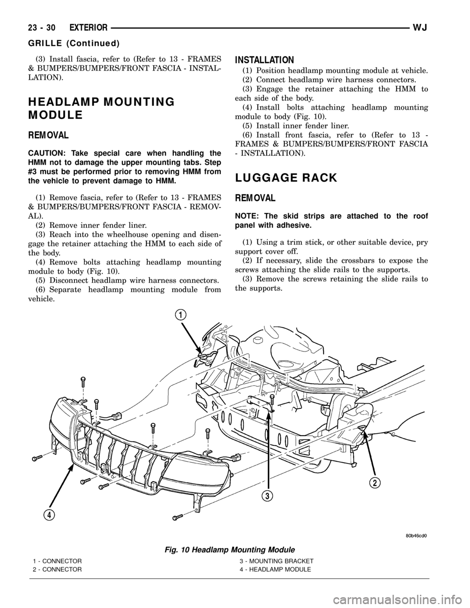
(4) Remove bolts attaching headlamp mounting
module to body (Fig. 10).
(5) Disconnect headlamp wire harness connectors.
(6) Separate headlamp mounting module from
vehicle.
INSTALLATION
(1) Position headlamp mounting module at vehicle.
(2) Connect headlamp wire harness connectors.
(3) Engage the retainer attaching the HMM to
each side of the body.
(4) Install bolts attaching headlamp mounting
module to body (Fig. 10).
(5) Install inner fender liner.
(6) Install front fascia, refer to (Refer to 13 -
FRAMES & BUMPERS/BUMPERS/FRONT FASCIA
- INSTALLATION).
LUGGAGE RACK
REMOVAL
NOTE: The skid strips are attached to the roof
panel with adhesive.
(1) Using a trim stick, or other suitable device, pry
support cover off.
(2) If necessary, slide the crossbars to expose the
screws attaching the slide rails to the supports.
(3) Remove the screws retaining the slide rails to
the supports.
Fig. 10 Headlamp Mounting Module
1 - CONNECTOR
2 - CONNECTOR3 - MOUNTING BRACKET
4 - HEADLAMP MODULE
23 - 30 EXTERIORWJ
GRILLE (Continued)
Page 1904 of 2199
(4) Remove the screws attaching the supports to
the roof panel.
(5) Separate the supports from the roof panel.
NOTE: If a crossbar needs to be serviced, the for-
ward or rearward supports will have to be removed.
INSTALLATION
(1) Position the supports on the roof panel and
install the screw. Be sure that the gasket is properly
seated.
(2) Position the luggage rack on the supports.
(3) Install the screws attaching the side rails to
the supports.
(4) Position the supports covers on the supports
and press into place.
SIDE VIEW MIRROR GLASS
REMOVAL
(1) With damaged mirror still on vehicle, position
mirror glass down and centered.
(2) Position a wide leverage device between the
bottom edge of the glass and the mirror shell.
(3) Firmly apply pressure in an upward direction
until glass assembly disengages from adapter plate.
(4) Disconnect the heater wire terminal, if
equipped, or the EC plug, if equipped.
INSTALLATION
(1) Connect the heater wire terminal or the EC
plug, if equipped.
(2) Position the replacement glass in the mirror
shell and align the four snap tabs with the four cav-
ities in the shell.
(3) Apply firm pressure inward until the replace-
ment glass assembly engages with the adapter plate.
Correct assembly will result in a firm click. Glass
assembly should exhibit even gaps to the shell when
complete.
(4) Pull lightly on corners of glass assembly to
ensure all four snaps are engaged and there is no
free play.
SIDE VIEW MIRROR
REMOVAL
(1) Remove door trim panel, refer to (Refer to 23 -
BODY/DOOR - FRONT/TRIM PANEL - REMOVAL).
(2) Disengage power mirror harness connector, if
equipped.
(3) Remove mirror flag seal.
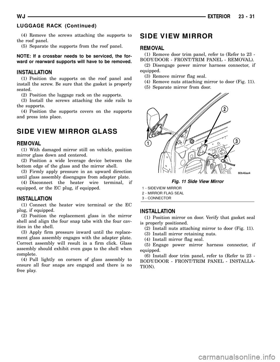
(4) Remove nuts attaching mirror to door (Fig. 11).
(5) Separate mirror from door.
INSTALLATION
(1) Position mirror on door. Verify that gasket seal
is properly positioned.
(2) Install nuts attaching mirror to door (Fig. 11).
(3) Install mirror retaining nuts.
(4) Install mirror flag seal.
(5) Engage power mirror harness connector, if
equipped.
(6) Install door trim panel, refer to (Refer to 23 -
BODY/DOOR - FRONT/TRIM PANEL - INSTALLA-
TION).
Fig. 11 Side View Mirror
1 - SIDEVIEW MIRROR
2 - MIRROR FLAG SEAL
3 - CONNECTOR
WJEXTERIOR 23 - 31
LUGGAGE RACK (Continued)
Page 1953 of 2199
INSTALLATION
(1) Position the bin hooks high in the slots on the
quarter trim panel.
(2) Push downward until the bin snaps into place.
(3) Install the hinge screws.
REAR VIEW MIRROR
REMOVAL
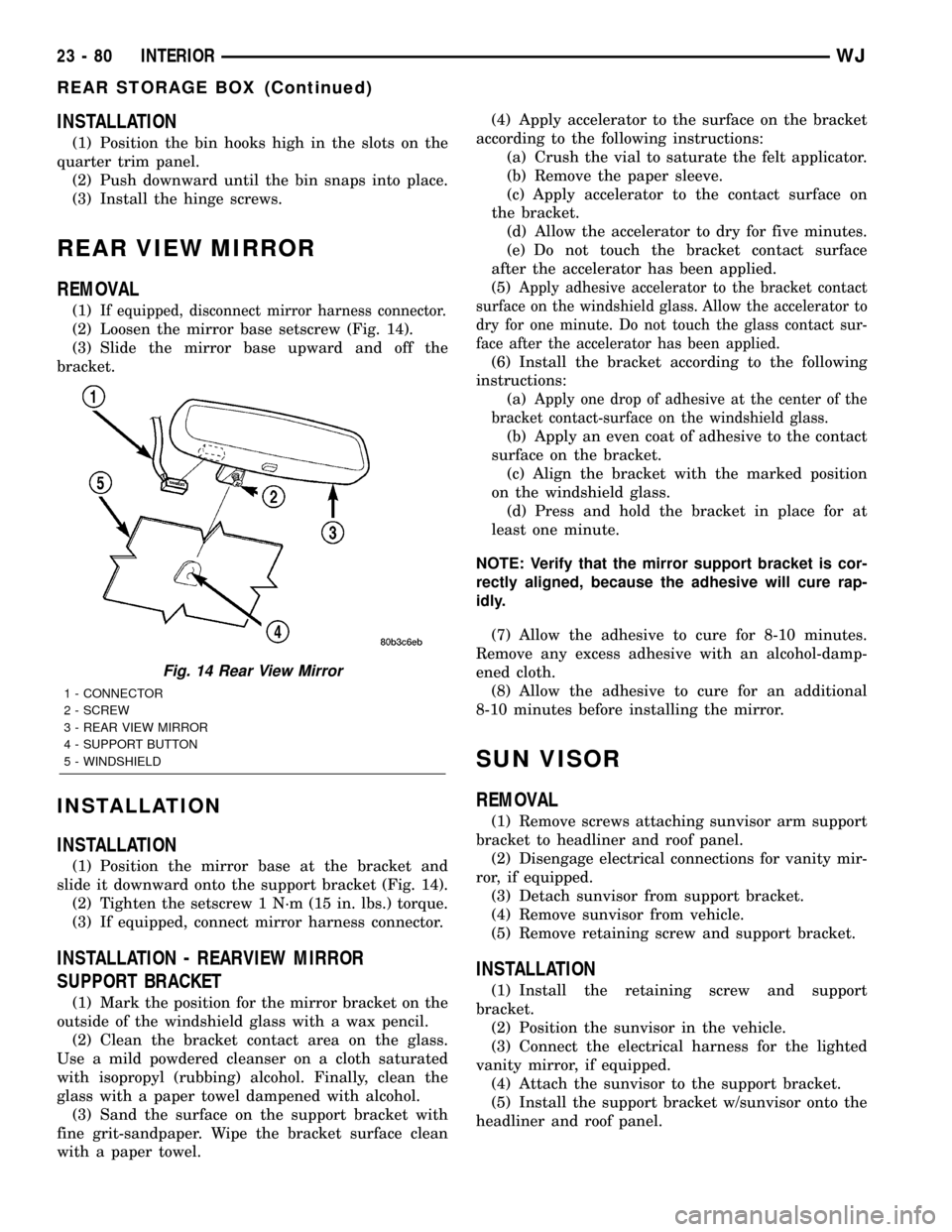
(1)If equipped, disconnect mirror harness connector.
(2) Loosen the mirror base setscrew (Fig. 14).
(3) Slide the mirror base upward and off the
bracket.
INSTALLATION
INSTALLATION
(1) Position the mirror base at the bracket and
slide it downward onto the support bracket (Fig. 14).
(2) Tighten the setscrew 1 N´m (15 in. lbs.) torque.
(3) If equipped, connect mirror harness connector.
INSTALLATION - REARVIEW MIRROR
SUPPORT BRACKET
(1) Mark the position for the mirror bracket on the
outside of the windshield glass with a wax pencil.
(2) Clean the bracket contact area on the glass.
Use a mild powdered cleanser on a cloth saturated
with isopropyl (rubbing) alcohol. Finally, clean the
glass with a paper towel dampened with alcohol.
(3) Sand the surface on the support bracket with
fine grit-sandpaper. Wipe the bracket surface clean
with a paper towel.(4) Apply accelerator to the surface on the bracket
according to the following instructions:
(a) Crush the vial to saturate the felt applicator.
(b) Remove the paper sleeve.
(c) Apply accelerator to the contact surface on
the bracket.
(d) Allow the accelerator to dry for five minutes.
(e) Do not touch the bracket contact surface
after the accelerator has been applied.
(5)
Apply adhesive accelerator to the bracket contact
surface on the windshield glass. Allow the accelerator to
dry for one minute. Do not touch the glass contact sur-
face after the accelerator has been applied.
(6) Install the bracket according to the following
instructions:
(a)
Apply one drop of adhesive at the center of the
bracket contact-surface on the windshield glass.
(b) Apply an even coat of adhesive to the contact
surface on the bracket.
(c) Align the bracket with the marked position
on the windshield glass.
(d) Press and hold the bracket in place for at
least one minute.
NOTE: Verify that the mirror support bracket is cor-
rectly aligned, because the adhesive will cure rap-
idly.
(7) Allow the adhesive to cure for 8-10 minutes.
Remove any excess adhesive with an alcohol-damp-
ened cloth.
(8) Allow the adhesive to cure for an additional
8-10 minutes before installing the mirror.
SUN VISOR
REMOVAL
(1) Remove screws attaching sunvisor arm support
bracket to headliner and roof panel.
(2) Disengage electrical connections for vanity mir-
ror, if equipped.
(3) Detach sunvisor from support bracket.
(4) Remove sunvisor from vehicle.
(5) Remove retaining screw and support bracket.
INSTALLATION
(1) Install the retaining screw and support
bracket.
(2) Position the sunvisor in the vehicle.
(3) Connect the electrical harness for the lighted
vanity mirror, if equipped.
(4) Attach the sunvisor to the support bracket.
(5) Install the support bracket w/sunvisor onto the
headliner and roof panel.
Fig. 14 Rear View Mirror
1 - CONNECTOR
2 - SCREW
3 - REAR VIEW MIRROR
4 - SUPPORT BUTTON
5 - WINDSHIELD
23 - 80 INTERIORWJ
REAR STORAGE BOX (Continued)
Page 1970 of 2199
releasing the control switch before the sunroof was
fully closed. The sunroof module has a water-man-
agement system. During washing high-pressure
water may be forced between the glass panel seal
and the roof opening. Normally this water will drain.
However, when some type of drying blower system is
used, like those found in automatic car washes, thewater may not have a chance to drain before the
blower forces air between the seal and the roof open-
ing. This causes the water to blow over the edge of
the module and onto the headlining.
Refer to (Fig. 1) Sunroof Assembly for exploded
view of the sunroof.
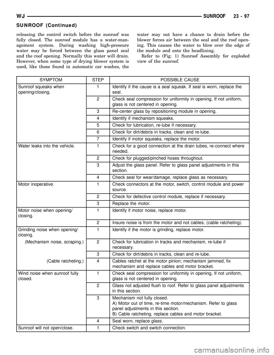
SYMPTOM STEP POSSIBLE CAUSE
Sunroof squeaks when
opening/closing.1 Identify if the cause is a seal squeak. If seal is worn, replace the
seal.
2 Check seal compression for uniformity in opening, If not uniform,
glass is not centered in opening.
3 Re-center glass by repositioning module in opening.
4 Identify if mechanism squeaks.
5 Check for lubrication, re-lube if necessary.
6 Check for dirt/debris in tracks, clean and re-lube.
7 Identify if motor squeaks, replace the motor.
Water leaks into the vehicle. 1 Check for a good connection at the drain tubes, re-connect where
needed.
2 Check for plugged/pinched hoses throughout.
3 Adjust the glass panel. Refer to glass panel adjustments in this
section.
4 Check seal for wear/damage, replace glass as necessary.
Motor inoperative. 1 Check connectors at the motor, switch, control module and power
source.
2 Check for defective control module, replace if necessary.
3 Replace the motor.
Motor noise when opening/
closing.1 Identify if motor noise, replace motor.
2 Insure noise is from the motor and not cables, (cable ratcheting).
Grinding noise when opening/
closing.1 Identify if the motor is grinding, replace motor.
(Mechanism noise, scraping.) 2 Check for lubrication in tracks and mechanism, re-lube if
necessary.
3 Check for dirt/debris in tracks, clean and re-lube.
(Cable ratcheting.) 4 Cables ratchet at the motor pinion; mechanism jammed, fix
mechanism and replace cables and motor bracket.
Wind noise when sunroof fully
closed.1 Check seal compression for uniformity in opening, If not uniform,
glass is not centered in opening.
2 Glass not adjusted flush to roof. Refer to glass panel adjustments
in this section.
3 Mechanism not fully closed.
A) Motor out of time, re-time motor/mechanism. Refer to glass
panel adjustments in this section.
B) Cable ratcheting, replace cables and motor bracket.
4 Seal worn, replace glass.
Sunroof will not open/close. 1 Check switch and switch connection.
WJSUNROOF 23 - 97
SUNROOF (Continued)
Page 1971 of 2199
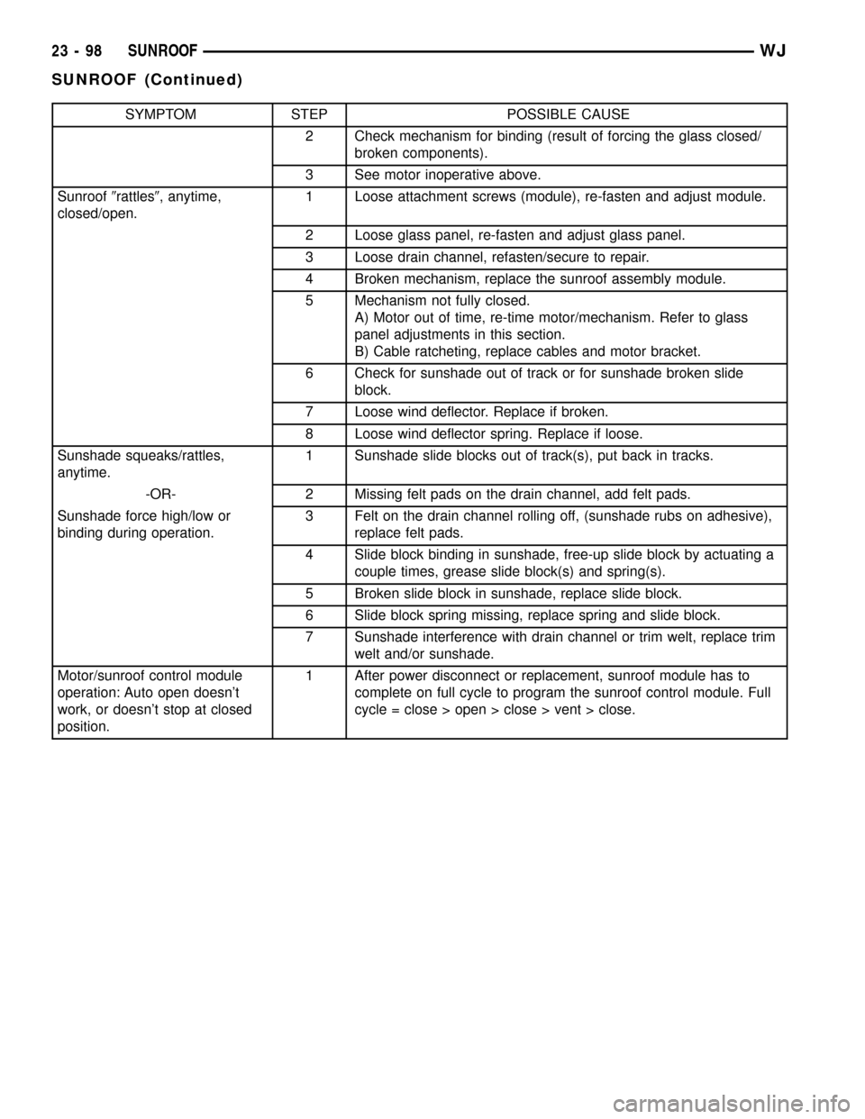
SYMPTOM STEP POSSIBLE CAUSE
2 Check mechanism for binding (result of forcing the glass closed/
broken components).
3 See motor inoperative above.
Sunroof9rattles9, anytime,
closed/open.1 Loose attachment screws (module), re-fasten and adjust module.
2 Loose glass panel, re-fasten and adjust glass panel.
3 Loose drain channel, refasten/secure to repair.
4 Broken mechanism, replace the sunroof assembly module.
5 Mechanism not fully closed.
A) Motor out of time, re-time motor/mechanism. Refer to glass
panel adjustments in this section.
B) Cable ratcheting, replace cables and motor bracket.
6 Check for sunshade out of track or for sunshade broken slide
block.
7 Loose wind deflector. Replace if broken.
8 Loose wind deflector spring. Replace if loose.
Sunshade squeaks/rattles,
anytime.1 Sunshade slide blocks out of track(s), put back in tracks.
-OR- 2 Missing felt pads on the drain channel, add felt pads.
Sunshade force high/low or
binding during operation.3 Felt on the drain channel rolling off, (sunshade rubs on adhesive),
replace felt pads.
4 Slide block binding in sunshade, free-up slide block by actuating a
couple times, grease slide block(s) and spring(s).
5 Broken slide block in sunshade, replace slide block.
6 Slide block spring missing, replace spring and slide block.
7 Sunshade interference with drain channel or trim welt, replace trim
welt and/or sunshade.
Motor/sunroof control module
operation: Auto open doesn't
work, or doesn't stop at closed
position.1 After power disconnect or replacement, sunroof module has to
complete on full cycle to program the sunroof control module. Full
cycle = close > open > close > vent > close.
23 - 98 SUNROOFWJ
SUNROOF (Continued)