2003 JEEP GRAND CHEROKEE fuel filter location
[x] Cancel search: fuel filter locationPage 1431 of 2199

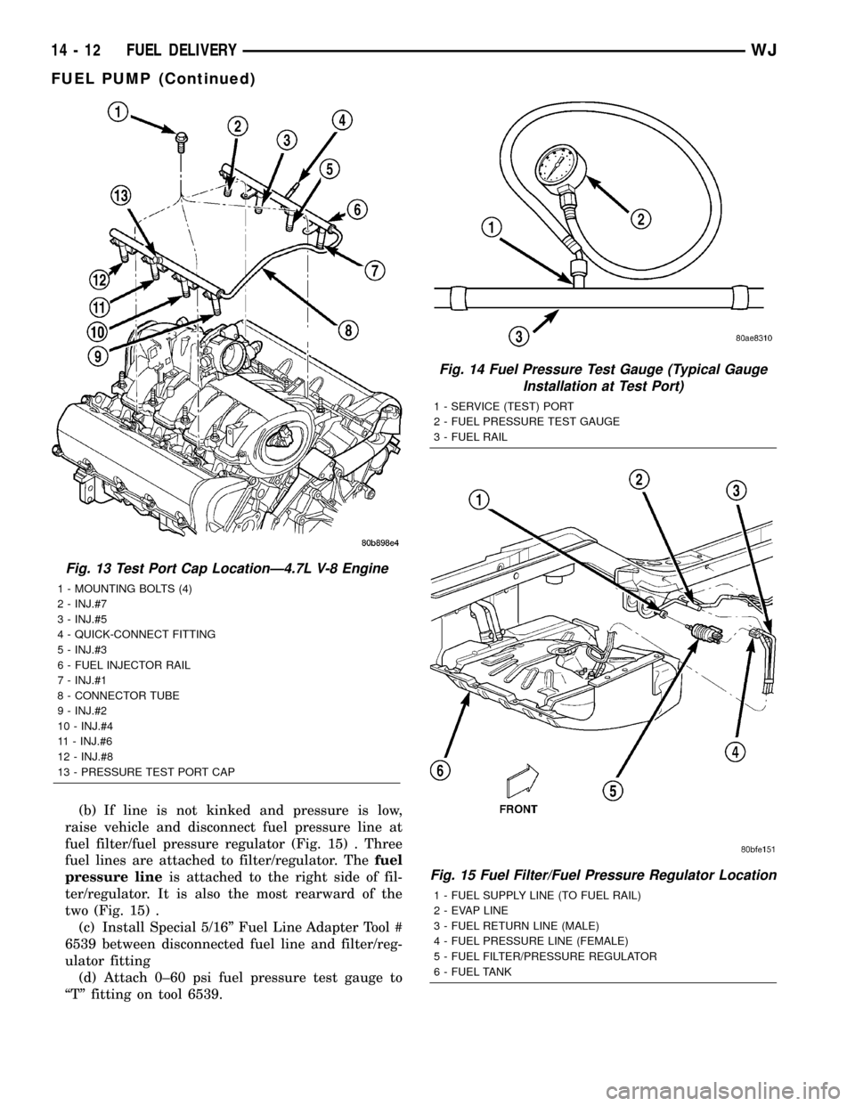
(b) If line is not kinked and pressure is low,
raise vehicle and disconnect fuel pressure line at
fuel filter/fuel pressure regulator (Fig. 15) . Three
fuel lines are attached to filter/regulator. Thefuel
pressure lineis attached to the right side of fil-
ter/regulator. It is also the most rearward of the
two (Fig. 15) .
(c) Install Special 5/16º Fuel Line Adapter Tool #
6539 between disconnected fuel line and filter/reg-
ulator fitting
(d) Attach 0±60 psi fuel pressure test gauge to
ªTº fitting on tool 6539.
Fig. 13 Test Port Cap LocationÐ4.7L V-8 Engine
1 - MOUNTING BOLTS (4)
2 - INJ.#7
3 - INJ.#5
4 - QUICK-CONNECT FITTING
5 - INJ.#3
6 - FUEL INJECTOR RAIL
7 - INJ.#1
8 - CONNECTOR TUBE
9 - INJ.#2
10 - INJ.#4
11 - INJ.#6
12 - INJ.#8
13 - PRESSURE TEST PORT CAP
Fig. 14 Fuel Pressure Test Gauge (Typical Gauge
Installation at Test Port)
1 - SERVICE (TEST) PORT
2 - FUEL PRESSURE TEST GAUGE
3 - FUEL RAIL
Fig. 15 Fuel Filter/Fuel Pressure Regulator Location
1 - FUEL SUPPLY LINE (TO FUEL RAIL)
2 - EVAP LINE
3 - FUEL RETURN LINE (MALE)
4 - FUEL PRESSURE LINE (FEMALE)
5 - FUEL FILTER/PRESSURE REGULATOR
6 - FUEL TANK
14 - 12 FUEL DELIVERYWJ
FUEL PUMP (Continued)
Page 1457 of 2199

(23) Inspect for pinched or leaking fuel tubes/lines.
Inspect for pinched, cracked or leaking fuel hoses.
(24) Inspect for exhaust system restrictions such
as pinched exhaust pipes, collapsed muffler or
plugged catalytic convertor.
(25) If equipped with automatic transmission, ver-
ify electrical harness is firmly connected to park/neu-
tral switch and to transmission components.
(26) Verify fuel pump module pigtail harness elec-
trical connector (Fig. 15) is firmly connected to body
harness connector.
(27) Inspect fuel line harness (from fuel pump
module) at fuel filter/fuel pressure regulator (Fig. 15)
for chaffing, cracks or leaks.
(28) Verify battery cable and solenoid feed wire
connections to starter solenoid are tight and clean.
(29) Inspect for chaffed wires or wires rubbing up
against other components.
(30) Inspect for chaffed vacuum lines or lines rub-
bing up against other components.
Fig. 15 Fuel Filter/Fuel Pressure Regulator Location
1 - FUEL RETURN LINE
2 - FUEL SUPPLY LINE (TO FUEL RAIL)
3 - FUEL FILTER/FUEL PRESSURE REGULATOR
4 - FUEL PRESSURE LINE
5 - REAR AXLE
6 - ELEC. CONNECTOR
7 - EVAP LINE
14 - 38 FUEL INJECTIONWJ
FUEL INJECTION (Continued)
Page 1471 of 2199

THROTTLE BODY
DESCRIPTION
The throttle body is located on the intake manifold.
Fuel does not enter the intake manifold through the
throttle body. Fuel is sprayed into the manifold by
the fuel injectors.
OPERATION
Filtered air from the air cleaner enters the intake
manifold through the throttle body. The throttle body
contains an air control passage controlled by an Idle
Air Control (IAC) motor. The air control passage is
used to supply air for idle conditions. A throttle valve
(plate) is used to supply air for above idle conditions.
Certain sensors are attached to the throttle body.
The accelerator pedal cable, speed control cable and
transmission control cable (when equipped) are con-
nected to the throttle body linkage arm.A (factory adjusted) set screw is used to mechani-
cally limit the position of the throttle body throttle
plate.Never attempt to adjust the engine idle
speed using this screw.All idle speed functions are
controlled by the PCM.
REMOVAL
REMOVAL - 4.0L
A (factory adjusted) set screw is used to mechani-
cally limit the position of the throttle body throttle
plate.Never attempt to adjust the engine idle
speed using this screw.All idle speed functions are
controlled by the Powertrain Control Module (PCM).
(1) Remove air cleaner duct and air resonator box
at throttle body.
(2) Disconnect throttle body electrical connectors
at MAP sensor, IAC motor and TPS (Fig. 35).
Fig. 33 Oxygen Sensor LocationsÐ4.0L Engine
14 - 52 FUEL INJECTIONWJ
O2S SENSOR (Continued)
Page 1524 of 2199

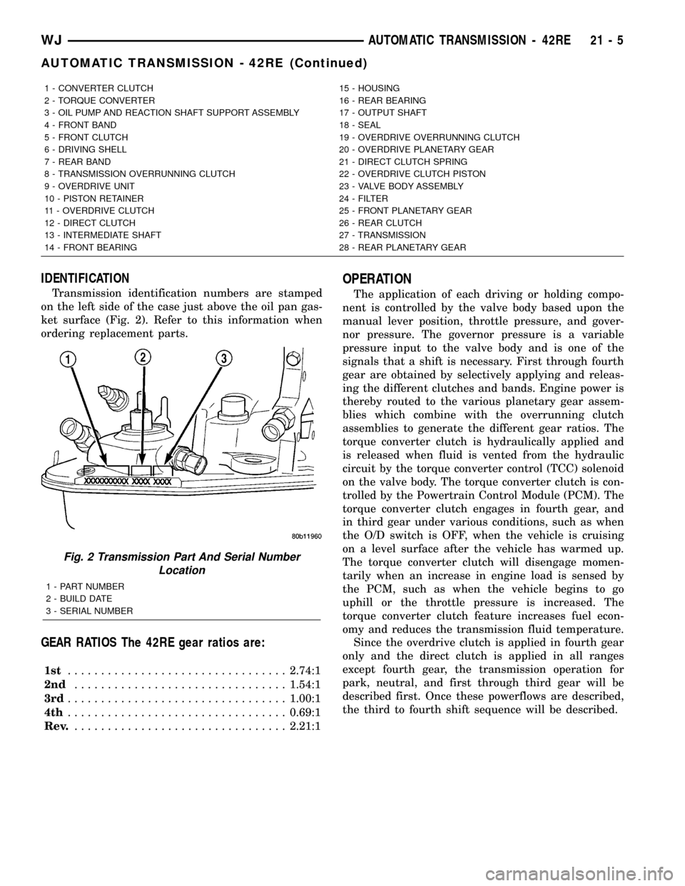
IDENTIFICATION
Transmission identification numbers are stamped
on the left side of the case just above the oil pan gas-
ket surface (Fig. 2). Refer to this information when
ordering replacement parts.
GEAR RATIOS The 42RE gear ratios are:
1st.................................2.74:1
2nd................................1.54:1
3rd.................................1.00:1
4th.................................0.69:1
Rev.................................2.21:1
OPERATION
The application of each driving or holding compo-
nent is controlled by the valve body based upon the
manual lever position, throttle pressure, and gover-
nor pressure. The governor pressure is a variable
pressure input to the valve body and is one of the
signals that a shift is necessary. First through fourth
gear are obtained by selectively applying and releas-
ing the different clutches and bands. Engine power is
thereby routed to the various planetary gear assem-
blies which combine with the overrunning clutch
assemblies to generate the different gear ratios. The
torque converter clutch is hydraulically applied and
is released when fluid is vented from the hydraulic
circuit by the torque converter control (TCC) solenoid
on the valve body. The torque converter clutch is con-
trolled by the Powertrain Control Module (PCM). The
torque converter clutch engages in fourth gear, and
in third gear under various conditions, such as when
the O/D switch is OFF, when the vehicle is cruising
on a level surface after the vehicle has warmed up.
The torque converter clutch will disengage momen-
tarily when an increase in engine load is sensed by
the PCM, such as when the vehicle begins to go
uphill or the throttle pressure is increased. The
torque converter clutch feature increases fuel econ-
omy and reduces the transmission fluid temperature.
Since the overdrive clutch is applied in fourth gear
only and the direct clutch is applied in all ranges
except fourth gear, the transmission operation for
park, neutral, and first through third gear will be
described first. Once these powerflows are described,
the third to fourth shift sequence will be described.
1 - CONVERTER CLUTCH 15 - HOUSING
2 - TORQUE CONVERTER 16 - REAR BEARING
3 - OIL PUMP AND REACTION SHAFT SUPPORT ASSEMBLY 17 - OUTPUT SHAFT
4 - FRONT BAND 18 - SEAL
5 - FRONT CLUTCH 19 - OVERDRIVE OVERRUNNING CLUTCH
6 - DRIVING SHELL 20 - OVERDRIVE PLANETARY GEAR
7 - REAR BAND 21 - DIRECT CLUTCH SPRING
8 - TRANSMISSION OVERRUNNING CLUTCH 22 - OVERDRIVE CLUTCH PISTON
9 - OVERDRIVE UNIT 23 - VALVE BODY ASSEMBLY
10 - PISTON RETAINER 24 - FILTER
11 - OVERDRIVE CLUTCH 25 - FRONT PLANETARY GEAR
12 - DIRECT CLUTCH 26 - REAR CLUTCH
13 - INTERMEDIATE SHAFT 27 - TRANSMISSION
14 - FRONT BEARING 28 - REAR PLANETARY GEAR
Fig. 2 Transmission Part And Serial Number
Location
1 - PART NUMBER
2 - BUILD DATE
3 - SERIAL NUMBER
WJAUTOMATIC TRANSMISSION - 42RE 21 - 5
AUTOMATIC TRANSMISSION - 42RE (Continued)
Page 2190 of 2199

set a temporary fault without turning on the MIL
and continue the leak portion of the test. However,
the PCM will assume that the system is already
pressurized and skip the rapid pump cycles.
Always diagnose leaks, if possible, before discon-
necting connections. Disconnecting connections may
mask a leak condition.
Keep in mind that if the purge solenoid seat is
leaking, it could go undetected since the leak would
end up in the intake manifold. Disconnect the purge
solenoid at the manifold when leak checking. In addi-
tion, a pinched hose fault (P1486) could set if the
purge solenoid does not purge the fuel system prop-
erly (blocked seat). The purge solenoid must vent the
fuel system prior to the LDP system test. If the
purge solenoid cannot properly vent the system the
LDP cannot properly complete the test for P1486 and
this fault can set due to pressure being in the EVAP
system during the test sequence.
Multiple actuation's of the DRB IIItLeak Detec-
tion Pump (LDP) Monitor Test can hide a 0.020 leak
because of excess vapor generation. Additionally, any
source for additional vapor generation can hide a
small leak in the EVAP system. Excess vapor gener-
ation can delay the fall of the LDP diaphragm thus
hiding the small leak. An example of this condition
could be bringing a cold vehicle into a warm shop for
testing or high ambient temperatures.
Fully plugged and partially plugged underhood
vacuum lines have been known to set MIL condi-
tions. P1494 and P0456 can be set for this reason.
Always, thoroughly, check plumbing for pinches or
blockage before condemning components.
TEST EQUIPMENT The Evaporative Emission
Leak Detector (EELD) Miller Special Tool 8404 is
capable of visually detecting leaks in the evaporative
system and will take the place of the ultrasonic leak
detector 6917A. The EELD utilizes shop air and a
smoke generator to visually detect leaks down to
0.020 or smaller. The food grade oil used to make the
smoke includes an UV trace dye that will leave tell-
tale signs of the leak under a black light. This is
helpful when components have to be removed to
determine the exact leak location. For detailed test
instructions, follow the operators manual packaged
with the EELD.
NOTE: Be sure that the PCM has the latest software
update. Reprogram as indicated by any applicable
Technical Service Bulletin. After LDP repairs are
completed, verify the repair by running the DRB IIIT
Leak Detection Pump (LDP) Monitor Test as
described in Technical Service Bulletin 18-12-99.REMOVAL
The Leak Detection Pump (LDP) is located under
the left quarter panel behind the left/rear wheel (Fig.
16). It is attached to a two-piece support bracket
(Fig. 17). The LDP and LDP filter are replaced (ser-
viced) as one unit.
(1) Remove stone shield behind left/rear wheel
(Fig. 18). Drill out plastic rivets for removal.
(2) Remove 3 LDP mounting bolts (Fig. 19).
(3) Remove support bracket brace bolt (Fig. 17).
(4) Loosen, but do not remove 2 support bracket
nuts at frame rail (Fig. 19).
(5) To separate and lower front section of two-piece
support bracket, remove 3 attaching bolts on bottom
of support bracket (Fig. 17). While lowering support
bracket, disconnect LDP wiring clip (Fig. 20).
(6) Disconnect electrical connector at LDP (Fig.
20).
(7) Carefully remove vapor/vacuum lines at LDP
(Fig. 20).
(8) Remove LDP.
INSTALLATION
The LDP is located in the left quarter panel behind
the left/rear wheel. It is attached to a two-piece sup-
port bracket (Fig. 17). The LDP and LDP filter are
replaced (serviced) as one unit.
(1) Position LDP and carefully install vapor/vac-
uum lines to LDP and LDP filter.The vapor/vac-
uum lines and hoses must be firmly connected.
Fig. 16 LOCATION, LDP / EVAP CANISTER
1 - LEAK DETECTION PUMP
2 - EVAP CANISTER
WJEVAPORATIVE EMISSIONS 25 - 35
LEAK DETECTION PUMP (Continued)