Page 1409 of 2199

HEAT SHIELDS
DESCRIPTION
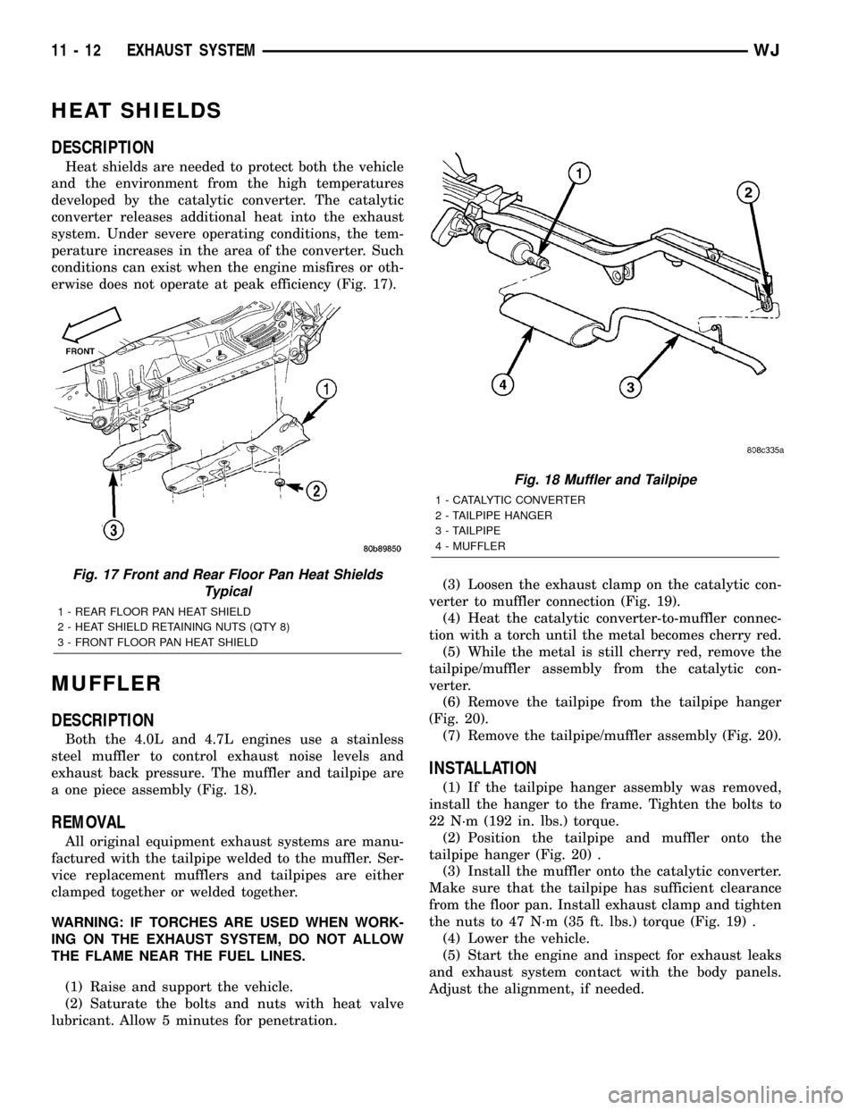
Heat shields are needed to protect both the vehicle
and the environment from the high temperatures
developed by the catalytic converter. The catalytic
converter releases additional heat into the exhaust
system. Under severe operating conditions, the tem-
perature increases in the area of the converter. Such
conditions can exist when the engine misfires or oth-
erwise does not operate at peak efficiency (Fig. 17).
MUFFLER
DESCRIPTION
Both the 4.0L and 4.7L engines use a stainless
steel muffler to control exhaust noise levels and
exhaust back pressure. The muffler and tailpipe are
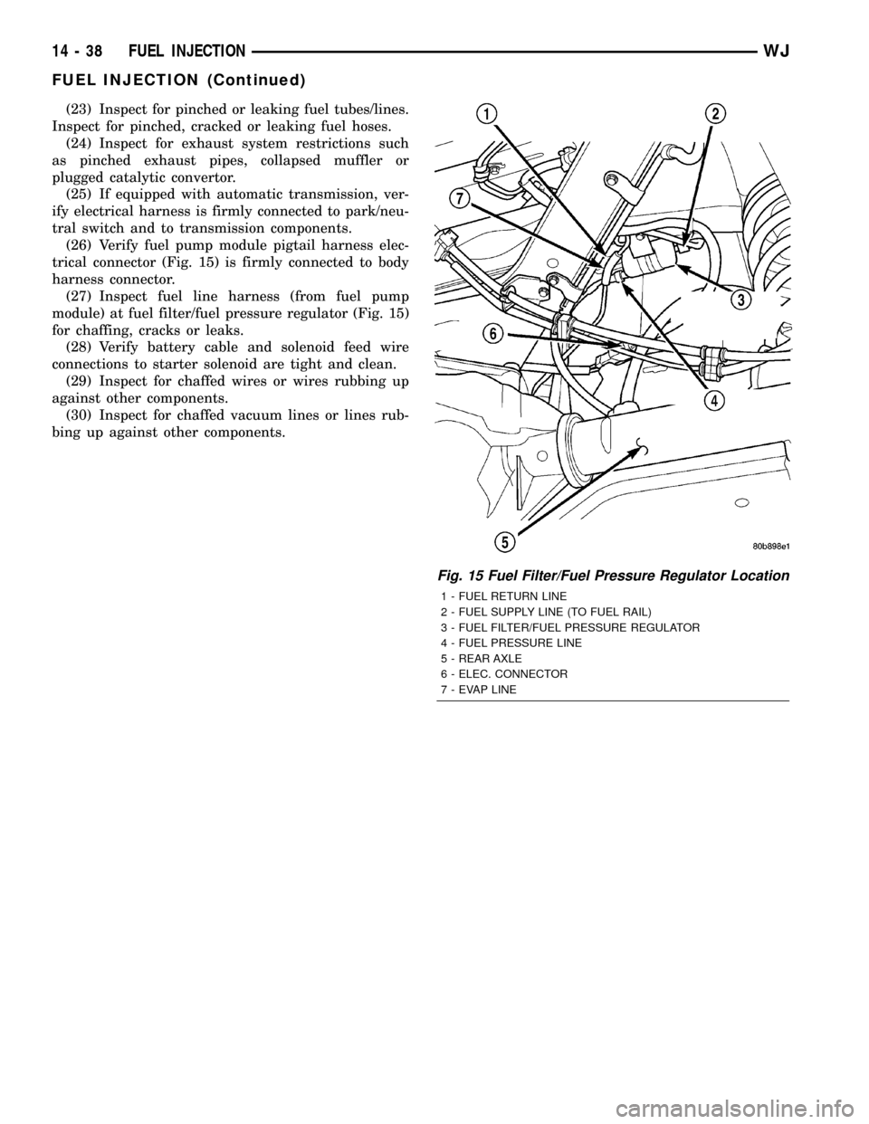
a one piece assembly (Fig. 18).
REMOVAL
All original equipment exhaust systems are manu-
factured with the tailpipe welded to the muffler. Ser-
vice replacement mufflers and tailpipes are either
clamped together or welded together.
WARNING: IF TORCHES ARE USED WHEN WORK-
ING ON THE EXHAUST SYSTEM, DO NOT ALLOW
THE FLAME NEAR THE FUEL LINES.
(1) Raise and support the vehicle.
(2) Saturate the bolts and nuts with heat valve
lubricant. Allow 5 minutes for penetration.(3) Loosen the exhaust clamp on the catalytic con-
verter to muffler connection (Fig. 19).
(4) Heat the catalytic converter-to-muffler connec-
tion with a torch until the metal becomes cherry red.
(5) While the metal is still cherry red, remove the
tailpipe/muffler assembly from the catalytic con-
verter.
(6) Remove the tailpipe from the tailpipe hanger
(Fig. 20).
(7) Remove the tailpipe/muffler assembly (Fig. 20).
INSTALLATION
(1) If the tailpipe hanger assembly was removed,
install the hanger to the frame. Tighten the bolts to
22 N´m (192 in. lbs.) torque.
(2) Position the tailpipe and muffler onto the
tailpipe hanger (Fig. 20) .
(3) Install the muffler onto the catalytic converter.
Make sure that the tailpipe has sufficient clearance
from the floor pan. Install exhaust clamp and tighten
the nuts to 47 N´m (35 ft. lbs.) torque (Fig. 19) .
(4) Lower the vehicle.
(5) Start the engine and inspect for exhaust leaks
and exhaust system contact with the body panels.
Adjust the alignment, if needed.
Fig. 17 Front and Rear Floor Pan Heat Shields
Typical
1 - REAR FLOOR PAN HEAT SHIELD
2 - HEAT SHIELD RETAINING NUTS (QTY 8)
3 - FRONT FLOOR PAN HEAT SHIELD
Fig. 18 Muffler and Tailpipe
1 - CATALYTIC CONVERTER
2 - TAILPIPE HANGER
3 - TAILPIPE
4 - MUFFLER
11 - 12 EXHAUST SYSTEMWJ
Page 1410 of 2199
TAILPIPE
DESCRIPTION
The tailpipe is also made of stainless steel. (Fig.
18) .
OPERATION
The Tailpipe channels the exhaust out of the muf-
fler and out from under the vehicle to control noise
and prevent exhaust gas fumes from entering the
passenger compartment
Fig. 19 Installing Exhaust Clamps
1 - CATALYTIC CONVERTER
2 - MUFFLER
Fig. 20 Muffler and Tailpipe
1 - CATALYTIC CONVERTER
2 - TAILPIPE HANGER
3 - TAILPIPE
4 - MUFFLER
WJEXHAUST SYSTEM 11 - 13
MUFFLER (Continued)
Page 1457 of 2199

(23) Inspect for pinched or leaking fuel tubes/lines.
Inspect for pinched, cracked or leaking fuel hoses.
(24) Inspect for exhaust system restrictions such
as pinched exhaust pipes, collapsed muffler or
plugged catalytic convertor.
(25) If equipped with automatic transmission, ver-
ify electrical harness is firmly connected to park/neu-
tral switch and to transmission components.
(26) Verify fuel pump module pigtail harness elec-
trical connector (Fig. 15) is firmly connected to body
harness connector.
(27) Inspect fuel line harness (from fuel pump
module) at fuel filter/fuel pressure regulator (Fig. 15)
for chaffing, cracks or leaks.
(28) Verify battery cable and solenoid feed wire
connections to starter solenoid are tight and clean.
(29) Inspect for chaffed wires or wires rubbing up
against other components.
(30) Inspect for chaffed vacuum lines or lines rub-
bing up against other components.
Fig. 15 Fuel Filter/Fuel Pressure Regulator Location
1 - FUEL RETURN LINE
2 - FUEL SUPPLY LINE (TO FUEL RAIL)
3 - FUEL FILTER/FUEL PRESSURE REGULATOR
4 - FUEL PRESSURE LINE
5 - REAR AXLE
6 - ELEC. CONNECTOR
7 - EVAP LINE
14 - 38 FUEL INJECTIONWJ
FUEL INJECTION (Continued)