2003 JEEP GRAND CHEROKEE Bolts
[x] Cancel search: BoltsPage 39 of 2199

DIAGNOSIS AND TESTING - REAR
SUSPENSION
CONDITION POSSIBLE CAUSES CORRECTION
VEHICLE INSTABILITY 1. Loose or worn wheel bearings. 1. Replace wheel bearings.
2. Loose, worn or bent suspension
components.2. Inspect, tighten or replace components
as necessary.
3. Tire pressure. 3. Adjust tire pressure.
VEHICLE PULLS TO ONE
SIDE1. Weak or broken spring. 1. Replace spring.
2. Alignment. 2. Align vehicle to specifications.
3.Tires. 3. Replace tires.
4. Brakes. 4. Repair as necassary.
KNOCKING, RATTLING
OR SQUEAKING1. Worn shock bushings. 1. Replace shock.
2. Loose shock mounting. 2. Tighten to specifications.
3. Shock valve. 3. Replace shock.
4. Loose upper ball joint. 4. Replace ball joint.
5. Loose, worn or bent suspension
components.5. Inspect, tighten or replace components
as necessary.
IMPROPER TRACKING 1. Loose, worn or bent suspension
components.1. Inspect, tighten or replace components
as necessary.
2. Bent axle. 2.Replace axle.
SPECIFICATIONS
TORQUE CHART
TORQUE SPECIFICATIONS
DESCRIPTION N´m Ft. Lbs. In. Lbs.
Shock Absorber Upper Nut 108 80 Ð
Shock Absorber Lower Nut 115 85 Ð
Suspension Arm Upper Ball Joint Nut 142 105 Ð
Suspension Arm Upper Frame Bolts 100 74 Ð
Ball Joint Plate Bolts 136 100 Ð
Suspension Arms Lower Axle Bracket Nut 163 120 Ð
Suspension Arms Lower Frame Bracket Nut 156 115 Ð
Stabilizer Bar Retainer Bolts 54 40 Ð
Stabilizer Bar Bar Link Nut 54 40 Ð
Stabilizer Bar Bracket Link Nut 92 68 Ð
2 - 18 REARWJ
REAR (Continued)
Page 42 of 2199

STABILIZER BAR
DESCRIPTION
The stabilizer bar extends across the back side of
the rear axle. Links are connected between the bar
and frame rail brackets. The stabilizer bar and links
are isolated by rubber bushings.
OPERATION
The stabilizer bar is used to control vehicle body
roll, during turns. The bar helps control the vehicle
body in relationship to the suspension.
REMOVAL
(1) Raise and support the vehicle.
(2) Remove the stabilizer bar links from stabilizer
bar and frame mount. (Fig. 7).
(3) Remove the stabilizer bar retainer bolts.
(4) Remove the stabilizer bar.
INSTALLATION
(1) Position the stabilizer bar on the axle and
install the retainers and bolts. Ensure the bar is cen-
tered with equal spacing on both sides. Tighten the
bolts to 54 N´m (40 ft. lbs.).
(2) Install the links to the stabilizer bar and frame
brackets.
(3) Tighten the nuts at the stabilizer bar to 54
N´m (40 ft. lbs.).
(4) Tighten the nuts at the frame brackets to 92
N´m (68 ft. lbs.).
(5) Remove support and lower the vehicle.
UPPER BALL JOINT
DESCRIPTION - UPPER SUSPENSION ARM,
BUSHINGS, AND BALL JOINT
The suspension arm uses vertical spool bushings to
isolate road noise. The suspension arm is bolted
through bushings to cage nuts in the body and a ball
joint plate to the top of the differential housing.
OPERATION - UPPER SUSPENSION ARM,
BUSHINGS, AND BALL JOINT
The upper suspension arm provides fore/aft and
lateral location of the rear axle. The suspension arm
travel is limited through the use of jounce bumpers
in compression and shock absorbers in rebound.
REMOVAL
(1) Raise and support the vehicle.
(2) Support the rear axle with a hydraulic jack.
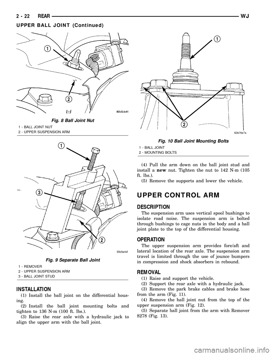
(3) Remove the ball joint nut from the top of the
upper suspension arm (Fig. 8).
(4) Separate ball joint from the arm with Remover
8278 (Fig. 9).
NOTE: It may be necessary to strike the upper con-
trol arm with a hammer to separate the ball joint
from the arm.
(5) Remove the ball joint mounting bolts (Fig.
10)from the differential housing.
(6) Remove the ball joint from the differential
housing.
Fig. 6 Isolator Spring Locator - Typical
1 - LOWER ISOLATOR
2 - SPRING LOCATOR
3 - COIL SPRING
Fig. 7 Rear Stabilizer Bar
1 - LINK
2 - RETAINER
3 - BUSHING
4 - STABILIZER BAR
WJREAR 2 - 21
SPRING (Continued)
Page 43 of 2199

INSTALLATION
(1) Install the ball joint on the differential hous-
ing.
(2) Install the ball joint mounting bolts and
tighten to 136 N´m (100 ft. lbs.).
(3) Raise the rear axle with a hydraulic jack to
align the upper arm with the ball joint.(4) Pull the arm down on the ball joint stud and
install anewnut. Tighten the nut to 142 N´m (105
ft. lbs.).
(5) Remove the supports and lower the vehicle.
UPPER CONTROL ARM
DESCRIPTION
The suspension arm uses vertical spool bushings to
isolate road noise. The suspension arm is bolted
through bushings to cage nuts in the body and a ball
joint plate to the top of the differential housing.
OPERATION
The upper suspension arm provides fore/aft and
lateral location of the rear axle. The suspension arm
travel is limited through the use of jounce bumpers
in compression and shock absorbers in rebound.
REMOVAL
(1) Raise and support the vehicle.
(2) Support the rear axle with a hydraulic jack.
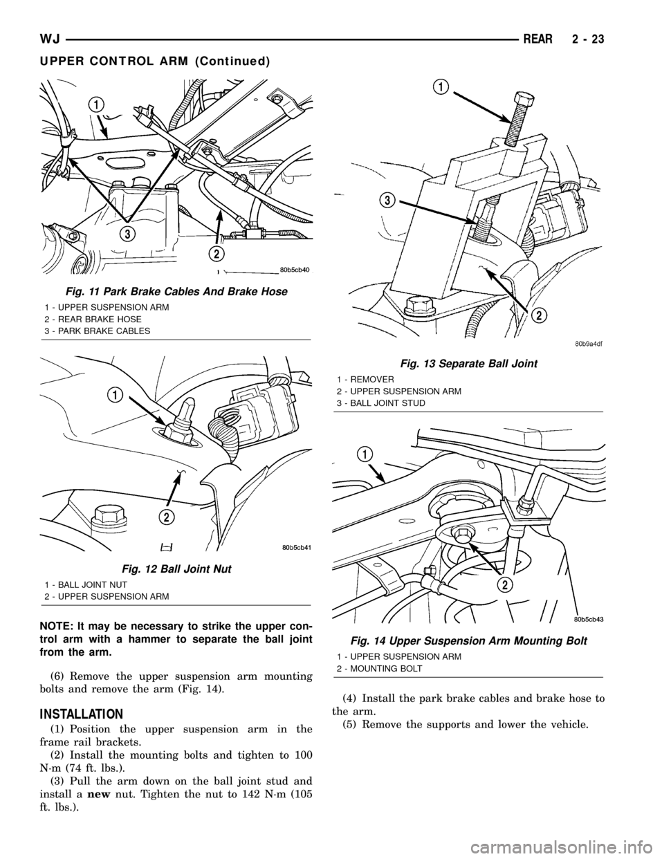
(3) Remove the park brake cables and brake hose
from the arm (Fig. 11).
(4) Remove the ball joint nut from the top of the
upper suspension arm (Fig. 12).
(5) Separate ball joint from the arm with Remover
8278 (Fig. 13).
Fig. 8 Ball Joint Nut
1 - BALL JOINT NUT
2 - UPPER SUSPENSION ARM
Fig. 9 Separate Ball Joint
1 - REMOVER
2 - UPPER SUSPENSION ARM
3 - BALL JOINT STUD
Fig. 10 Ball Joint Mounting Bolts
1 - BALL JOINT
2 - MOUNTING BOLTS
2 - 22 REARWJ
UPPER BALL JOINT (Continued)
Page 44 of 2199

NOTE: It may be necessary to strike the upper con-
trol arm with a hammer to separate the ball joint
from the arm.
(6) Remove the upper suspension arm mounting
bolts and remove the arm (Fig. 14).
INSTALLATION
(1) Position the upper suspension arm in the
frame rail brackets.
(2) Install the mounting bolts and tighten to 100
N´m (74 ft. lbs.).
(3) Pull the arm down on the ball joint stud and
install anewnut. Tighten the nut to 142 N´m (105
ft. lbs.).(4) Install the park brake cables and brake hose to
the arm.
(5) Remove the supports and lower the vehicle.
Fig. 11 Park Brake Cables And Brake Hose
1 - UPPER SUSPENSION ARM
2 - REAR BRAKE HOSE
3 - PARK BRAKE CABLES
Fig. 12 Ball Joint Nut
1 - BALL JOINT NUT
2 - UPPER SUSPENSION ARM
Fig. 13 Separate Ball Joint
1 - REMOVER
2 - UPPER SUSPENSION ARM
3 - BALL JOINT STUD
Fig. 14 Upper Suspension Arm Mounting Bolt
1 - UPPER SUSPENSION ARM
2 - MOUNTING BOLT
WJREAR 2 - 23
UPPER CONTROL ARM (Continued)
Page 47 of 2199

DRIVELINE VIBRATION
Drive Condition Possible Cause Correction
Propeller Shaft Noise 1) Undercoating or other foreign material
on shaft.1) Clean exterior of shaft and wash with
solvent.
2) Loose U-joint clamp screws. 2) Install new clamps and screws and
tighten to proper torque.
3) Loose or bent U-joint yoke or
excessive runout.3) Install new yoke.
4) Incorrect driveline angularity. 4) Measure and correct driveline angles.
5) Rear spring center bolt not in seat. 5) Loosen spring u-bolts and seat center
bolt.
6) Worn U-joint bearings. 6) Install new U-joint.
7) Propeller shaft damaged or out of
balance.7) Installl new propeller shaft.
8) Broken rear spring. 8) Install new rear spring.
9) Excessive runout or unbalanced
condition.9) Re-index propeller shaft, test, and
evaluate.
10) Excessive drive pinion gear shaft
runout.10) Re-index propeller shaft and evaluate.
11) Excessive axle yoke deflection. 11) Inspect and replace yoke if necessary.
12) Excessive transfer case runout. 12) Inspect and repair as necessary.
Universal Joint Noise 1) Loose U-joint clamp screws. 1) Install new clamps and screws and
tighten to proper torque.
2) Lack of lubrication. 2) Replace U-joints as necessary.
BALANCE
NOTE: Removing and re-indexing the propeller
shaft 180É relative to the yoke may eliminate some
vibrations.
If propeller shaft is suspected of being unbalanced,
it can be verified with the following procedure:
(1) Raise the vehicle.
(2) Clean all the foreign material from the propel-
ler shaft and the universal joints.
(3) Inspect the propeller shaft for missing balance
weights, broken welds, and bent areas.If the pro-
peller shaft is bent, it must be replaced.
(4) Inspect the universal joints to ensure that they
are not worn, are properly installed, and are cor-
rectly aligned with the shaft.
(5) Check the universal joint clamp screws torque.
(6) Remove the wheels and tires. Install the wheel
lug nuts to retain the brake drums or rotors.
(7) Mark and number the shaft six inches from the
yoke end at four positions 90É apart.
(8) Run and accelerate the vehicle until vibration
occurs. Note the intensity and speed the vibration
occurred. Stop the engine.(9) Install a screw clamp at position 1 (Fig. 1).
Fig. 1 CLAMP SCREW - POSITION 1
1 - CLAMP
2 - SCREWDRIVER
3 - 2 PROPELLER SHAFTWJ
PROPELLER SHAFT (Continued)
Page 50 of 2199

SPECIFICATIONS
TORQUE SPECIFICATIONS
DESCRIPTION N´m Ft. Lbs. In. Lbs.
Front Shaft - Companion Flange Bolts 32 24 -
4.7L Front Shaft - Axle Yoke Nuts 19 14 -
4.7L Front Shaft - Transfer Case Bolts 27 20 -
Rear Shaft - Yoke Nuts 19 14 -
SPECIAL TOOLS
Fig. 7 U-JOINT ANGLE EXAMPLE
1 - 4.9É Angle (C)
2 - 3.2É Angle (B)
3 - Input Yoke4 - 3.0É Angle (A)
5 - Output Yoke
Inclinometer 7663
WJPROPELLER SHAFT 3 - 5
PROPELLER SHAFT (Continued)
Page 51 of 2199

PROPELLER SHAFT - FRONT
REMOVAL
NOTE: Different length propeller shafts are used for
different drivetrain applications. Ensure that the
correct propeller shaft is used.
(1) Place vehicle on floor or drive-on hoist with full
weight of vehicle on suspension.
(2) Shift the transmission and transfer case, if nec-
essary, into the Neutral position.
(3) Measure the distance from the face of the C/V
joint cup to the end of the C/V joint boot (Fig. 8).
(4) The correct length is 142.7 mm (5.61 in.).
NOTE: If the measurement is not correct, the wrong
shaft may have been installed or a mating compo-
nent (front axle or transfer case) may be installed
incorrectly. Investigate and correct as necessary.
(5) Mark a line across the companion flange at the
transfer case and C/V joint at the rear of the front
propeller shaft for installation reference.
(6) Mark a line across the C/V joints and the pin-
ion companion flanges for installation reference.
(7) Remove bolts from the front C/V joint to the
pinion companion flange.
(8) Remove bolts from the rear C/V joint to the
transfer case companion flange.
(9) Push the propeller shaft forward to clear trans-
fer case companion flange and remove the shaft.
INSTALLATION
NOTE: Different length propeller shafts are used for
different drivetrain applications. Ensure that the
correct propeller shaft is used.
(1) Install the shaft between companion flanges.
(2) The shaft should rotate freely in the pinion
flange.
(3) Align marks on the companion flanges with the
marks on the C/V joints.
(4) Install bolts to the front C/V joint and tighten
bolts to 32 N´m (24 ft. lbs.).
(5) Install the bolts to the rear C/V joint and
tighten bolts to 32 N´m (24 ft. lbs.).
(6) Verify propeller shaft length.
(7) Lower vehicle.
PROPELLER SHAFT - FRONT
4.7L
REMOVAL
(1) Raise and support vehicle.
(2) Remove crossmember/skid plate as necessary to
gain access to the propeller shaft.
(3) Shift transmission and transfer case, if neces-
sary into Neutral.
(4) Mark a line across the yoke at the transfer
case, link yoke and propeller shaft yoke at the rear of
the front propeller shaft for installation reference
(Fig. 9).
(5) Mark a line across the propeller shaft yoke and
pinion shaft yoke for installation reference.
Fig. 8 MEASUREMENT
1 - C/V JOINT CUP
2 - C/V BOOT END
3 - MEASUREMENT
Fig. 9 REFERENCE MARKS ON YOKES
1 - REFERENCE MARKS
3 - 6 PROPELLER SHAFTWJ
Page 52 of 2199

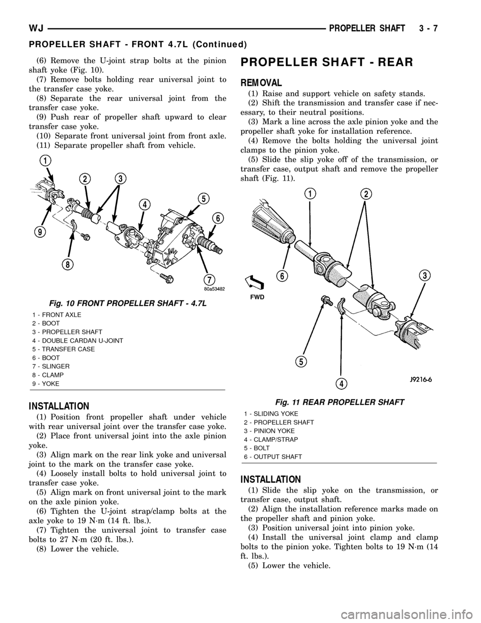
(6) Remove the U-joint strap bolts at the pinion
shaft yoke (Fig. 10).
(7) Remove bolts holding rear universal joint to
the transfer case yoke.
(8) Separate the rear universal joint from the
transfer case yoke.
(9) Push rear of propeller shaft upward to clear
transfer case yoke.
(10) Separate front universal joint from front axle.
(11) Separate propeller shaft from vehicle.
INSTALLATION
(1) Position front propeller shaft under vehicle
with rear universal joint over the transfer case yoke.
(2) Place front universal joint into the axle pinion
yoke.
(3) Align mark on the rear link yoke and universal
joint to the mark on the transfer case yoke.
(4) Loosely install bolts to hold universal joint to
transfer case yoke.
(5) Align mark on front universal joint to the mark
on the axle pinion yoke.
(6) Tighten the U-joint strap/clamp bolts at the
axle yoke to 19 N´m (14 ft. lbs.).
(7) Tighten the universal joint to transfer case
bolts to 27 N´m (20 ft. lbs.).
(8) Lower the vehicle.
PROPELLER SHAFT - REAR
REMOVAL
(1) Raise and support vehicle on safety stands.
(2) Shift the transmission and transfer case if nec-
essary, to their neutral positions.
(3) Mark a line across the axle pinion yoke and the
propeller shaft yoke for installation reference.
(4) Remove the bolts holding the universal joint
clamps to the pinion yoke.
(5) Slide the slip yoke off of the transmission, or
transfer case, output shaft and remove the propeller
shaft (Fig. 11).
INSTALLATION
(1) Slide the slip yoke on the transmission, or
transfer case, output shaft.
(2) Align the installation reference marks made on
the propeller shaft and pinion yoke.
(3) Position universal joint into pinion yoke.
(4) Install the universal joint clamp and clamp
bolts to the pinion yoke. Tighten bolts to 19 N´m (14
ft. lbs.).
(5) Lower the vehicle.
Fig. 10 FRONT PROPELLER SHAFT - 4.7L
1 - FRONT AXLE
2 - BOOT
3 - PROPELLER SHAFT
4 - DOUBLE CARDAN U-JOINT
5 - TRANSFER CASE
6 - BOOT
7 - SLINGER
8 - CLAMP
9 - YOKE
Fig. 11 REAR PROPELLER SHAFT
1 - SLIDING YOKE
2 - PROPELLER SHAFT
3 - PINION YOKE
4 - CLAMP/STRAP
5 - BOLT
6 - OUTPUT SHAFT
WJPROPELLER SHAFT 3 - 7
PROPELLER SHAFT - FRONT 4.7L (Continued)