2003 JEEP GRAND CHEROKEE Failure
[x] Cancel search: FailurePage 1484 of 2199

COLUMN
TABLE OF CONTENTS
page page
COLUMN
DESCRIPTION
SERVICE WARNINGS AND CAUTIONS......7
REMOVAL.............................8
INSTALLATION.........................11
SPECIFICATIONS
TORQUE CHART......................12
SPECIAL TOOLS
STEERING COLUMN...................12
IGNITION SWITCH
DESCRIPTION.........................12
DIAGNOSIS AND TESTING - IGNITION
SWITCH............................12
REMOVAL
IGNITION SWITCH REMOVAL............13INSTALLATION
IGNITION SWITCH INSTALLATION........13
KEY-IN IGNITION SWITCH
DESCRIPTION.........................14
OPERATION...........................14
DIAGNOSIS AND TESTING
KEY-IN IGNITION SWITCH..............14
LOCK CYLINDER
REMOVAL.............................14
INSTALLATION.........................15
STEERING WHEEL
REMOVAL.............................15
INSTALLATION.........................15
COLUMN
DESCRIPTION
SERVICE WARNINGS AND CAUTIONS
DESCRIPTION
The tilt column (Fig. 1) has been designed to be
serviced as an assembly, less the wiring, switches,
shrouds, steering wheel, etc. Most steering column
components can be serviced without removing the
steering column from the vehicle.To service the steering wheel, switches or air-
bag,(Refer to 8 - ELECTRICAL/RESTRAINTS -
WARNING).
WARNING: THE AIRBAG SYSTEM IS A SENSITIVE,
COMPLEX ELECTRO-MECHANICAL UNIT. BEFORE
ATTEMPTING TO DIAGNOSE, REMOVE OR INSTALL
THE AIRBAG SYSTEM COMPONENTS YOU MUST
FIRST DISCONNECT AND ISOLATE THE BATTERY
NEGATIVE (GROUND) CABLE. THEN WAIT TWO
MINUTES FOR THE SYSTEM CAPACITOR TO DIS-
CHARGE. FAILURE TO DO SO COULD RESULT IN
ACCIDENTAL DEPLOYMENT OF THE AIRBAG AND
POSSIBLE PERSONAL INJURY. THE FASTENERS,
SCREWS, AND BOLTS, ORIGINALLY USED FOR
THE AIRBAG COMPONENTS, HAVE SPECIAL COAT-
INGS AND ARE SPECIFICALLY DESIGNED FOR THE
AIRBAG SYSTEM. THEY MUST NEVER BE
REPLACED WITH ANY SUBSTITUTES. ANYTIME A
NEW FASTENER IS NEEDED, REPLACE WITH THE
CORRECT FASTENERS PROVIDED IN THE SERVICE
PACKAGE OR FASTENERS LISTED IN THE PARTS
BOOKS.
CAUTION: Safety goggles should be worn at all
times when working on steering columns.
Fig. 1 Steering Column
WJCOLUMN 19 - 7
Page 1485 of 2199

REMOVAL
WARNING: BEFORE SERVICING THE STEERING
COLUMN THE AIRBAG SYSTEM MUST BE DIS-
ARMED. FAILURE TO DO SO MAY RESULT IN ACCI-
DENTAL DEPLOYMENT OF THE AIRBAG AND
POSSIBLE PERSONAL INJURY.(Refer to 8 - ELEC-
TRICAL/RESTRAINTS/DRIVER AIRBAG - REMOVAL).
(1) Position front wheels straight ahead.
(2) Disconnect and isolate the negative (ground)
cable from the battery.
(3) Remove the airbag,(Refer to 8 - ELECTRICAL/
RESTRAINTS/DRIVER AIRBAG - REMOVAL).
(4) Remove the steering wheel nut and remove
wheel with Puller C-3894-A (Fig. 2).
NOTE: Ensure the puller jaws are seated in the
pockets (Fig. 3) of the steering wheel armature.(5) Remove the cluster bezel by pulling it from the
instrument panel (Fig. 4).
Fig. 2 Steering Wheel Puller
1 - PULLER
2 - STEERING WHEEL
Fig. 3 Steering Wheel Pockets
1 - STEERING WHEEL POCKETS
Fig. 4 Cluster Bezel
1 - CLUSTER
2 - CLUSTER BEZEL
3 - STEERING COLUMN
4 - KNEE BLOCKER COVER
19 - 8 COLUMNWJ
COLUMN (Continued)
Page 1488 of 2199

(13) Remove the column coupler bolt (Fig. 13) and
slide the coupler off the column shaft.
(14) Remove the column mounting nuts (Fig. 13)
and lower column off mounting studs. Remove the
column from the vehicle.
(15) Remove the ignition switch, cylinder and
SKIM, (Refer to 19 - STEERING/COLUMN/LOCK
CYLINDER HOUSING - REMOVAL). (Fig. 14).INSTALLATION
WARNING: BEFORE SERVICING THE STEERING COL-
UMN THE AIRBAG SYSTEM MUST BE DISARMED.
FAILURE TO DO SO MAY RESULT IN ACCIDENTAL
DEPLOYMENT OF THE AIRBAG AND POSSIBLE PER-
SONAL INJURY. (Refer to 8 - ELECTRICAL/RE-
STRAINTS/DRIVER AIRBAG - INSTALLATION).
(1) Install the ignition switch, cylinder and SKIM-
,(Refer to 19 - STEERING/COLUMN/IGNITION
SWITCH - INSTALLATION).
(2) Install the column into the vehicle and lift the
column up onto the mounting studs. Install the
mounting nuts and tighten to 12 N´m (105 in. lbs.).
(3) Slid the coupler onto the column shaft and
install the coupler bolt. Tighten the coupler bolt to 49
N´m (36 ft. lbs.).
(4) Turn the ignition key to the on position then
release and install the shifter interlock cable (Fig.
12) into ignition lock cylinder housing.
(5) Verify ignition switch and shifter interlock
operation.,(Refer to 21 - TRANSMISSION/TRANS-
AXLE/AUTOMATIC - 42RE/GEAR SHIFT CABLE -
ADJUSTMENTS).
(6) Slide the multifuction switch and clock spring
onto the column as an assembly (Fig. 11).
(7) Install the multifuction switch mounting screw
(Fig. 10).
(8) Connect the multifuction switch (Fig. 9) and
ignition switch harness.
(9) Install the upper fixed shroud and mounting
screws (Fig. 8).
(10) Install the lower steering column shroud to
the steering column. Install and tighten the mount-
ing screw.
(11) Install the upper column shroud. Align the
upper shroud to the lower shroud and snap the two
shroud halves together.
(12) Install the knee blocker cover (Fig. 5),(Refer
to 23 - BODY/INSTRUMENT PANEL - INSTALLA-
TION).
(13) Install the cluster bezel by inserting it into
the instrument panel (Fig. 4).
(14) Align the steering wheel with the column
index spline and install the wheel on the column
shaft. Pull the clockspring wire harness through the
steering wheel armature spokes.
(15) Install and tighten the steering wheel mount-
ing nut to 61 N´m (45 ft. lbs.).
(16) Connect the steering wheel wire harness con-
nector to the clock spring connector.
(17) Install the airbag,(Refer to 8 - ELECTRICAL/
RESTRAINTS/DRIVER AIRBAG - INSTALLATION).
(18) Connect the negative (ground) cable to the
battery.
Fig. 13 Column Coupler Bolt And Mounting Nuts
1 - COLUMN MOUNTING NUTS
2 - COUPLER BOLT
Fig. 14 Ignition Switch And SKIM
1 - SKIM
2 - IGNITION SWITCH
WJCOLUMN 19 - 11
COLUMN (Continued)
Page 1491 of 2199

KEY-IN IGNITION SWITCH
DESCRIPTION
The key-in ignition switch is concealed within and
integral to the ignition switch, which is mounted on
the steering column. The key-in ignition switch is
actuated by the ignition lock cylinder mechanism,
and is hard wired between a body ground and the
Body Control Module (BCM) through the instrument
panel wire harness.
The key-in ignition switch cannot be adjusted or
repaired and, if faulty or damaged, the entire igni-
tion switch unit must be replaced,(Refer to 19 -
STEERING/COLUMN/LOCK CYLINDER HOUSING
- REMOVAL). For complete circuit diagrams, refer to
Body Control Modulein the Contents of Wiring
Diagrams.
OPERATION
The key-in ignition switch closes a path to ground
for the BCM when the ignition key is inserted in the
ignition lock cylinder, and opens the ground path
when the key is removed from the ignition lock cyl-
inder. The BCM monitors the key-in ignition switch
status through an internal pull-up, then sends the
proper switch status messages to other electronic
modules over the Programmable Communications
Interface (PCI) data bus network. The key-in ignition
switch status is also used by the BCM as an input
for chime warning system operation.
DIAGNOSIS AND TESTING
KEY-IN IGNITION SWITCH
For complete circuit diagrams, refer toBody Con-
trol Modulein the Contents of Wiring Diagrams.
WARNING: ON VEHICLES EQUIPPED WITH AIR-
BAGS, REFER TO GROUP 8M - PASSIVE
RESTRAINT SYSTEMS BEFORE ATTEMPTING ANY
STEERING WHEEL, STEERING COLUMN, OR
INSTRUMENT PANEL COMPONENT DIAGNOSIS OR
SERVICE. FAILURE TO TAKE THE PROPER PRE-
CAUTIONS COULD RESULT IN ACCIDENTAL AIR-
BAG DEPLOYMENT AND POSSIBLE PERSONAL
INJURY.(1) Disconnect and isolate the battery negative
cable. Disconnect the instrument panel wire harness
connector from the key-in ignition switch connector
receptacle on the ignition switch. Check for continu-
ity between the key-in ignition switch sense and
ground terminals of the key-in ignition switch con-
nector receptacle. There should be continuity with
the key inserted in the ignition lock cylinder, and no
continuity with the key removed from the ignition
lock cylinder. If OK, go to Step 2. If not OK, replace
the faulty ignition switch unit.
(2) Check for continuity between the ground cir-
cuit cavity of the instrument panel wire harness con-
nector for the key-in ignition switch and a good
ground. There should be continuity. If OK, go to Step
3. If not OK, repair the open ground circuit to ground
as required.
(3) Disconnect the gray 26-way instrument panel
wire harness connector from the Body Control Mod-
ule (BCM) connector receptacle. Check for continuity
between the key-in ignition switch sense circuit cav-
ity of the instrument panel wire harness connector
for the key-in ignition switch and a good ground.
There should be no continuity. If OK, go to Step 4. If
not OK, repair the shorted key-in ignition switch
sense circuit as required.
(4) Check for continuity between the key-in igni-
tion switch sense circuit cavities of the instrument
panel wire harness connector for the key-in ignition
switch and the gray 26-way instrument panel wire
harness connector for the BCM. There should be con-
tinuity. If OK, use a DRB scan tool and the proper
Diagnostic Procedures manual to test the BCM. If
not OK, repair the open key-in ignition switch sense
circuit as required.
LOCK CYLINDER
REMOVAL
The ignition key must be in the key cylinder for
cylinder removal. The key cylinder must be removed
first before removing ignition switch.
(1) Disconnect negative battery cable at battery.
(2) If equipped with an automatic transmission,
place shifter in PARK position.
(3) Rotate key to ON position.
19 - 14 COLUMNWJ
Page 1536 of 2199

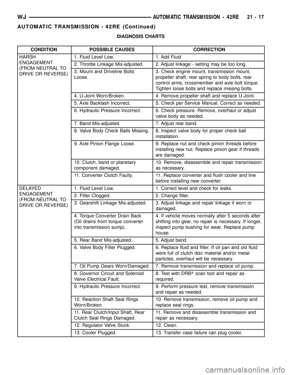
DIAGNOSIS CHARTS
CONDITION POSSIBLE CAUSES CORRECTION
HARSH
ENGAGEMENT
(FROM NEUTRAL TO
DRIVE OR REVERSE)1. Fluid Level Low. 1. Add Fluid
2. Throttle Linkage Mis-adjusted. 2. Adjust linkage - setting may be too long.
3. Mount and Driveline Bolts
Loose.3. Check engine mount, transmission mount,
propeller shaft, rear spring to body bolts, rear
control arms, crossmember and axle bolt torque.
Tighten loose bolts and replace missing bolts.
4. U-Joint Worn/Broken. 4. Remove propeller shaft and replace U-Joint.
5. Axle Backlash Incorrect. 5. Check per Service Manual. Correct as needed.
6. Hydraulic Pressure Incorrect. 6. Check pressure. Remove, overhaul or adjust
valve body as needed.
7. Band Mis-adjusted. 7. Adjust rear band.
8. Valve Body Check Balls Missing. 8. Inspect valve body for proper check ball
installation.
9. Axle Pinion Flange Loose. 9. Replace nut and check pinion threads before
installing new nut. Replace pinion gear if threads
are damaged.
10. Clutch, band or planetary
component damaged.10. Remove, disassemble and repair transmission
as necessary.
11. Converter Clutch Faulty. 11. Replace converter and flush cooler and line
before installing new converter.
DELAYED
ENGAGEMENT
(FROM NEUTRAL TO
DRIVE OR REVERSE)1. Fluid Level Low. 1. Correct level and check for leaks.
2. Filter Clogged. 2. Change filter.
3. Gearshift Linkage Mis-adjusted. 3. Adjust linkage and repair linkage if worn or
damaged.
4. Torque Converter Drain Back
(Oil drains from torque converter
into transmission sump).4. If vehicle moves normally after 5 seconds after
shifting into gear, no repair is necessary. If longer,
inspect pump bushing for wear. Replace pump
house.
5. Rear Band Mis-adjusted. 5. Adjust band.
6. Valve Body Filter Plugged. 6. Replace fluid and filter. If oil pan and old fluid
were full of clutch disc material and/or metal
particles, overhaul will be necessary.
7. Oil Pump Gears Worn/Damaged. 7. Remove transmission and replace oil pump.
8. Governor Circuit and Solenoid
Valve Electrical Fault.8. Test with DRBTscan tool and repair as
required.
9. Hydraulic Pressure Incorrect. 9. Perform pressure test, remove transmission
and repair as needed.
10. Reaction Shaft Seal Rings
Worn/Broken.10. Remove transmission, remove oil pump and
replace seal rings.
11. Rear Clutch/Input Shaft, Rear
Clutch Seal Rings Damaged.11. Remove and disassemble transmission and
repair as necessary.
12. Regulator Valve Stuck. 12. Clean.
13. Cooler Plugged. 13. Transfer case failure can plug cooler.
WJAUTOMATIC TRANSMISSION - 42RE 21 - 17
AUTOMATIC TRANSMISSION - 42RE (Continued)
Page 1538 of 2199

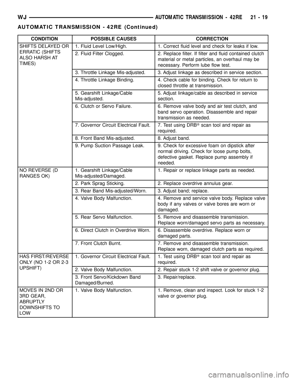
CONDITION POSSIBLE CAUSES CORRECTION
SHIFTS DELAYED OR
ERRATIC (SHIFTS
ALSO HARSH AT
TIMES)1. Fluid Level Low/High. 1. Correct fluid level and check for leaks if low.
2. Fluid Filter Clogged. 2. Replace filter. If filter and fluid contained clutch
material or metal particles, an overhaul may be
necessary. Perform lube flow test.
3. Throttle Linkage Mis-adjusted. 3. Adjust linkage as described in service section.
4. Throttle Linkage Binding. 4. Check cable for binding. Check for return to
closed throttle at transmission.
5. Gearshift Linkage/Cable
Mis-adjusted.5. Adjust linkage/cable as described in service
section.
6. Clutch or Servo Failure. 6. Remove valve body and air test clutch, and
band servo operation. Disassemble and repair
transmission as needed.
7. Governor Circuit Electrical Fault. 7. Test using DRBTscan tool and repair as
required.
8. Front Band Mis-adjusted. 8. Adjust band.
9. Pump Suction Passage Leak. 9. Check for excessive foam on dipstick after
normal driving. Check for loose pump bolts,
defective gasket. Replace pump assembly if
needed.
NO REVERSE (D
RANGES OK)1. Gearshift Linkage/Cable
Mis-adjusted/Damaged.1. Repair or replace linkage parts as needed.
2. Park Sprag Sticking. 2. Replace overdrive annulus gear.
3. Rear Band Mis-adjusted/Worn. 3. Adjust band; replace.
4. Valve Body Malfunction. 4. Remove and service valve body. Replace valve
body if any valves or valve bores are worn or
damaged.
5. Rear Servo Malfunction. 5. Remove and disassemble transmission.
Replace worn/damaged servo parts as necessary.
6. Direct Clutch in Overdrive Worn. 6. Disassemble overdrive. Replace worn or
damaged parts.
7. Front Clutch Burnt. 7. Remove and disassemble transmission.
Replace worn, damaged clutch parts as required.
HAS FIRST/REVERSE
ONLY (NO 1-2 OR 2-3
UPSHIFT)1. Governor Circuit Electrical Fault. 1. Test using DRBTscan tool and repair as
required.
2. Valve Body Malfunction. 2. Repair stuck 1-2 shift valve or governor plug.
3. Front Servo/Kickdown Band
Damaged/Burned.3. Repair/replace.
MOVES IN 2ND OR
3RD GEAR,
ABRUPTLY
DOWNSHIFTS TO
LOW1. Valve Body Malfunction. 1. Remove, clean and inspect. Look for stuck 1-2
valve or governor plug.
WJAUTOMATIC TRANSMISSION - 42RE 21 - 19
AUTOMATIC TRANSMISSION - 42RE (Continued)
Page 1542 of 2199

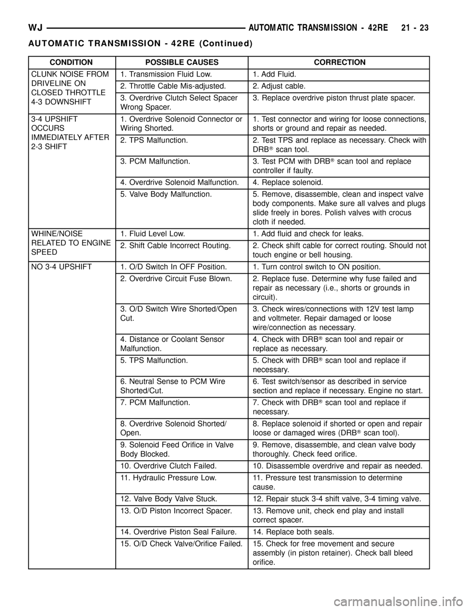
CONDITION POSSIBLE CAUSES CORRECTION
CLUNK NOISE FROM
DRIVELINE ON
CLOSED THROTTLE
4-3 DOWNSHIFT1. Transmission Fluid Low. 1. Add Fluid.
2. Throttle Cable Mis-adjusted. 2. Adjust cable.
3. Overdrive Clutch Select Spacer
Wrong Spacer.3. Replace overdrive piston thrust plate spacer.
3-4 UPSHIFT
OCCURS
IMMEDIATELY AFTER
2-3 SHIFT1. Overdrive Solenoid Connector or
Wiring Shorted.1.
Test connector and wiring for loose connections,
shorts or ground and repair as needed.
2. TPS Malfunction. 2. Test TPS and replace as necessary. Check with
DRBTscan tool.
3. PCM Malfunction. 3. Test PCM with DRBTscan tool and replace
controller if faulty.
4. Overdrive Solenoid Malfunction. 4. Replace solenoid.
5. Valve Body Malfunction. 5. Remove, disassemble, clean and inspect valve
body components. Make sure all valves and plugs
slide freely in bores. Polish valves with crocus
cloth if needed.
WHINE/NOISE
RELATED TO ENGINE
SPEED1. Fluid Level Low. 1. Add fluid and check for leaks.
2. Shift Cable Incorrect Routing. 2. Check shift cable for correct routing. Should not
touch engine or bell housing.
NO 3-4 UPSHIFT 1. O/D Switch In OFF Position. 1. Turn control switch to ON position.
2. Overdrive Circuit Fuse Blown. 2. Replace fuse. Determine why fuse failed and
repair as necessary (i.e., shorts or grounds in
circuit).
3. O/D Switch Wire Shorted/Open
Cut.3. Check wires/connections with 12V test lamp
and voltmeter. Repair damaged or loose
wire/connection as necessary.
4. Distance or Coolant Sensor
Malfunction.4. Check with DRBTscan tool and repair or
replace as necessary.
5. TPS Malfunction. 5. Check with DRBTscan tool and replace if
necessary.
6. Neutral Sense to PCM Wire
Shorted/Cut.6. Test switch/sensor as described in service
section and replace if necessary. Engine no start.
7. PCM Malfunction. 7. Check with DRBTscan tool and replace if
necessary.
8. Overdrive Solenoid Shorted/
Open.8. Replace solenoid if shorted or open and repair
loose or damaged wires (DRBTscan tool).
9. Solenoid Feed Orifice in Valve
Body Blocked.9. Remove, disassemble, and clean valve body
thoroughly. Check feed orifice.
10. Overdrive Clutch Failed. 10. Disassemble overdrive and repair as needed.
11. Hydraulic Pressure Low. 11. Pressure test transmission to determine
cause.
12. Valve Body Valve Stuck. 12. Repair stuck 3-4 shift valve, 3-4 timing valve.
13. O/D Piston Incorrect Spacer. 13. Remove unit, check end play and install
correct spacer.
14. Overdrive Piston Seal Failure. 14. Replace both seals.
15. O/D Check Valve/Orifice Failed. 15. Check for free movement and secure
assembly (in piston retainer). Check ball bleed
orifice.
WJAUTOMATIC TRANSMISSION - 42RE 21 - 23
AUTOMATIC TRANSMISSION - 42RE (Continued)
Page 1543 of 2199

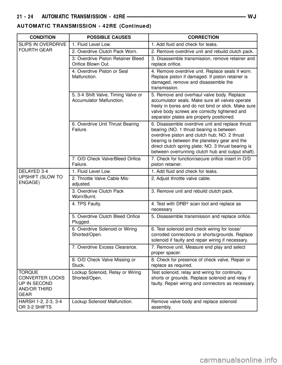
CONDITION POSSIBLE CAUSES CORRECTION
SLIPS IN OVERDRIVE
FOURTH GEAR1. Fluid Level Low. 1. Add fluid and check for leaks.
2. Overdrive Clutch Pack Worn. 2. Remove overdrive unit and rebuild clutch pack.
3. Overdrive Piston Retainer Bleed
Orifice Blown Out.3. Disassemble transmission, remove retainer and
replace orifice.
4. Overdrive Piston or Seal
Malfunction.4. Remove overdrive unit. Replace seals if worn.
Replace piston if damaged. If piston retainer is
damaged, remove and disassemble the
transmission.
5. 3-4 Shift Valve, Timing Valve or
Accumulator Malfunction.5. Remove and overhaul valve body. Replace
accumulator seals. Make sure all valves operate
freely in bores and do not bind or stick. Make sure
valve body screws are correctly tightened and
separator plates are properly positioned.
6. Overdrive Unit Thrust Bearing
Failure.6. Disassemble overdrive unit and replace thrust
bearing (NO. 1 thrust bearing is between
overdrive piston and clutch hub; NO. 2 thrust
bearing is between the planetary gear and the
direct clutch spring plate; NO. 3 thrust bearing is
between overrunning clutch hub and output shaft).
7. O/D Check Valve/Bleed Orifice
Failure.7. Check for function/secure orifice insert in O/D
piston retainer.
DELAYED 3-4
UPSHIFT (SLOW TO
ENGAGE)1. Fluid Level Low. 1. Add fluid and check for leaks.
2. Throttle Valve Cable Mis-
adjusted.2. Adjust throttle valve cable.
3. Overdrive Clutch Pack
Worn/Burnt.3. Remove unit and rebuild clutch pack.
4. TPS Faulty. 4. Test with DRBTscan tool and replace as
necessary
5. Overdrive Clutch Bleed Orifice
Plugged.5. Disassemble transmission and replace orifice.
6. Overdrive Solenoid or Wiring
Shorted/Open.6. Test solenoid and check wiring for loose/
corroded connections or shorts/grounds. Replace
solenoid if faulty and repair wiring if necessary.
7. Overdrive Excess Clearance. 7. Remove unit. Measure end play and select
proper spacer.
8. O/D Check Valve Missing or
Stuck.8. Check for presence of check valve. Repair or
replace as required.
TORQUE
CONVERTER LOCKS
UP IN SECOND
AND/OR THIRD
GEARLockup Solenoid, Relay or Wiring
Shorted/Open.Test solenoid, relay and wiring for continuity,
shorts or grounds. Replace solenoid and relay if
faulty. Repair wiring and connectors as necessary.
HARSH 1-2, 2-3, 3-4
OR 3-2 SHIFTSLockup Solenoid Malfunction. Remove valve body and replace solenoid
assembly.
21 - 24 AUTOMATIC TRANSMISSION - 42REWJ
AUTOMATIC TRANSMISSION - 42RE (Continued)