2003 JEEP GRAND CHEROKEE crankshaft
[x] Cancel search: crankshaftPage 1739 of 2199

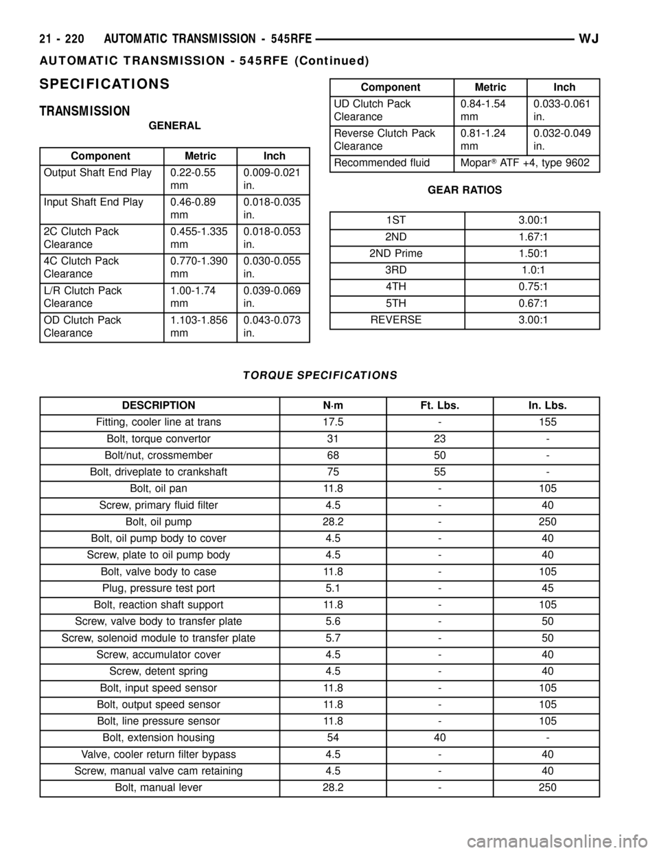
SPECIFICATIONS
TRANSMISSION
GENERAL
Component Metric Inch
Output Shaft End Play 0.22-0.55
mm0.009-0.021
in.
Input Shaft End Play 0.46-0.89
mm0.018-0.035
in.
2C Clutch Pack
Clearance0.455-1.335
mm0.018-0.053
in.
4C Clutch Pack
Clearance0.770-1.390
mm0.030-0.055
in.
L/R Clutch Pack
Clearance1.00-1.74
mm0.039-0.069
in.
OD Clutch Pack
Clearance1.103-1.856
mm0.043-0.073
in.
Component Metric Inch
UD Clutch Pack
Clearance0.84-1.54
mm0.033-0.061
in.
Reverse Clutch Pack
Clearance0.81-1.24
mm0.032-0.049
in.
Recommended fluid MoparTATF +4, type 9602
GEAR RATIOS
1ST 3.00:1
2ND 1.67:1
2ND Prime 1.50:1
3RD 1.0:1
4TH 0.75:1
5TH 0.67:1
REVERSE 3.00:1
TORQUE SPECIFICATIONS
DESCRIPTION N´m Ft. Lbs. In. Lbs.
Fitting, cooler line at trans 17.5 - 155
Bolt, torque convertor 31 23 -
Bolt/nut, crossmember 68 50 -
Bolt, driveplate to crankshaft 75 55 -
Bolt, oil pan 11.8 - 105
Screw, primary fluid filter 4.5 - 40
Bolt, oil pump 28.2 - 250
Bolt, oil pump body to cover 4.5 - 40
Screw, plate to oil pump body 4.5 - 40
Bolt, valve body to case 11.8 - 105
Plug, pressure test port 5.1 - 45
Bolt, reaction shaft support 11.8 - 105
Screw, valve body to transfer plate 5.6 - 50
Screw, solenoid module to transfer plate 5.7 - 50
Screw, accumulator cover 4.5 - 40
Screw, detent spring 4.5 - 40
Bolt, input speed sensor 11.8 - 105
Bolt, output speed sensor 11.8 - 105
Bolt, line pressure sensor 11.8 - 105
Bolt, extension housing 54 40 -
Valve, cooler return filter bypass 4.5 - 40
Screw, manual valve cam retaining 4.5 - 40
Bolt, manual lever 28.2 - 250
21 - 220 AUTOMATIC TRANSMISSION - 545RFEWJ
AUTOMATIC TRANSMISSION - 545RFE (Continued)
Page 1783 of 2199

A solenoid can also be described by the method by
which it is controlled. Some of the possibilities
include variable force, pulse-width modulated, con-
stant ON, or duty cycle. The variable force and pulse-
width modulated versions utilize similar methods to
control the current flow through the solenoid to posi-
tion the solenoid plunger at a desired position some-
where between full ON and full OFF. The constant
ON and duty cycled versions control the voltage
across the solenoid to allow either full flow or no flow
through the solenoid's valve.
OPERATION
When an electrical current is applied to the sole-
noid coil, a magnetic field is created which produces
an attraction to the plunger, causing the plunger to
move and work against the spring pressure and the
load applied by the fluid the valve is controlling. The
plunger is normally directly attached to the valve
which it is to operate. When the current is removed
from the coil, the attraction is removed and the
plunger will return to its original position due to
spring pressure.
The plunger is made of a conductive material and
accomplishes this movement by providing a path for
the magnetic field to flow. By keeping the air gap
between the plunger and the coil to the minimum
necessary to allow free movement of the plunger, the
magnetic field is maximized.
TORQUE CONVERTER
DESCRIPTION
The torque converter (Fig. 109) is a hydraulic
device that couples the engine crankshaft to the
transmission. The torque converter consists of an
outer shell with an internal turbine, a stator, an
overrunning clutch, an impeller and an electronically
applied converter clutch. The converter clutch pro-vides reduced engine speed and greater fuel economy
when engaged. Clutch engagement also provides
reduced transmission fluid temperatures. The con-
verter clutch engages in third gear. The torque con-
verter hub drives the transmission oil (fluid) pump
and contains an o-ring seal to better control oil flow.
The torque converter is a sealed, welded unit that
is not repairable and is serviced as an assembly.
CAUTION: The torque converter must be replaced if
a transmission failure resulted in large amounts of
metal or fiber contamination in the fluid. If the fluid
is contaminated, flush the fluid cooler and lines.
Fig. 109 Torque Converter Assembly
1 - TURBINE ASSEMBLY
2-STATOR
3 - CONVERTER HUB
4 - O-RING
5 - IMPELLER ASSEMBLY
6 - CONVERTER CLUTCH PISTON
7 - TURBINE HUB
21 - 264 AUTOMATIC TRANSMISSION - 545RFEWJ
SOLENOIDS (Continued)
Page 2161 of 2199

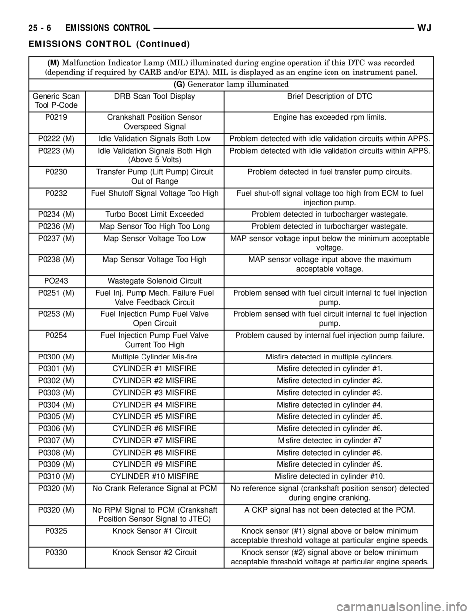
(M)Malfunction Indicator Lamp (MIL) illuminated during engine operation if this DTC was recorded
(depending if required by CARB and/or EPA). MIL is displayed as an engine icon on instrument panel.
(G)Generator lamp illuminated
Generic Scan
Tool P-CodeDRB Scan Tool Display Brief Description of DTC
P0219 Crankshaft Position Sensor
Overspeed SignalEngine has exceeded rpm limits.
P0222 (M) Idle Validation Signals Both Low Problem detected with idle validation circuits within APPS.
P0223 (M) Idle Validation Signals Both High
(Above 5 Volts)Problem detected with idle validation circuits within APPS.
P0230 Transfer Pump (Lift Pump) Circuit
Out of RangeProblem detected in fuel transfer pump circuits.
P0232 Fuel Shutoff Signal Voltage Too High Fuel shut-off signal voltage too high from ECM to fuel
injection pump.
P0234 (M) Turbo Boost Limit Exceeded Problem detected in turbocharger wastegate.
P0236 (M) Map Sensor Too High Too Long Problem detected in turbocharger wastegate.
P0237 (M) Map Sensor Voltage Too Low MAP sensor voltage input below the minimum acceptable
voltage.
P0238 (M) Map Sensor Voltage Too High MAP sensor voltage input above the maximum
acceptable voltage.
PO243 Wastegate Solenoid Circuit
P0251 (M) Fuel Inj. Pump Mech. Failure Fuel
Valve Feedback CircuitProblem sensed with fuel circuit internal to fuel injection
pump.
P0253 (M) Fuel Injection Pump Fuel Valve
Open CircuitProblem sensed with fuel circuit internal to fuel injection
pump.
P0254 Fuel Injection Pump Fuel Valve
Current Too HighProblem caused by internal fuel injection pump failure.
P0300 (M) Multiple Cylinder Mis-fire Misfire detected in multiple cylinders.
P0301 (M) CYLINDER #1 MISFIRE Misfire detected in cylinder #1.
P0302 (M) CYLINDER #2 MISFIRE Misfire detected in cylinder #2.
P0303 (M) CYLINDER #3 MISFIRE Misfire detected in cylinder #3.
P0304 (M) CYLINDER #4 MISFIRE Misfire detected in cylinder #4.
P0305 (M) CYLINDER #5 MISFIRE Misfire detected in cylinder #5.
P0306 (M) CYLINDER #6 MISFIRE Misfire detected in cylinder #6.
P0307 (M) CYLINDER #7 MISFIRE Misfire detected in cylinder #7
P0308 (M) CYLINDER #8 MISFIRE Misfire detected in cylinder #8.
P0309 (M) CYLINDER #9 MISFIRE Misfire detected in cylinder #9.
P0310 (M) CYLINDER #10 MISFIRE Misfire detected in cylinder #10.
P0320 (M) No Crank Referance Signal at PCM No reference signal (crankshaft position sensor) detected
during engine cranking.
P0320 (M) No RPM Signal to PCM (Crankshaft
Position Sensor Signal to JTEC)A CKP signal has not been detected at the PCM.
P0325 Knock Sensor #1 Circuit Knock sensor (#1) signal above or below minimum
acceptable threshold voltage at particular engine speeds.
P0330 Knock Sensor #2 Circuit Knock sensor (#2) signal above or below minimum
acceptable threshold voltage at particular engine speeds.
25 - 6 EMISSIONS CONTROLWJ
EMISSIONS CONTROL (Continued)
Page 2162 of 2199

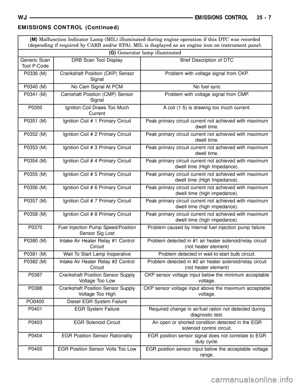
(M)Malfunction Indicator Lamp (MIL) illuminated during engine operation if this DTC was recorded
(depending if required by CARB and/or EPA). MIL is displayed as an engine icon on instrument panel.
(G)Generator lamp illuminated
Generic Scan
Tool P-CodeDRB Scan Tool Display Brief Description of DTC
P0336 (M) Crankshaft Position (CKP) Sensor
SignalProblem with voltage signal from CKP.
P0340 (M) No Cam Signal At PCM No fuel sync
P0341 (M) Camshaft Position (CMP) Sensor
SignalProblem with voltage signal from CMP.
P0350 Ignition Coil Draws Too Much
CurrentA coil (1-5) is drawing too much current.
P0351 (M) Ignition Coil # 1 Primary Circuit Peak primary circuit current not achieved with maximum
dwell time.
P0352 (M) Ignition Coil # 2 Primary Circuit Peak primary circuit current not achieved with maximum
dwell time.
P0353 (M) Ignition Coil # 3 Primary Circuit Peak primary circuit current not achieved with maximum
dwell time.
P0354 (M) Ignition Coil # 4 Primary Circuit Peak primary circuit current not achieved with maximum
dwell time (High Impedance).
P0355 (M) Ignition Coil # 5 Primary Circuit Peak primary circuit current not achieved with maximum
dwell time (High Impedance).
P0356 (M) Ignition Coil # 6 Primary Circuit Peak primary circuit current not achieved with maximum
dwell time (high impedance).
P0357 (M) Ignition Coil # 7 Primary Circuit Peak primary circuit current not achieved with maximum
dwell time (high impedance).
P0358 (M) Ignition Coil # 8 Primary Circuit Peak primary circuit current not achieved with maximum
dwell time (high impedance).
P0370 Fuel Injection Pump Speed/Position
Sensor Sig LostProblem caused by internal fuel injection pump failure.
P0380 (M) Intake Air Heater Relay #1 Control
CircuitProblem detected in #1 air heater solenoid/relay circuit
(not heater element)
P0381 (M) Wait To Start Lamp Inoperative Problem detected in wait-to-start bulb circuit.
P0382 (M) Intake Air Heater Relay #2 Control
CircuitProblem detected in #2 air heater solenoid/relay circuit
(not heater element)
P0387 Crankshaft Position Sensor Supply
Voltage Too LowCKP sensor voltage input below the minimum acceptable
voltage.
P0388 Crankshaft Position Sensor Supply
Voltage Too HighCKP sensor voltage input above the maximum acceptable
voltage.
PO0400 Diesel EGR System Failure
P0401 EGR System Failure Required change in air/fuel ration not detected during
diagnostic test.
P0403 EGR Solenoid Circuit An open or shorted condition detected in the EGR
solenoid control circuit.
P0404 EGR Position Sensor Rationality EGR position sensor signal does not correlate to EGR
duty cycle.
P0405 EGR Position Sensor Volts Too Low EGR position sensor input below the acceptable voltage
range.
WJEMISSIONS CONTROL 25 - 7
EMISSIONS CONTROL (Continued)
Page 2173 of 2199

tive system and seal the evaporative system so the
leak detection test can be run.
The primary components within the assembly are:
A three port solenoid that activates both of the func-
tions listed above; a pump which contains a switch,
two check valves and a spring/diaphragm, a canister
vent valve (CVV) seal which contains a spring loaded
vent seal valve.
Immediately after a cold start, between predeter-
mined temperature thresholds limits, the three port
solenoid is briefly energized. This initializes the
pump by drawing air into the pump cavity and also
closes the vent seal. During non test conditions the
vent seal is held open by the pump diaphragm
assembly which pushes it open at the full travel posi-
tion. The vent seal will remain closed while the
pump is cycling due to the reed switch triggering of
the three port solenoid that prevents the diaphragm
assembly from reaching full travel. After the brief
initialization period, the solenoid is de-energized
allowing atmospheric pressure to enter the pump
cavity, thus permitting the spring to drive the dia-
phragm which forces air out of the pump cavity and
into the vent system. When the solenoid is energized
and de energized, the cycle is repeated creating flow
in typical diaphragm pump fashion. The pump is con-
trolled in 2 modes:
Pump Mode:The pump is cycled at a fixed rate to
achieve a rapid pressure build in order to shorten the
overall test length.
Test Mode:The solenoid is energized with a fixed
duration pulse. Subsequent fixed pulses occur when
the diaphragm reaches the Switch closure point.
The spring in the pump is set so that the system
will achieve an equalized pressure of about 7.5º
water. The cycle rate of pump strokes is quite rapid
as the system begins to pump up to this pressure. As
the pressure increases, the cycle rate starts to drop
off. If there is no leak in the system, the pump would
eventually stop pumping at the equalized pressure. If
there is a leak, it will continue to pump at a rate rep-
resentative of the flow characteristic of the size of the
leak. From this information we can determine if the
leak is larger than the required detection limit (cur-
rently set at .040º orifice by CARB). If a leak is
revealed during the leak test portion of the test, the
test is terminated at the end of the test mode and no
further system checks will be performed.
After passing the leak detection phase of the test,
system pressure is maintained by turning on the
LDP's solenoid until the purge system is activated.
Purge activation in effect creates a leak. The cycle
rate is again interrogated and when it increases due
to the flow through the purge system, the leak check
portion of the diagnostic is complete.The canister vent valve will unseal the system
after completion of the test sequence as the pump
diaphragm assembly moves to the full travel position.
Evaporative system functionality will be verified by
using the stricter evap purge flow monitor. At an
appropriate warm idle the LDP will be energized to
seal the canister vent. The purge flow will be clocked
up from some small value in an attempt to see a
shift in the 02 control system. If fuel vapor, indicated
by a shift in the 02 control, is present the test is
passed. If not, it is assumed that the purge system is
not functioning in some respect. The LDP is again
turned off and the test is ended.
MISFIRE MONITOR
Excessive engine misfire results in increased cata-
lyst temperature and causes an increase in HC emis-
sions. Severe misfires could cause catalyst damage.
To prevent catalytic convertor damage, the PCM
monitors engine misfire.
The Powertrain Control Module (PCM) monitors
for misfire during most engine operating conditions
(positive torque) by looking at changes in the crank-
shaft speed. If a misfire occurs the speed of the
crankshaft will vary more than normal.
FUEL SYSTEM MONITOR
To comply with clean air regulations, vehicles are
equipped with catalytic converters. These converters
reduce the emission of hydrocarbons, oxides of nitro-
gen and carbon monoxide. The catalyst works best
when the Air Fuel (A/F) ratio is at or near the opti-
mum of 14.7 to 1.
The PCM is programmed to maintain the optimum
air/fuel ratio of 14.7 to 1. This is done by making
short term corrections in the fuel injector pulse width
based on the O2S sensor output. The programmed
memory acts as a self calibration tool that the engine
controller uses to compensate for variations in engine
specifications, sensor tolerances and engine fatigue
over the life span of the engine. By monitoring the
actual fuel-air ratio with the O2S sensor (short term)
and multiplying that with the program long-term
(adaptive) memory and comparing that to the limit,
it can be determined whether it will pass an emis-
sions test. If a malfunction occurs such that the PCM
cannot maintain the optimum A/F ratio, then the
MIL will be illuminated.
CATALYST MONITOR
To comply with clean air regulations, vehicles are
equipped with catalytic converters. These converters
reduce the emission of hydrocarbons, oxides of nitro-
gen and carbon monoxide.
Normal vehicle miles or engine misfire can cause a
catalyst to decay. This can increase vehicle emissions
25 - 18 EMISSIONS CONTROLWJ
EMISSIONS CONTROL (Continued)