2003 JEEP GRAND CHEROKEE stall
[x] Cancel search: stallPage 173 of 2199

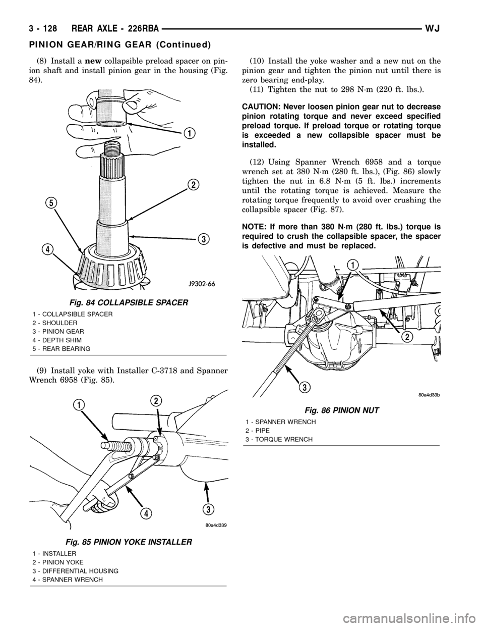
(8) Install anewcollapsible preload spacer on pin-
ion shaft and install pinion gear in the housing (Fig.
84).
(9) Install yoke with Installer C-3718 and Spanner
Wrench 6958 (Fig. 85).(10) Install the yoke washer and a new nut on the
pinion gear and tighten the pinion nut until there is
zero bearing end-play.
(11) Tighten the nut to 298 N´m (220 ft. lbs.).
CAUTION: Never loosen pinion gear nut to decrease
pinion rotating torque and never exceed specified
preload torque. If preload torque or rotating torque
is exceeded a new collapsible spacer must be
installed.
(12) Using Spanner Wrench 6958 and a torque
wrench set at 380 N´m (280 ft. lbs.), (Fig. 86) slowly
tighten the nut in 6.8 N´m (5 ft. lbs.) increments
until the rotating torque is achieved. Measure the
rotating torque frequently to avoid over crushing the
collapsible spacer (Fig. 87).
NOTE: If more than 380 N´m (280 ft. lbs.) torque is
required to crush the collapsible spacer, the spacer
is defective and must be replaced.
Fig. 84 COLLAPSIBLE SPACER
1 - COLLAPSIBLE SPACER
2 - SHOULDER
3 - PINION GEAR
4 - DEPTH SHIM
5 - REAR BEARING
Fig. 85 PINION YOKE INSTALLER
1 - INSTALLER
2 - PINION YOKE
3 - DIFFERENTIAL HOUSING
4 - SPANNER WRENCH
Fig. 86 PINION NUT
1 - SPANNER WRENCH
2 - PIPE
3 - TORQUE WRENCH
3 - 128 REAR AXLE - 226RBAWJ
PINION GEAR/RING GEAR (Continued)
Page 174 of 2199

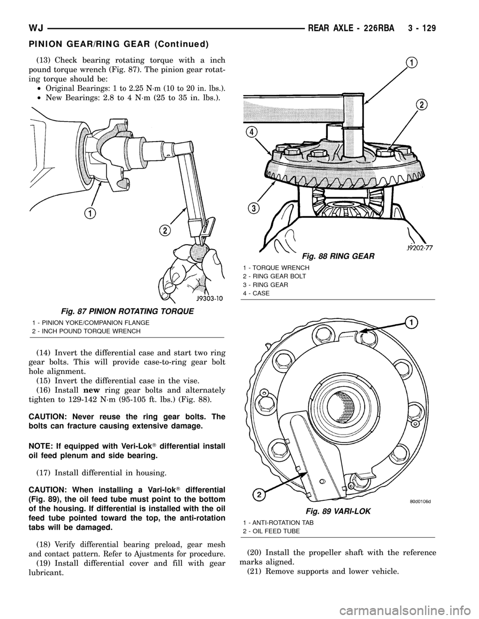
(13) Check bearing rotating torque with a inch
pound torque wrench (Fig. 87). The pinion gear rotat-
ing torque should be:
²
Original Bearings: 1 to 2.25 N´m (10 to 20 in. lbs.).
²New Bearings: 2.8 to 4 N´m (25 to 35 in. lbs.).
(14) Invert the differential case and start two ring
gear bolts. This will provide case-to-ring gear bolt
hole alignment.
(15) Invert the differential case in the vise.
(16) Installnewring gear bolts and alternately
tighten to 129-142 N´m (95-105 ft. lbs.) (Fig. 88).
CAUTION: Never reuse the ring gear bolts. The
bolts can fracture causing extensive damage.
NOTE: If equipped with Veri-LokTdifferential install
oil feed plenum and side bearing.
(17) Install differential in housing.
CAUTION: When installing a Vari-lokTdifferential
(Fig. 89), the oil feed tube must point to the bottom
of the housing. If differential is installed with the oil
feed tube pointed toward the top, the anti-rotation
tabs will be damaged.
(18)
Verify differential bearing preload, gear mesh
and contact pattern. Refer to Ajustments for procedure.
(19) Install differential cover and fill with gear
lubricant.(20) Install the propeller shaft with the reference
marks aligned.
(21) Remove supports and lower vehicle.
Fig. 87 PINION ROTATING TORQUE
1 - PINION YOKE/COMPANION FLANGE
2 - INCH POUND TORQUE WRENCH
Fig. 88 RING GEAR
1 - TORQUE WRENCH
2 - RING GEAR BOLT
3 - RING GEAR
4 - CASE
Fig. 89 VARI-LOK
1 - ANTI-ROTATION TAB
2 - OIL FEED TUBE
WJREAR AXLE - 226RBA 3 - 129
PINION GEAR/RING GEAR (Continued)
Page 176 of 2199

BRAKES
TABLE OF CONTENTS
page page
BRAKES - BASE........................... 1BRAKES - ABS........................... 41
BRAKES - BASE
TABLE OF CONTENTS
page page
BRAKES - BASE
DESCRIPTION..........................2
DIAGNOSIS AND TESTING - BASE BRAKE
SYSTEM.............................2
STANDARD PROCEDURE
STANDARD PROCEDURE - MANUAL
BLEEDING............................5
STANDARD PROCEDURE - PRESSURE
BLEEDING............................5
SPECIFICATIONS
BRAKE COMPONENTS..................6
TORQUE CHART......................6
SPECIAL TOOLS
BASE BRAKES........................7
BRAKE FLUID LEVEL SWITCH
REMOVAL.............................7
INSTALLATION..........................7
RED BRAKE WARN INDICATOR SWITCH
DESCRIPTION..........................7
OPERATION............................7
DIAGNOSIS AND TESTING - RED BRAKE
WARNING LAMP.......................7
ADJUSTABLE PEDAL SWITCH
REMOVAL.............................8
INSTALLATION..........................8
BRAKE LINES
DESCRIPTION..........................8
DIAGNOSIS AND TESTING - BRAKE HOSES
AND LINES...........................8
STANDARD PROCEDURE
STANDARD PROCEDURE - DOUBLE
INVERTED FLARING....................9
STANDARD PROCEDURE - ISO FLARING . . . 9
BRAKE PADS / SHOES
DESCRIPTION
DESCRIPTION - FRONT DISC BRAKE
SHOES.............................10DESCRIPTION - REAR DISC BRAKE SHOES . 10
OPERATION
OPERATION - FRONT DISC BRAKE SHOES . 10
OPERATION - REAR DISC BRAKE SHOES . . 10
REMOVAL
REMOVAL- FRONT DISC BRAKE SHOES . . . 11
REMOVAL - REAR DISC BRAKE SHOES....12
INSTALLATION
INSTALLATION - FRONT DISC BRAKE
SHOES.............................13
INSTALLATION - REAR DISC BRAKE
SHOES.............................14
DISC BRAKE CALIPERS
REMOVAL
REMOVAL - FRONT DISC BRAKE CALIPER . 14
REMOVAL - REAR DISC BRAKE CALIPER . . 15
DISASSEMBLY
DISASSEMBLY - FRONT DISC BRAKE
CALIPER............................17
DISASSEMBLY - REAR DISC BRAKE
CALIPER............................18
CLEANING - DISC BRAKE CALIPER.........19
INSPECTION - DISC BRAKE CALIPER.......19
ASSEMBLY
ASSEMBLY - FRONT DISC BRAKE CALIPER . 20
ASSEMBLY - REAR DISC BRAKE CALIPER . 21
INSTALLATION
INSTALLATION - FRONT DISC BRAKE
CALIPER............................22
INSTALLATION - REAR DISC BRAKE
CALIPER............................22
FLUID
DIAGNOSIS AND TESTING - BRAKE FLUID
CONTAMINATION.....................22
SPECIFICATIONS
BRAKE FLUID........................23
FLUID RESERVOIR
REMOVAL.............................23
WJBRAKES 5 - 1
Page 177 of 2199

INSTALLATION.........................23
MASTER CYLINDER
DESCRIPTION.........................23
OPERATION...........................24
DIAGNOSIS AND TESTING - MASTER
CYLINDER/POWER BOOSTER...........24
STANDARD PROCEDURE - MASTER
CYLINDER BLEEDING PROCEDURE......25
REMOVAL.............................25
INSTALLATION.........................25
PEDAL
DESCRIPTION
DESCRIPTION - STANDARD PEDAL.......25
DESCRIPTION - ADJUSTABLE PEDALS....25
OPERATION...........................26
REMOVAL
REMOVAL - NON-ADJUSTABLE PEDAL....26
REMOVAL - ADJUSTABLE PEDALS........27
INSTALLATION
INSTALLATION - NON-ADJUSTABLE PEDAL . 28
INSTALLATION - ADJUSTABLE PEDALS....28
PEDAL MOTOR
REMOVAL.............................28
INSTALLATION.........................28
POWER BRAKE BOOSTER
DESCRIPTION.........................29
OPERATION...........................29
REMOVAL.............................31
INSTALLATION.........................31
ROTORS
DIAGNOSIS AND TESTING
DIAGNOSIS AND TESTING - FRONT DISC
BRAKE ROTOR.......................31DIAGNOSIS AND TESTING - REAR DISC
BRAKE ROTOR.......................32
STANDARD PROCEDURE - DISC ROTOR
MACHINING..........................33
REMOVAL
REMOVAL - FRONT DISC BRAKE ROTOR . . 33
REMOVAL - REAR DISC BRAKE ROTOR . . . 33
INSTALLATION
INSTALLATION - FRONT DISC BRAKE
ROTOR .............................34
INSTALLATION - REAR DISC BRAKE
ROTOR .............................34
PARKING BRAKE
OPERATION...........................34
DIAGNOSIS AND TESTING - PARKING BRAKE . 34
CABLES
REMOVAL
REMOVAL - FRONT PARKING BRAKE
CABLE..............................35
REMOVAL - REAR PARKING BRAKE
CABLES............................36
INSTALLATION
INSTALLATION - FRONT PARKING BRAKE
CABLE..............................37
INSTALLATION - REAR PARKING BRAKE
CABLES............................37
LEVER
REMOVAL.............................38
INSTALLATION.........................39
SHOES
REMOVAL.............................39
INSTALLATION.........................39
ADJUSTMENTS - PARKING BRAKE SHOE....40
BRAKES - BASE
DESCRIPTION
Dual piston disc brake calipers are used on the
front. Single piston disc brake calipers are used on
the rear. Ventilated disc brake rotors are used on the
front and solid rotors are used on the rear.
Power brake assist is supplied by a vacuum oper-
ated, dual diaphragm power brake booster. The mas-
ter cylinder used for all applications has an
aluminum body and nylon reservoir with single filler
cap. A fluid level indicator is mounted to the side of
the reservoir.
The braking force of the rear wheels is controlled
by electronic brake distribution (EBD). The EBD
functions like a rear proportioning valve. The EBD
system uses the ABS system to control the slip of the
rear wheels in partial braking range. The braking
force of the rear wheels is controlled electronically by
using the inlet and outlet valves located in the HCU.
Factory installed brake linings on all models con-
sists of organic base material combined with metallic
particles.
DIAGNOSIS AND TESTING - BASE BRAKE
SYSTEM
Base brake components consist of the brake shoes,
calipers, rear park brake drums/rotors, front brake
rotors, brake lines, master cylinder, booster, HCU
and parking brake shoes.
Brake diagnosis involves determining if the prob-
lem is related to a mechanical, hydraulic, electrical
or vacuum operated component.
The first diagnosis step is the preliminary check.
PRELIMINARY BRAKE CHECK
(1) Check condition of tires and wheels. Damaged
wheels and worn, damaged, or underinflated tires
can cause pull, shudder, vibration, and a condition
similar to grab.
5 - 2 BRAKES - BASEWJ
Page 182 of 2199

SPECIAL TOOLS
BASE BRAKESBRAKE FLUID LEVEL SWITCH
REMOVAL
(1) Remove the wire connector from the fluid level
sensor.
(2) From the same side of the master cylinder res-
ervoir release the sensor locking taps with a small
screw driver.
(3) Pull the sensor out of the reservoir from the
connector side of the sensor.
INSTALLATION
(1) Install the sensor with a new o-ring into the
reservoir until the locking tabs are engaged.
(2) Install the wire connector to the fluid level sen-
sor.
RED BRAKE WARN INDICATOR
SWITCH
DESCRIPTION
A red warning lamp is used for the service brake
portion of the hydraulic system. The lamp is located
in the instrument cluster.
OPERATION
The lamp is turned on momentarily when the igni-
tion switch is turn to the on position. This is a self
test to verify the lamp is operational.
The red warning light alerts the driver if the fluid
level is low or the parking brakes are applied. A red
warning lamp with an amber warning lamp may
indicate a electronic brake distribution fault.
DIAGNOSIS AND TESTING - RED BRAKE
WARNING LAMP
The red warning lamp illuminates when the park-
ing brake is applied or when the fluid level in the
master cylinder is low. It will also illuminate at start
up as part of a bulb check.
If the light comes on, first verify that the parking
brakes are fully released. Then check pedal action
and fluid level. If a problem is confirmed, inspect the
brake hydraulic system for leaks.
A red warning lamp with a amber warning lamp
may indicate a electronic brake distribution fault.
Installer Caliper Dust Boot 8280
Handle C-4171
Adapter Pressure Bleeder 6921
WJBRAKES - BASE 5 - 7
BRAKES - BASE (Continued)
Page 183 of 2199

ADJUSTABLE PEDAL SWITCH
REMOVAL
(1) Remove the steering column opening cover
(Fig. 2)(Refer to 23 - BODY/INSTRUMENT PANEL/
STEERING COLUMN OPENING COVER - REMOV-
AL).
(2) Disconnect the electrical connector from the
adjustable pedal switch.
(3) Remove the switch from the steering column
opening cover by squeezing the retaining clips
together and pushing the switch outwards (Fig. 3).
INSTALLATION
(1) Install the switch to the steering column open-
ing cover by pushing the switch inwards seating the
retaining clips to the steering column opening cover
(Fig. 3).
(2) Reconnect the electrical connector to the
adjustable pedal switch.
(3) Install the steering column opening cover (Fig.
2)(Refer to 23 - BODY/INSTRUMENT PANEL/
STEERING COLUMN OPENING COVER - INSTAL-
LATION).
BRAKE LINES
DESCRIPTION
Flexible rubber hose is used at both front brakes,
rear brakes and at the rear axle junction block. Dou-
ble walled steel tubing is used. Double inverted style
and ISO style flares are used on the brake lines.
DIAGNOSIS AND TESTING - BRAKE HOSES
AND LINES
Flexible rubber hose is used at both front and rear
brakes and at the rear axle junction block. Inspect
the hoses whenever the brake system is serviced, at
every engine oil change, or whenever the vehicle is in
for service.
Inspect the hoses for surface cracking, scuffing, or
worn spots. Replace any brake hose immediately if
the fabric casing of the hose is exposed due to cracks
or abrasions.
Also check brake hose installation. Faulty installa-
tion can result in kinked, twisted hoses, or contact
with the wheels and tires or other chassis compo-
nents. All of these conditions can lead to scuffing,
cracking and eventual failure.
The steel brake lines should be inspected periodi-
cally for evidence of corrosion, twists, kinks, leaks, or
other damage. Heavily corroded lines will eventually
rust through causing leaks. In any case, corroded or
damaged brake lines should be replaced.
Factory replacement brake lines and hoses are rec-
ommended to ensure quality, correct length and supe-
rior fatigue life. Care should be taken to make sure
that brake line and hose mating surfaces are clean
and free from nicks and burrs. Also remember that
right and left brake hoses are not interchangeable.
Use new copper gaskets at all caliper connections.
Be sure brake line connections are properly made
(not cross threaded) and tightened to recommended
torque.
Fig. 2 STEERING COLUMN OPENING COVER
REMOVAL/INSTALL
1 - INSTRUMENT PANEL TOP PAD
2 - STEERING COLUMN OPENING COVER
3 - SCREW (3)
Fig. 3 ADJUSTABLE PEDAL SWITCH
1 - RETAINING CLIPS
2 - ELECTRICAL CONNECTION
5 - 8 BRAKES - BASEWJ
Page 184 of 2199

STANDARD PROCEDURE
STANDARD PROCEDURE - DOUBLE INVERTED
FLARING
A preformed metal brake tube is recommended and
preferred for all repairs. However, double-wall steel
tube can be used for emergency repair when factory
replacement parts are not readily available.
Special bending tools are needed to avoid kinking
or twisting of metal brake tubes. Special flaring tools
are needed to make a double inverted flare or ISO
flare.
(1) Cut off damaged tube with Tubing Cutter.
(2) Ream cut edges of tubing to ensure proper
flare.
(3) Install replacement tube nut on the tube.
(4) Insert tube in flaring tool.
(5) Place gauge form over the end of the tube.
(6) Push tubing through flaring tool jaws until
tube contacts recessed notch in gauge that matches
tube diameter.
(7) Tighten the tool bar on the tube
(8) Insert plug on gauge in the tube. Then swing
compression disc over gauge and center tapered flar-
ing screw in recess of compression disc (Fig. 4).
(9) Tighten tool handle until plug gauge is
squarely seated on jaws of flaring tool. This will start
the inverted flare.
(10) Remove the plug gauge and complete the
inverted flare.
STANDARD PROCEDURE - ISO FLARING
A preformed metal brake tube is recommended and
preferred for all repairs. However, double-wall steel
tube can be used for emergency repair when factory
replacement parts are not readily available.
Special bending tools are needed to avoid kinking
or twisting of metal brake tubes. Special flaring tools
are needed to make a double inverted flare or ISO
flare.
To make a ISO flare use Snap-OntFlaring Tool
TFM-428 or equivalent.
(1) Cut off damaged tube with Tubing Cutter.
(2) Remove any burrs from the inside of the tube.
(3) Install tube nut on the tube.
(4) Position the tube in the flaring tool flush with
the top of the tool bar (Fig. 5). Then tighten the tool
bar on the tube.
(5) Install the correct size adaptor on the flaring
tool yoke screw.
(6) Lubricate the adaptor.
(7) Align the adaptor and yoke screw over the tube
(Fig. 5).
(8) Turn the yoke screw in until the adaptor is
squarely seated on the tool bar.
Fig. 4 Inverted
Fig. 5 ISO Flaring
1 - ADAPTER
2 - LUBRICATE HERE
3 - PILOT
4 - FLUSH WITH BAR
5 - TUBING
6 - BAR ASSEMBLY
WJBRAKES - BASE 5 - 9
BRAKE LINES (Continued)
Page 188 of 2199

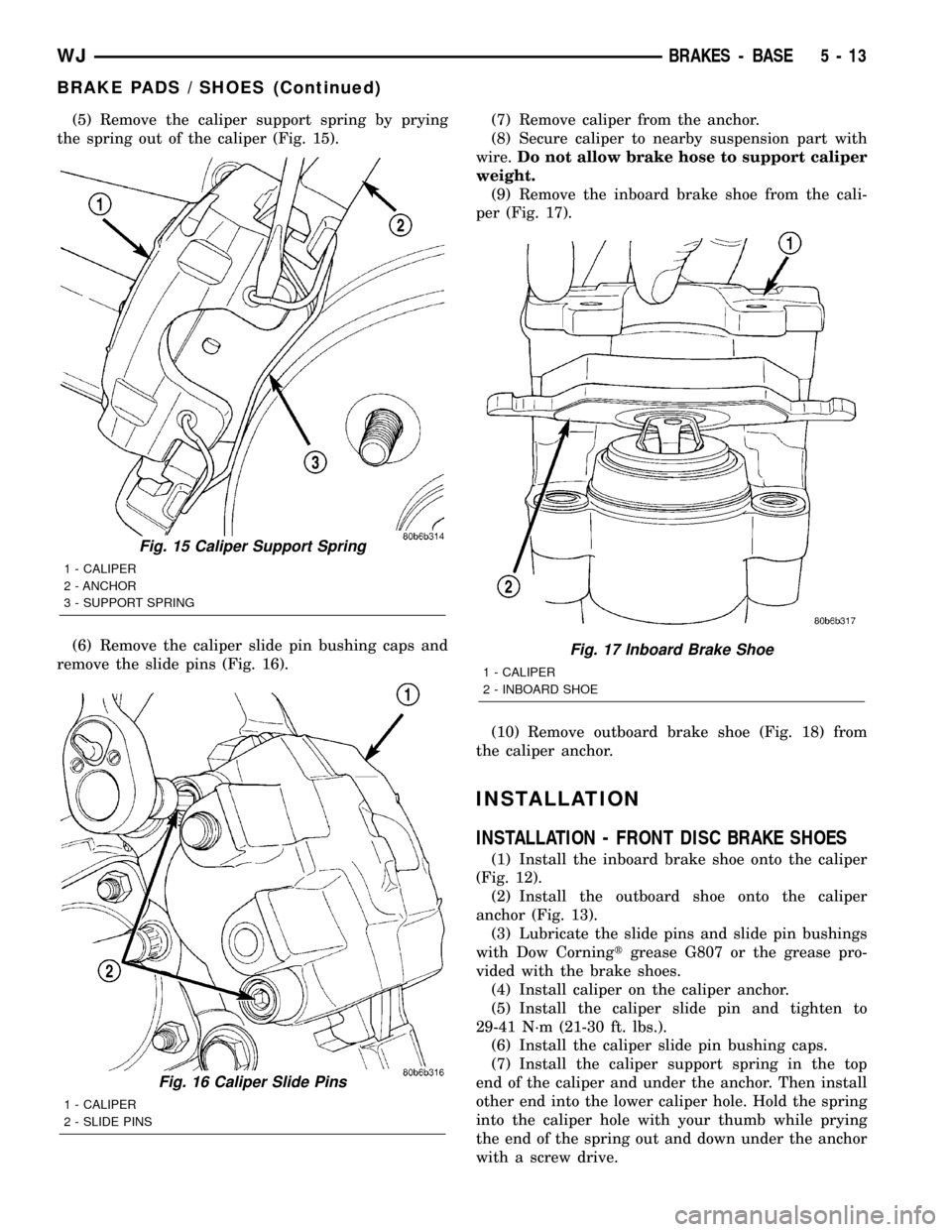
(5) Remove the caliper support spring by prying
the spring out of the caliper (Fig. 15).
(6) Remove the caliper slide pin bushing caps and
remove the slide pins (Fig. 16).(7) Remove caliper from the anchor.
(8) Secure caliper to nearby suspension part with
wire.Do not allow brake hose to support caliper
weight.
(9) Remove the inboard brake shoe from the cali-
per (Fig. 17).
(10) Remove outboard brake shoe (Fig. 18) from
the caliper anchor.
INSTALLATION
INSTALLATION - FRONT DISC BRAKE SHOES
(1) Install the inboard brake shoe onto the caliper
(Fig. 12).
(2) Install the outboard shoe onto the caliper
anchor (Fig. 13).
(3) Lubricate the slide pins and slide pin bushings
with Dow Corningtgrease G807 or the grease pro-
vided with the brake shoes.
(4) Install caliper on the caliper anchor.
(5) Install the caliper slide pin and tighten to
29-41 N´m (21-30 ft. lbs.).
(6) Install the caliper slide pin bushing caps.
(7) Install the caliper support spring in the top
end of the caliper and under the anchor. Then install
other end into the lower caliper hole. Hold the spring
into the caliper hole with your thumb while prying
the end of the spring out and down under the anchor
with a screw drive.
Fig. 15 Caliper Support Spring
1 - CALIPER
2 - ANCHOR
3 - SUPPORT SPRING
Fig. 16 Caliper Slide Pins
1 - CALIPER
2 - SLIDE PINS
Fig. 17 Inboard Brake Shoe
1 - CALIPER
2 - INBOARD SHOE
WJBRAKES - BASE 5 - 13
BRAKE PADS / SHOES (Continued)