2003 JEEP GRAND CHEROKEE Charge
[x] Cancel search: ChargePage 1255 of 2199

(7) Remove the fan assembly from the water pump
(Refer to 7 - COOLING/ENGINE/RADIATOR FAN -
REMOVAL).
(8) Remove the fan shroud.
(9) Disconnect the transmission fluid cooler lines
(automatic transmission).
(10) Discharge the A/C system (Refer to 24 -
HEATING & AIR CONDITIONING/PLUMBING -
STANDARD PROCEDURE).
(11) Remove the service valves and cap the com-
pressor ports.
(12) Remove the radiator or radiator/condenser (if
equipped with A/C).
(13) Disconnect the heater hoses at the engine
thermostat housing and water pump.
(14) Disconnect the accelerator cable, transmission
line pressure cable and speed control cable (if
equipped) from the throttle body.
(15) Remove cables from the bracket and secure
out of the way.
(16) Disconnect the body ground at the engine.
(17) Disconnect the following connectors and
secure their harness out of the way.
²Power steering pressure switch
²Coolant temperature sensor
²Six (6) fuel injector connectors
²Intake air temperature sensor
²Throttle position sensor
²Map sensor
²Crankshaft position sensor
²Oxygen sensor
²Camshaft position sensor
²Generator connector and B+ terminal wire
(18) Disconnect the coil rail electrical connections
and the oil pressure switch connector.
(19) Perform the fuel pressure release procedure
(Refer to 14 - FUEL SYSTEM/FUEL DELIVERY -
STANDARD PROCEDURE).
(20) Disconnect the fuel supply line at the injector
rail (Refer to 14 - FUEL SYSTEM/FUEL DELIVERY/
QUICK CONNECT FITTING - STANDARD PROCE-
DURE).
(21) Remove the fuel line bracket from the intake
manifold.
(22) Remove the air cleaner assembly (Fig. 5).
(23) Disconnect the hoses from the fittings at the
steering gear.
(24) Drain the pump reservoir.
(25) Cap the fittings on the hoses and steering
gear to prevent foreign objects from entering the sys-
tem.
(26) Raise and support the vehicle.
(27) Disconnect the wires from the engine starter
motor solenoid.(28) Remove the engine starter motor (Refer to 8 -
ELECTRICAL/STARTING/STARTER MOTOR -
REMOVAL).
(29) Disconnect the oxygen sensor from the
exhaust pipe.
(30) Disconnect the exhaust pipe from the mani-
fold.
(31) Remove the exhaust pipe support.
(32) Remove the bending brace (Refer to 9 -
ENGINE/ENGINE BLOCK/STRUCT SUPPORT -
REMOVAL).
(33) Remove the engine flywheel/converter housing
access cover.
(34) Mark the converter and drive plate location.
(35) Remove the converter-to-drive plate bolts.
(36) Remove the upper engine flywheel/converter
housing bolts and loosen the bottom bolts.
(37) Remove the engine mount cushion-to-engine
compartment bracket bolts.
(38) Lower the vehicle.
(39) Attach a lifting device to the engine.
(40) Raise the engine off the front supports.
(41) Place a support or floor jack under the con-
verter (or engine flywheel) housing.
(42) Remove the remaining converter (or engine
flywheel) housing bolts.
(43) Lift the engine out of the engine compart-
ment.
Fig. 5 Air Cleaner Assembly
1 - POWER STEERING PUMP
2 - AIR CLEANER ASSEMBLY
9 - 12 ENGINE - 4.0LWJ
ENGINE - 4.0L (Continued)
Page 1256 of 2199

INSTALLATION
CAUTION: When installing the engine into a vehicle
equipped with an automatic transmission, be care-
ful not to damage the trigger wheel on the engine
flywheel.
(1) Attach a lifting device to the engine and lower
the engine into the engine compartment. For easier
installation, it may be necessary to remove the
engine mount bracket as an aid in alignment of the
engine to the transmission.
(2) Align the transmission torque converter hous-
ing with the engine.
(3) Loosely install the converter housing lower
bolts and install the next higher bolt and nut on each
side.
(4) Tighten all 4 bolts finger tight.
(5) Install the engine mount brackets (if removed).
(6) Lower the engine and engine mount brackets
onto the engine compartment cushions. Install the
bolts and finger tighten the nuts.
(7) Remove the engine lifting device.
(8) Raise and support the vehicle.
(9) Install the remaining engine flywheel/converter
housing bolts. Tighten all bolts to 38 N´m (28 ft. lbs.)
torque.
(10) Install the converter-to-drive plate bolts.
(11) Ensure the installation reference marks are
aligned.
(12) Install the engine flywheel/converter housing
access cover.
(13) Install the exhaust pipe support and tighten
the screw.
(14) Install the engine bending brace (Refer to 9 -
ENGINE/ENGINE BLOCK/STRUCT SUPPORT -
INSTALLATION).
(15) Tighten the engine mount-to-bracket bolts.
(16) Connect the vehicle speed sensor wire connec-
tions and tighten the screws.
(17) Connect the exhaust pipe to the manifold.
(18) Install the engine starter motor (Refer to 8 -
ELECTRICAL/STARTING/STARTER MOTOR -
INSTALLATION).
(19) Connect the wires to the engine starter motor
solenoid.
(20) Lower the vehicle.
(21) Connect all the vacuum hoses and wire con-
nectors identified during engine removal.
(22) Remove protective caps from the power steer-
ing hoses.
(23) Connect the hoses to the fittings at the steer-
ing gear. Tighten the nut to 52 N´m (38 ft. lbs.)
torque.
(24) Fill the pump reservoir with fluid.(25) Inspect the fuel supply line o-ring(s) and
replace if necessary. Connect fuel supply line to injec-
tior rail and verify connection by pulling outward on
the line.
(26) Install the fuel line bracket to the intake
manifold.
(27) Connect the coil rail electrical connectors and
oil pressure switch connector.
(28) Connect the following electrical connectors:
²Power steering pressure switch
²Coolant temperature sensor
²Six (6) fuel injector connectors
²Intake air temperature sensor
²Throttle position sensor
²Map sensor
²Crankshaft position sensor
²Oxygen sensor
²Camshaft position sensor
²Generator connector and B+ terminal wire
(29) Connect all previously removed vacuum hoses.
(30) Connect the body ground strap.
(31) Install the throttle, transmission line pres-
sure, and speed control cables to their mounting
bracket and connect them to the throttle body.
(32) Connect the heater hoses at the engine ther-
mostat housing and water pump.
(33) Install the fan assembly (Refer to 7 - COOL-
ING/ENGINE/RADIATOR FAN - INSTALLATION).
(34) Place the fan shroud in position over the fan.
(35) Install the radiator (Refer to 7 - COOLING/
ENGINE/RADIATOR - INSTALLATION).
(36) Connect the service valves to the A/C com-
pressor ports, if equipped with A/C.
(37) Charge the air conditioner system (Refer to 24
- HEATING & AIR CONDITIONING/PLUMBING -
STANDARD PROCEDURE).
(38) Connect the radiator hoses and automatic
transmission fluid cooler pipes, if equipped.
(39) Install the fan shroud to the radiator or radi-
ator/condenser (if equipped with A/C).
(40) Install upper radiator support.
(41) Connect the upper radiator hose and tighten
the clamp.
(42) Connect the lower radiator hose and tighten
the clamp.
(43) Fill crankcase with engine oil. (Refer to
LUBRICATION & MAINTENANCE/FLUID CAPACI-
TIES - SPECIFICATIONS) for correct capacities.
(44) Fill the cooling system with reusable coolant
or new coolant (Refer to 7 - COOLING - STANDARD
PROCEDURE).
(45) Align the hood to the scribe marks. Install the
hood.
(46) Install the air cleaner assembly.
(47) Install the battery and connect the battery
cable.
WJENGINE - 4.0L 9 - 13
ENGINE - 4.0L (Continued)
Page 1265 of 2199
(12) Install the push rods, rocker arms, pivots and
bridges in the order they were removed (Refer to 9 -
ENGINE/CYLINDER HEAD/ROCKER ARM /
ADJUSTER ASSY - INSTALLATION).
(13) Install the engine cylinder head cover (Refer
to 9 - ENGINE/CYLINDER HEAD/CYLINDER
HEAD COVER(S) - INSTALLATION).
(14) Attach the air conditioner compressor mount-
ing bracket to the engine cylinder head and block.
Tighten the bolts to 40 N´m (30 ft. lbs.) torque.
(15) Attach the air conditioning compressor to the
bracket. Tighten the bolts to 27 N´m (20 ft. lbs.)
torque.
CAUTION: The serpentine drive belt must be routed
correctly. Incorrect routing can cause the water
pump to turn in the opposite direction causing the
engine to overheat.
(16) Install the serpentine drive belt. (Refer to 7 -
COOLING/ACCESSORY DRIVE/DRIVE BELTS -
INSTALLATION).
(17) Install the air cleaner and ducting.
(18) Connect the hoses to the engine thermostat
housing and fill the cooling system to the specified
level (Refer to 7 - COOLING - STANDARD PROCE-
DURE).
(19) The automatic transmission throttle linkage
and cable must be adjusted after completing the
engine cylinder head installation (Refer to 21 -
TRANSMISSION/TRANSAXLE/AUTOMATIC - AW4/
THROTTLE VALVE CABLE - ADJUSTMENTS).
(20) Install the temperature sending unit and con-
nect the wire connector.
(21) If equipped with air conditioning, install A/C
compressor (Refer to 24 - HEATING & AIR CONDI-
TIONING/PLUMBING/A/C COMPRESSOR -
INSTALLATION) and charge A/C system (Refer to 24
- HEATING & AIR CONDITIONING/PLUMBING -
STANDARD PROCEDURE).
(22) Connect negative cable to battery.
WARNING: USE EXTREME CAUTION WHEN THE
ENGINE IS OPERATING. DO NOT STAND IN DIRECT
LINE WITH THE FAN. DO NOT PUT HANDS NEAR
THE PULLEYS, BELTS OR FAN. DO NOT WEAR
LOOSE CLOTHING.
(23) Operate the engine with the radiator cap off.
Inspect for leaks and continue operating the engine
until the engine thermostat opens. Add coolant, if
required.CYLINDER HEAD COVER(S)
DESCRIPTION
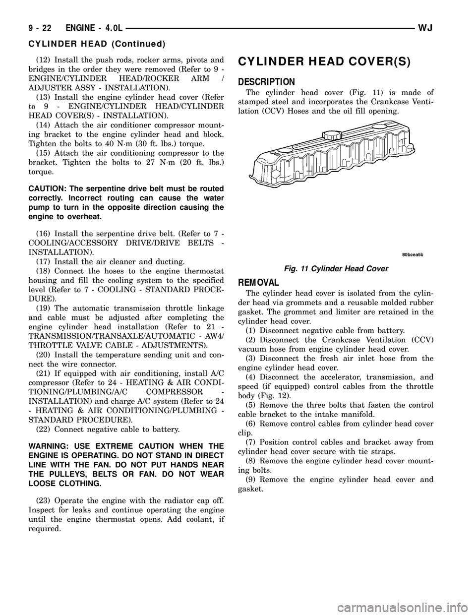
The cylinder head cover (Fig. 11) is made of
stamped steel and incorporates the Crankcase Venti-
lation (CCV) Hoses and the oil fill opening.
REMOVAL
The cylinder head cover is isolated from the cylin-
der head via grommets and a reusable molded rubber
gasket. The grommet and limiter are retained in the
cylinder head cover.
(1) Disconnect negative cable from battery.
(2) Disconnect the Crankcase Ventilation (CCV)
vacuum hose from engine cylinder head cover.
(3) Disconnect the fresh air inlet hose from the
engine cylinder head cover.
(4) Disconnect the accelerator, transmission, and
speed (if equipped) control cables from the throttle
body (Fig. 12).
(5) Remove the three bolts that fasten the control
cable bracket to the intake manifold.
(6) Remove control cables from cylinder head cover
clip.
(7) Position control cables and bracket away from
cylinder head cover secure with tie straps.
(8) Remove the engine cylinder head cover mount-
ing bolts.
(9) Remove the engine cylinder head cover and
gasket.
Fig. 11 Cylinder Head Cover
9 - 22 ENGINE - 4.0LWJ
CYLINDER HEAD (Continued)
Page 1287 of 2199
It is not necessary to charge the tappets with
engine oil. They will charge themselves within a very
short period of engine operation.
(1) Dip each tappet in MopartEngine Oil Supple-
ment, or equivalent.
(2) Use Hydraulic Valve Tappet Removal/Installa-
tion Tool to install each tappet in the same bore from
where it was originally removed.
(3) Install the cylinder head (Refer to 9 - ENGINE/
CYLINDER HEAD - INSTALLATION).
(4) Install the push rods in their original locations.
(5) Install the rocker arms and bridge and pivot
assemblies at their original locations. Loosely install
the capscrews at each bridge.
(6) Tighten the capscrews alternately, one turn at
a time, to avoid damaging the bridges. Tighten the
capscrews to 28 N´m (21 ft. lbs.) torque.
(7)
Pour the remaining MopartEngine Oil Supple-
ment, or equivalent over the entire valve actuating
assembly. The MopartEngine Oil Supplement, or equiv-
alent must remain with the engine oil for at least 1 609
km (1,000 miles). The oil supplement need not be
drained until the next scheduled oil change.
(8) Install the cylinder head cover (Refer to 9 -
ENGINE/CYLINDER HEAD/CYLINDER HEAD
COVER(S) - INSTALLATION).
PISTON & CONNECTING ROD
DESCRIPTION
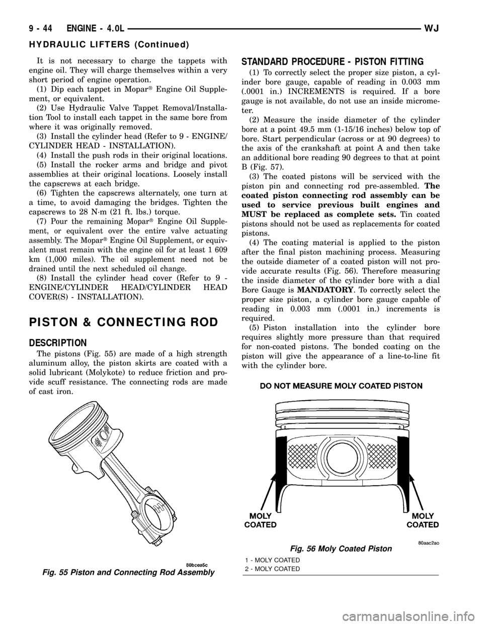
The pistons (Fig. 55) are made of a high strength
aluminum alloy, the piston skirts are coated with a
solid lubricant (Molykote) to reduce friction and pro-
vide scuff resistance. The connecting rods are made
of cast iron.
STANDARD PROCEDURE - PISTON FITTING
(1) To correctly select the proper size piston, a cyl-
inder bore gauge, capable of reading in 0.003 mm
(.0001 in.) INCREMENTS is required. If a bore
gauge is not available, do not use an inside microme-
ter.
(2) Measure the inside diameter of the cylinder
bore at a point 49.5 mm (1-15/16 inches) below top of
bore. Start perpendicular (across or at 90 degrees) to
the axis of the crankshaft at point A and then take
an additional bore reading 90 degrees to that at point
B (Fig. 57).
(3) The coated pistons will be serviced with the
piston pin and connecting rod pre-assembled.The
coated piston connecting rod assembly can be
used to service previous built engines and
MUST be replaced as complete sets.Tin coated
pistons should not be used as replacements for coated
pistons.
(4) The coating material is applied to the piston
after the final piston machining process. Measuring
the outside diameter of a coated piston will not pro-
vide accurate results (Fig. 56). Therefore measuring
the inside diameter of the cylinder bore with a dial
Bore Gauge isMANDATORY. To correctly select the
proper size piston, a cylinder bore gauge capable of
reading in 0.003 mm (.0001 in.) increments is
required.
(5) Piston installation into the cylinder bore
requires slightly more pressure than that required
for non-coated pistons. The bonded coating on the
piston will give the appearance of a line-to-line fit
with the cylinder bore.
Fig. 55 Piston and Connecting Rod Assembly
Fig. 56 Moly Coated Piston
1 - MOLY COATED
2 - MOLY COATED
9 - 44 ENGINE - 4.0LWJ
HYDRAULIC LIFTERS (Continued)
Page 1308 of 2199
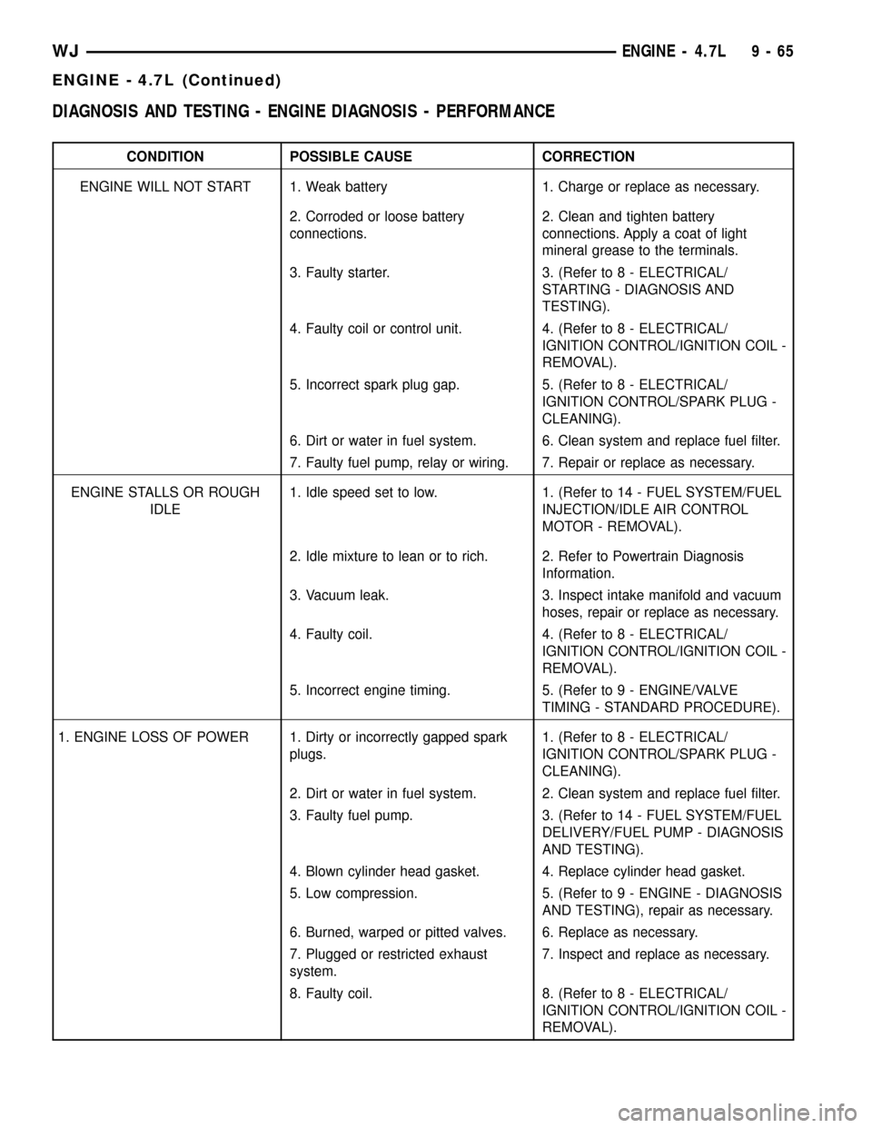
DIAGNOSIS AND TESTING - ENGINE DIAGNOSIS - PERFORMANCE
CONDITION POSSIBLE CAUSE CORRECTION
ENGINE WILL NOT START 1. Weak battery 1. Charge or replace as necessary.
2. Corroded or loose battery
connections.2. Clean and tighten battery
connections. Apply a coat of light
mineral grease to the terminals.
3. Faulty starter. 3. (Refer to 8 - ELECTRICAL/
STARTING - DIAGNOSIS AND
TESTING).
4. Faulty coil or control unit. 4. (Refer to 8 - ELECTRICAL/
IGNITION CONTROL/IGNITION COIL -
REMOVAL).
5. Incorrect spark plug gap. 5. (Refer to 8 - ELECTRICAL/
IGNITION CONTROL/SPARK PLUG -
CLEANING).
6. Dirt or water in fuel system. 6. Clean system and replace fuel filter.
7. Faulty fuel pump, relay or wiring. 7. Repair or replace as necessary.
ENGINE STALLS OR ROUGH
IDLE1. Idle speed set to low. 1. (Refer to 14 - FUEL SYSTEM/FUEL
INJECTION/IDLE AIR CONTROL
MOTOR - REMOVAL).
2. Idle mixture to lean or to rich. 2. Refer to Powertrain Diagnosis
Information.
3. Vacuum leak. 3. Inspect intake manifold and vacuum
hoses, repair or replace as necessary.
4. Faulty coil. 4. (Refer to 8 - ELECTRICAL/
IGNITION CONTROL/IGNITION COIL -
REMOVAL).
5. Incorrect engine timing. 5. (Refer to 9 - ENGINE/VALVE
TIMING - STANDARD PROCEDURE).
1. ENGINE LOSS OF POWER 1. Dirty or incorrectly gapped spark
plugs.1. (Refer to 8 - ELECTRICAL/
IGNITION CONTROL/SPARK PLUG -
CLEANING).
2. Dirt or water in fuel system. 2. Clean system and replace fuel filter.
3. Faulty fuel pump. 3. (Refer to 14 - FUEL SYSTEM/FUEL
DELIVERY/FUEL PUMP - DIAGNOSIS
AND TESTING).
4. Blown cylinder head gasket. 4. Replace cylinder head gasket.
5. Low compression. 5. (Refer to 9 - ENGINE - DIAGNOSIS
AND TESTING), repair as necessary.
6. Burned, warped or pitted valves. 6. Replace as necessary.
7. Plugged or restricted exhaust
system.7. Inspect and replace as necessary.
8. Faulty coil. 8. (Refer to 8 - ELECTRICAL/
IGNITION CONTROL/IGNITION COIL -
REMOVAL).
WJENGINE - 4.7L 9 - 65
ENGINE - 4.7L (Continued)
Page 1311 of 2199
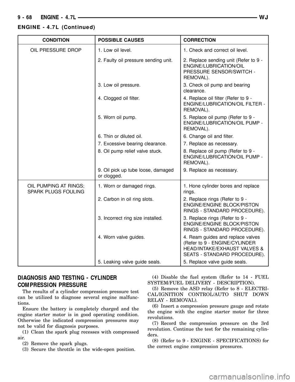
CONDITION POSSIBLE CAUSES CORRECTION
OIL PRESSURE DROP 1. Low oil level. 1. Check and correct oil level.
2. Faulty oil pressure sending unit. 2. Replace sending unit (Refer to 9 -
ENGINE/LUBRICATION/OIL
PRESSURE SENSOR/SWITCH -
REMOVAL).
3. Low oil pressure. 3. Check oil pump and bearing
clearance.
4. Clogged oil filter. 4. Replace oil filter (Refer to 9 -
ENGINE/LUBRICATION/OIL FILTER -
REMOVAL).
5. Worn oil pump. 5. Replace oil pump (Refer to 9 -
ENGINE/LUBRICATION/OIL PUMP -
REMOVAL).
6. Thin or diluted oil. 6. Change oil and filter.
7. Excessive bearing clearance. 7. Replace as necessary.
8. Oil pump relief valve stuck. 8. Replace oil pump (Refer to 9 -
ENGINE/LUBRICATION/OIL PUMP -
REMOVAL).
9. Oil pick up tube loose, damaged
or clogged.9. Replace as necessary.
OIL PUMPING AT RINGS;
SPARK PLUGS FOULING1. Worn or damaged rings. 1. Hone cylinder bores and replace
rings.
2. Carbon in oil ring slots. 2. Replace rings (Refer to 9 -
ENGINE/ENGINE BLOCK/PISTON
RINGS - STANDARD PROCEDURE).
3. Incorrect ring size installed. 3. Replace rings (Refer to 9 -
ENGINE/ENGINE BLOCK/PISTON
RINGS - STANDARD PROCEDURE).
4. Worn valve guides. 4. Ream guides and replace valves
(Refer to 9 - ENGINE/CYLINDER
HEAD/INTAKE/EXHAUST VALVES &
SEATS - STANDARD PROCEDURE).
5. Leaking valve guide seals. 5. Replace valve guide seals.
DIAGNOSIS AND TESTING - CYLINDER
COMPRESSION PRESSURE
The results of a cylinder compression pressure test
can be utilized to diagnose several engine malfunc-
tions.
Ensure the battery is completely charged and the
engine starter motor is in good operating condition.
Otherwise the indicated compression pressures may
not be valid for diagnosis purposes.
(1) Clean the spark plug recesses with compressed
air.
(2) Remove the spark plugs.
(3) Secure the throttle in the wide-open position.(4) Disable the fuel system (Refer to 14 - FUEL
SYSTEM/FUEL DELIVERY - DESCRIPTION).
(5) Remove the ASD relay (Refer to 8 - ELECTRI-
CAL/IGNITION CONTROL/AUTO SHUT DOWN
RELAY - REMOVAL).
(6) Insert a compression pressure gauge and rotate
the engine with the engine starter motor for three
revolutions.
(7) Record the compression pressure on the 3rd
revolution. Continue the test for the remaining cylin-
ders.
(8) (Refer to 9 - ENGINE - SPECIFICATIONS) for
the correct engine compression pressures.
9 - 68 ENGINE - 4.7LWJ
ENGINE - 4.7L (Continued)
Page 1315 of 2199

(13) Disconnect the engine block heater power
cable from the block heater.
(14) Lower vehicle.
(15) Remove throttle body resonator assembly and
inlet hose.
(16) Disconnect throttle and speed control cables.
(17) Disconnect tube from both the left and right
side crankcase breathers, then remove the breathers
(Fig. 5).
(18) Discharge A/C system (Refer to 24 - HEAT-
ING & AIR CONDITIONING/PLUMBING - STAN-
DARD PROCEDURE).(19) Remove radiator fan (Refer to 7 - COOLING/
ENGINE/RADIATOR FAN - REMOVAL) and acces-
sory drive belt (Refer to 7 - COOLING/ACCESSORY
DRIVE/DRIVE BELTS - REMOVAL).
(20) Remove A/C compressor (Refer to 24 - HEAT-
ING & AIR CONDITIONING/PLUMBING/A/C COM-
PRESSOR - REMOVAL).
(21) Disconnect transmission oil cooler lines at the
radiator.
(22) Disconnect radiator lower hose at the thermo-
stat housing.
(23) Remove A/C condenser (Refer to 24 - HEAT-
ING & AIR CONDITIONING/PLUMBING/A/C CON-
DENSER - REMOVAL).
(24) Remove radiator (Refer to 7 - COOLING/EN-
GINE/RADIATOR - REMOVAL).
(25) Remove generator (Refer to 8 - ELECTRICAL/
CHARGING/GENERATOR - REMOVAL).
(26) Disconnect the two heater hoses from the tim-
ing chain cover.
(27) Disconnect engine harness at the following
points :
²Intake air temperature (IAT) sensor (Fig. 6)
²Fuel Injectors
²Throttle Position (TPS) Switch
²Idle Air Control (IAC) Motor
²Engine Oil Pressure Switch
²Engine Coolant Temperature (ECT) Sensor
²Manifold absolute pressure (MAP) Sensor
²Camshaft Position (CMP) Sensor
²Coil Over Plugs
(28) Release fuel rail pressure (Refer to 14 - FUEL
SYSTEM/FUEL DELIVERY - STANDARD PROCE-
DURE) then disconnect the fuel supply quick connect
fitting at the fuel rail (Refer to 14 - FUEL SYSTEM/
FUEL DELIVERY/QUICK CONNECT FITTING -
STANDARD PROCEDURE).
(29) Remove power steering pump and position out
of the way.
(30) Disconnect ground straps from the left side of
the engine.
(31) Install Engine Lifting Fixture Special Tool
8347 (Fig. 7)following these steps.
²Holding the lifting fixture at a slight angle, slide
the large bore in the front plate over the hex portion
of the lifting stud.
²Position the two remaining fixture arms onto
the two lifting studs in the cylinder heads.
²Pull foward and upward on the lifting fixture so
that the lifting stud rest in the slotted area below the
large bore.
²Secure the lifting fixture to the three studs
using three 7/16 ± 14 N/C locknuts.
²Make sure the lifting loop in the lifting fixture is
in the last hole (closest to the throttle body) to min-
imize the angle of engine during removal.
Fig. 4 Crankshaft Position Sensor
1 - CRANKSHAFT POSITION SENSOR
2 - CYLINDER HEAD COVER
3 - CAMSHAFT POSITION SENSOR
4 - RIGHT SIDE CYLINDER BLOCK
Fig. 5 Crankcase Breather Connection Points
1 - CRANKCASE BREATHERS
9 - 72 ENGINE - 4.7LWJ
ENGINE - 4.7L (Continued)
Page 1317 of 2199
²Camshaft Position (CMP) Sensor
²Coil Over Plugs
(10) Install generator (Refer to 8 - ELECTRICAL/
CHARGING/GENERATOR - INSTALLATION).
(11) Install radiator (Refer to 7 - COOLING/EN-
GINE/RADIATOR - INSTALLATION).
(12) Install A/C condenser (Refer to 24 - HEATING
& AIR CONDITIONING/PLUMBING/A/C CON-
DENSER - INSTALLATION).
(13) Connect radiator lower hose at the thermostat
housing.
(14) Connect the transmission oil cooler lines to
the radiator.
(15) Install A/C compressor. (Refer to 24 - HEAT-
ING & AIR CONDITIONING/PLUMBING/A/C COM-
PRESSOR - INSTALLATION).
(16) Install accessory drive belt (Refer to 7 -
COOLING/ACCESSORY DRIVE/DRIVE BELTS -
INSTALLATION) and radiator fan (Refer to 7 -
COOLING/ENGINE/RADIATOR FAN - INSTALLA-
TION).
(17) Install breathers, then connect tube to both
crankcase breathers (Fig. 5).
(18) Connect throttle and speed control cables.
(19) Install throttle body resonator assembly and
inlet hose.
(20) Raise vehicle.
(21) Connect two ground straps on the lower left
hand side of the engine and one ground strap on the
lower right side.
(22) Install torque converter bolts.
(23) Connect crankshaft position sensor (Fig. 4).
(24) Install starter.
(25) Install rubber splash shield.
CAUTION: The structural cover requires a specific
torque sequence. Failure to follow this sequence
may cause severe damage to the cover.
(26) Install structural cover (Refer to 9 - ENGINE/
ENGINE BLOCK/STRUCTURAL COVER - INSTAL-
LATION).
(27) Install exhaust crossover pipe.
(28) Install engine block heater power cable, If
equipped.
(29) Lower vehicle.
(30) Check and fill engine oil (Refer to LUBRICA-
TION & MAINTENANCE/FLUID TYPES - SPECIFI-
CATIONS).
(31) Recharge the A/C system (Refer to 24 - HEAT-
ING & AIR CONDITIONING/PLUMBING - STAN-
DARD PROCEDURE).
(32) Refill the engine cooling system (Refer to 7 -
COOLING - STANDARD PROCEDURE).
(33) Connect the battery negative cable.
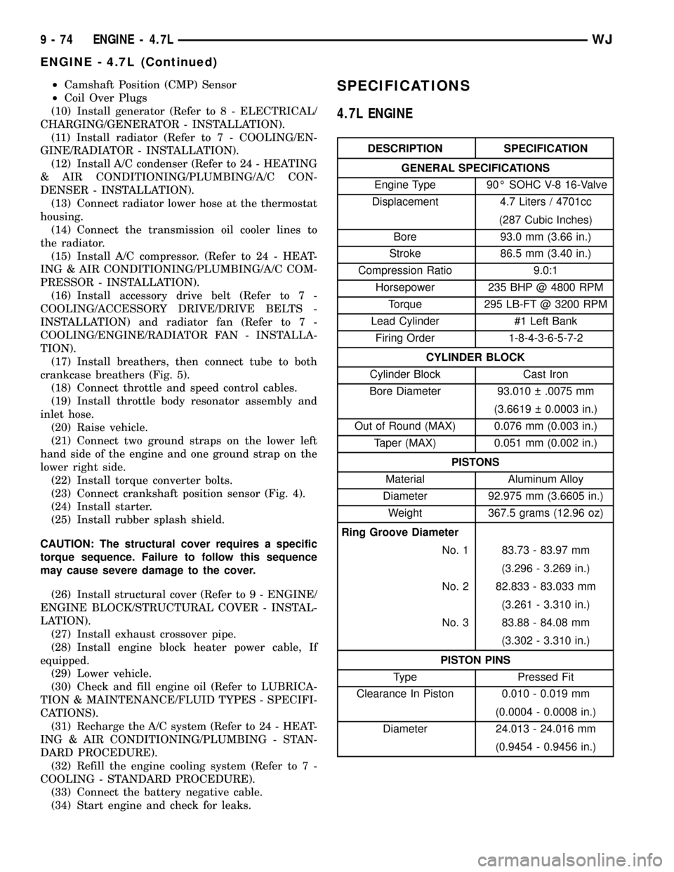
(34) Start engine and check for leaks.SPECIFICATIONS
4.7L ENGINE
DESCRIPTION SPECIFICATION
GENERAL SPECIFICATIONS
Engine Type 90É SOHC V-8 16-Valve
Displacement 4.7 Liters / 4701cc
(287 Cubic Inches)
Bore 93.0 mm (3.66 in.)
Stroke 86.5 mm (3.40 in.)
Compression Ratio 9.0:1
Horsepower 235 BHP @ 4800 RPM
Torque 295 LB-FT @ 3200 RPM
Lead Cylinder #1 Left Bank
Firing Order 1-8-4-3-6-5-7-2
CYLINDER BLOCK
Cylinder Block Cast Iron
Bore Diameter 93.010 .0075 mm
(3.6619 0.0003 in.)
Out of Round (MAX) 0.076 mm (0.003 in.)
Taper (MAX) 0.051 mm (0.002 in.)
PISTONS
Material Aluminum Alloy
Diameter 92.975 mm (3.6605 in.)
Weight 367.5 grams (12.96 oz)
Ring Groove Diameter
No. 1 83.73 - 83.97 mm
(3.296 - 3.269 in.)
No. 2 82.833 - 83.033 mm
(3.261 - 3.310 in.)
No. 3 83.88 - 84.08 mm
(3.302 - 3.310 in.)
PISTON PINS
Type Pressed Fit
Clearance In Piston 0.010 - 0.019 mm
(0.0004 - 0.0008 in.)
Diameter 24.013 - 24.016 mm
(0.9454 - 0.9456 in.)
9 - 74 ENGINE - 4.7LWJ
ENGINE - 4.7L (Continued)