2003 JEEP GRAND CHEROKEE Intake
[x] Cancel search: IntakePage 1348 of 2199
STANDARD PROCEDUREÐREFACING
NOTE: Valve seats that are worn or burned can be
reworked, provided that correct angle and seat
width are maintained. Otherwise the cylinder head
must be replaced.
NOTE: When refacing valves and valve seats, it is
important that the correct size valve guide pilot be
used for reseating stones. A true and complete sur-
face must be obtained.
(1) Using a suitable dial indicator measure the
center of the valve seat Total run out must not
exceed 0.051 mm (0.002 in).
(2) Apply a small amount of Prussian blue to the
valve seat, insert the valve into the cylinder head,
while applying light pressure on the valve rotate the
valve. Remove the valve and examine the valve face.
If the blue is transferred below the top edge of the
valve face, lower the valve seat using a 15 degree
stone. If the blue is transferred to the bottom edge of
the valve face, raise the valve seat using a 65 degree
stone.
(3) When the seat is properly positioned the width
of the intake seat must be 1.75 ± 2.36 mm (0.0689 ±
0.0928 in.) and the exhaust seat must be 1.71 ± 2.32
mm (0.0673 ± 0.0911 in.).
(4) Check the valve spring installed height after
refacing the valve and seat. The installed height for
both intake and exhaust valve springs must not
exceed 41.44 mm (1.6315 in.).
(5) The valve seat and valve face must maintain a
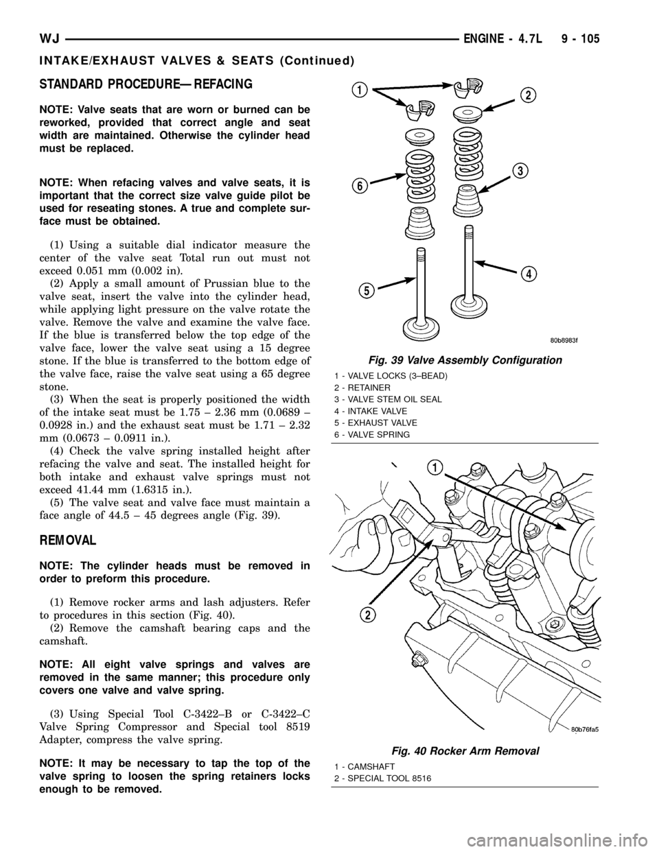
face angle of 44.5 ± 45 degrees angle (Fig. 39).
REMOVAL
NOTE: The cylinder heads must be removed in
order to preform this procedure.
(1) Remove rocker arms and lash adjusters. Refer
to procedures in this section (Fig. 40).
(2) Remove the camshaft bearing caps and the
camshaft.
NOTE: All eight valve springs and valves are
removed in the same manner; this procedure only
covers one valve and valve spring.
(3) Using Special Tool C-3422±B or C-3422±C
Valve Spring Compressor and Special tool 8519
Adapter, compress the valve spring.
NOTE: It may be necessary to tap the top of the
valve spring to loosen the spring retainers locks
enough to be removed.
Fig. 39 Valve Assembly Configuration
1 - VALVE LOCKS (3±BEAD)
2 - RETAINER
3 - VALVE STEM OIL SEAL
4 - INTAKE VALVE
5 - EXHAUST VALVE
6 - VALVE SPRING
Fig. 40 Rocker Arm Removal
1 - CAMSHAFT
2 - SPECIAL TOOL 8516
WJENGINE - 4.7L 9 - 105
INTAKE/EXHAUST VALVES & SEATS (Continued)
Page 1349 of 2199
(4) Remove the two spring retainer lock halves.
NOTE: the valve spring is under tension use care
when releasing the valve spring compressor.
(5) Remove the valve spring compressor.
(6) Remove the spring retainer, and the spring.
NOTE: Check for sharp edges on the keeper
grooves. Remove any burrs from the valve stem
before removing the valve from the cylinder head.
(7) Remove the valve from the cylinder head.
NOTE: The valve stem seals are common between
intake and exhaust.
(8) Remove the valve stem seal. Mark the valve for
proper installation.
TESTING VALVE SPRINGS
NOTE: Whenever the valves are removed from the
cylinder head it is recommended that the valve
springs be inspected and tested for reuse.
Inspect the valve springs for physical signs of wear
or damage. Turn table of tool C-647 until surface is
in line with the 40.69 mm (1.602 in.) mark on the
threaded stud and the zero mark on the front. Place
spring over the stud on the table and lift compress-
ing lever to set tone device. Pull on torque wrench
until Ping is heard. Take reading on torque wrench
at this instant. Multiply this reading by two. This
will give the spring load at test length. Fractional
measurements are indicated on the table for finer
adjustments. Refer to Specifications Section to obtain
specified height and allowable tensions. Replace any
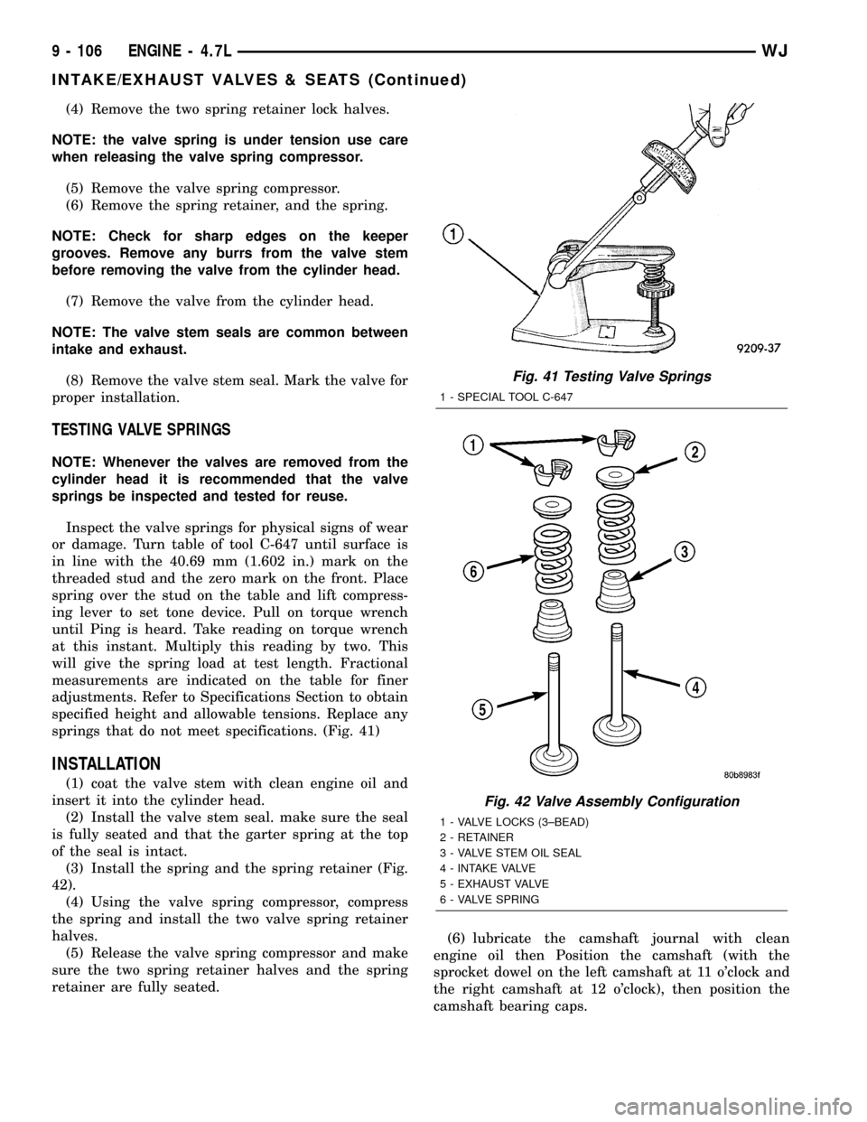
springs that do not meet specifications. (Fig. 41)
INSTALLATION
(1) coat the valve stem with clean engine oil and
insert it into the cylinder head.
(2) Install the valve stem seal. make sure the seal
is fully seated and that the garter spring at the top
of the seal is intact.
(3) Install the spring and the spring retainer (Fig.
42).
(4) Using the valve spring compressor, compress
the spring and install the two valve spring retainer
halves.
(5) Release the valve spring compressor and make
sure the two spring retainer halves and the spring
retainer are fully seated.(6) lubricate the camshaft journal with clean
engine oil then Position the camshaft (with the
sprocket dowel on the left camshaft at 11 o'clock and
the right camshaft at 12 o'clock), then position the
camshaft bearing caps.
Fig. 41 Testing Valve Springs
1 - SPECIAL TOOL C-647
Fig. 42 Valve Assembly Configuration
1 - VALVE LOCKS (3±BEAD)
2 - RETAINER
3 - VALVE STEM OIL SEAL
4 - INTAKE VALVE
5 - EXHAUST VALVE
6 - VALVE SPRING
9 - 106 ENGINE - 4.7LWJ
INTAKE/EXHAUST VALVES & SEATS (Continued)
Page 1350 of 2199
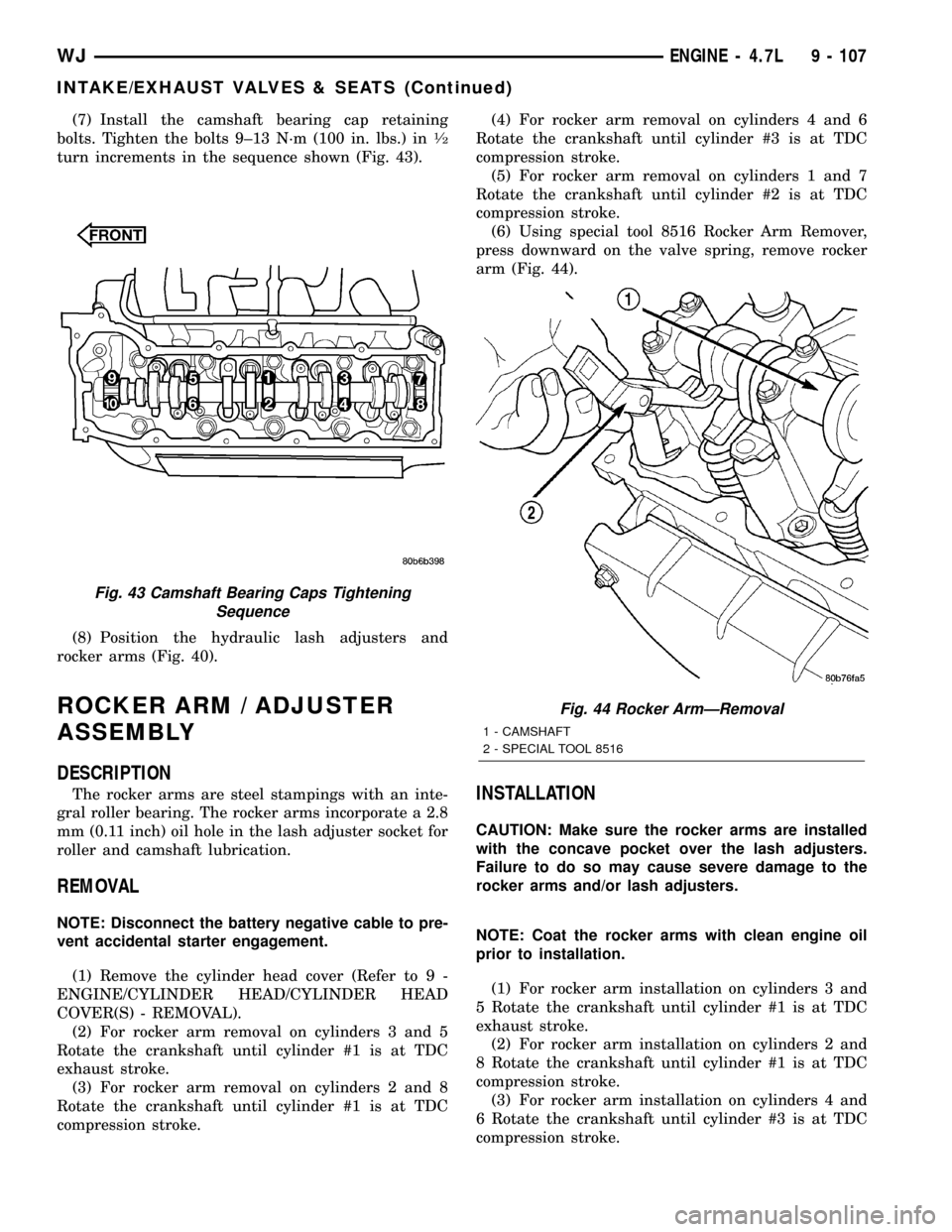
(7) Install the camshaft bearing cap retaining
bolts. Tighten the bolts 9±13 N´m (100 in. lbs.) in1¤2
turn increments in the sequence shown (Fig. 43).
(8) Position the hydraulic lash adjusters and
rocker arms (Fig. 40).
ROCKER ARM / ADJUSTER
ASSEMBLY
DESCRIPTION
The rocker arms are steel stampings with an inte-
gral roller bearing. The rocker arms incorporate a 2.8
mm (0.11 inch) oil hole in the lash adjuster socket for
roller and camshaft lubrication.
REMOVAL
NOTE: Disconnect the battery negative cable to pre-
vent accidental starter engagement.
(1) Remove the cylinder head cover (Refer to 9 -
ENGINE/CYLINDER HEAD/CYLINDER HEAD
COVER(S) - REMOVAL).
(2) For rocker arm removal on cylinders 3 and 5
Rotate the crankshaft until cylinder #1 is at TDC
exhaust stroke.
(3) For rocker arm removal on cylinders 2 and 8
Rotate the crankshaft until cylinder #1 is at TDC
compression stroke.(4) For rocker arm removal on cylinders 4 and 6
Rotate the crankshaft until cylinder #3 is at TDC
compression stroke.
(5) For rocker arm removal on cylinders 1 and 7
Rotate the crankshaft until cylinder #2 is at TDC
compression stroke.
(6) Using special tool 8516 Rocker Arm Remover,
press downward on the valve spring, remove rocker
arm (Fig. 44).
INSTALLATION
CAUTION: Make sure the rocker arms are installed
with the concave pocket over the lash adjusters.
Failure to do so may cause severe damage to the
rocker arms and/or lash adjusters.
NOTE: Coat the rocker arms with clean engine oil
prior to installation.
(1) For rocker arm installation on cylinders 3 and
5 Rotate the crankshaft until cylinder #1 is at TDC
exhaust stroke.
(2) For rocker arm installation on cylinders 2 and
8 Rotate the crankshaft until cylinder #1 is at TDC
compression stroke.
(3) For rocker arm installation on cylinders 4 and
6 Rotate the crankshaft until cylinder #3 is at TDC
compression stroke.
Fig. 43 Camshaft Bearing Caps Tightening
Sequence
Fig. 44 Rocker ArmÐRemoval
1 - CAMSHAFT
2 - SPECIAL TOOL 8516
WJENGINE - 4.7L 9 - 107
INTAKE/EXHAUST VALVES & SEATS (Continued)
Page 1351 of 2199
(4) For rocker arm installation on cylinders 1 and
7 Rotate the crankshaft until cylinder #2 is at TDC
compression stroke.
(5) Using special tool 8516 press downward on the
valve spring, install rocker arm (Fig. 44).
(6) Install the cylinder head cover (Refer to 9 -
ENGINE/CYLINDER HEAD/CYLINDER HEAD
COVER(S) - INSTALLATION).
VALVE SPRINGS
DESCRIPTION
The valve springs are made from high strength
chrome silicon steel. The springs are common for
intake and exhaust applications. The valve spring
seat is integral with the valve stem seal, which is a
positive type seal to control lubrication.
VALVE STEM SEALS
DESCRIPTION
The valve stem seals are made of rubber and incor-
porate an integral steel valve spring seat. The inte-
gral garter spring maintains consistent lubrication
control to the valve stems.
ENGINE BLOCK
DESCRIPTION
The cylinder block is made of cast iron. The block
is a closed deck design with the left bank forward. To
provide high rigidity and improved NVH an
enhanced compacted graphite bedplate is bolted to
the block. The block design allows coolant flow
between the cylinders bores, and an internal coolant
bypass to a single poppet inlet thermostat is included
in the cast aluminum front cover.
STANDARD PROCEDUREÐCYLINDER BORE
HONING
Before honing, stuff plenty of clean shop towels
under the bores and over the crankshaft to keep
abrasive materials from entering the crankshaft
area.
(1) Used carefully, the Cylinder Bore Sizing Hone
C-823, equipped with 220 grit stones, is the best tool
for this job. In addition to deglazing, it will reduce
taper and out-of-round, as well as removing light
scuffing, scoring and scratches. Usually, a few strokes
will clean up a bore and maintain the required lim-
its.CAUTION: DO NOT use rigid type hones to remove
cylinder wall glaze.
(2) Deglazing of the cylinder walls may be done if
the cylinder bore is straight and round. Use a cylin-
der surfacing hone, Honing Tool C-3501, equipped
with 280 grit stones (C-3501-3810). about 20-60
strokes, depending on the bore condition, will be suf-
ficient to provide a satisfactory surface. Using honing
oil C-3501-3880, or a light honing oil, available from
major oil distributors.
CAUTION: DO NOT use engine or transmission oil,
mineral spirits, or kerosene.
(3) Honing should be done by moving the hone up
and down fast enough to get a crosshatch pattern.
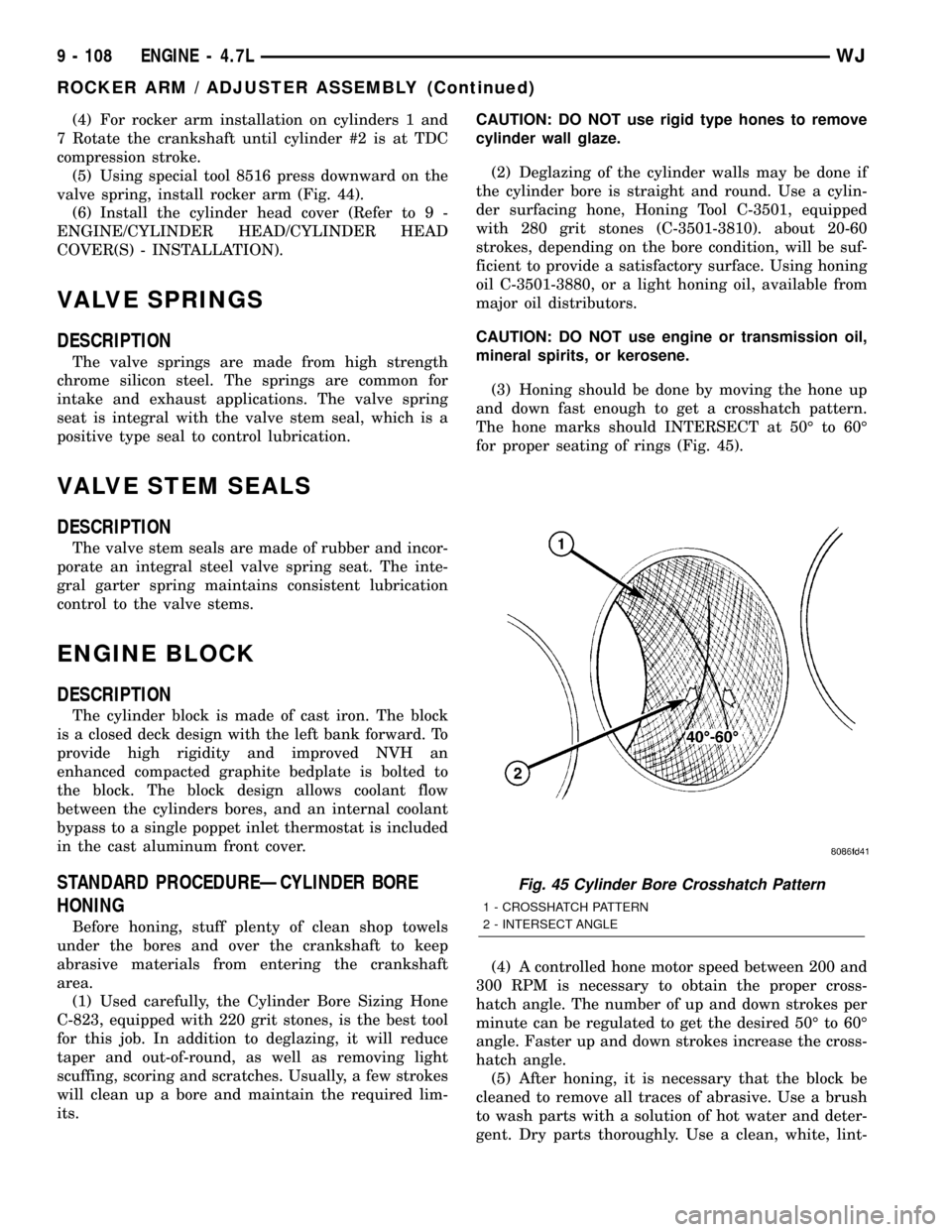
The hone marks should INTERSECT at 50É to 60É
for proper seating of rings (Fig. 45).
(4) A controlled hone motor speed between 200 and
300 RPM is necessary to obtain the proper cross-
hatch angle. The number of up and down strokes per
minute can be regulated to get the desired 50É to 60É
angle. Faster up and down strokes increase the cross-
hatch angle.
(5) After honing, it is necessary that the block be
cleaned to remove all traces of abrasive. Use a brush
to wash parts with a solution of hot water and deter-
gent. Dry parts thoroughly. Use a clean, white, lint-
Fig. 45 Cylinder Bore Crosshatch Pattern
1 - CROSSHATCH PATTERN
2 - INTERSECT ANGLE
9 - 108 ENGINE - 4.7LWJ
ROCKER ARM / ADJUSTER ASSEMBLY (Continued)
Page 1369 of 2199
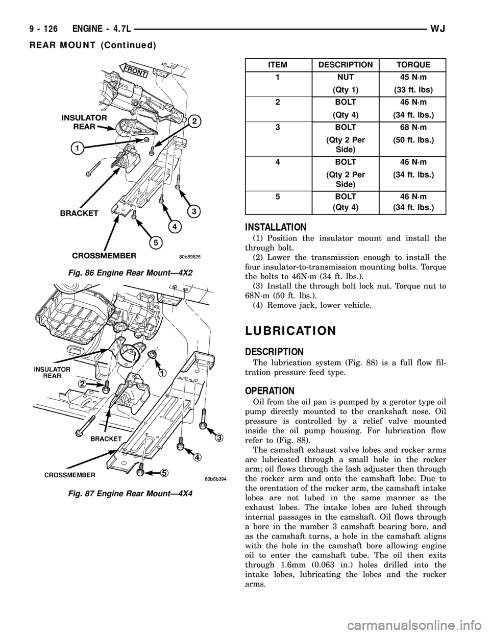
ITEM DESCRIPTION TORQUE
1 NUT 45 N´m
(Qty 1) (33 ft. lbs)
2 BOLT 46 N´m
(Qty 4) (34 ft. lbs.)
3 BOLT 68 N´m
(Qty 2 Per
Side)(50 ft. lbs.)
4 BOLT 46 N´m
(Qty 2 Per
Side)(34 ft. lbs.)
5 BOLT 46 N´m
(Qty 4) (34 ft. lbs.)
INSTALLATION
(1) Position the insulator mount and install the
through bolt.
(2) Lower the transmission enough to install the
four insulator-to-transmission mounting bolts. Torque
the bolts to 46N´m (34 ft. lbs.).
(3) Install the through bolt lock nut. Torque nut to
68N´m (50 ft. lbs.).
(4) Remove jack, lower vehicle.
LUBRICATION
DESCRIPTION
The lubrication system (Fig. 88) is a full flow fil-
tration pressure feed type.
OPERATION
Oil from the oil pan is pumped by a gerotor type oil
pump directly mounted to the crankshaft nose. Oil
pressure is controlled by a relief valve mounted
inside the oil pump housing. For lubrication flow
refer to (Fig. 88).
The camshaft exhaust valve lobes and rocker arms
are lubricated through a small hole in the rocker
arm; oil flows through the lash adjuster then through
the rocker arm and onto the camshaft lobe. Due to
the orentation of the rocker arm, the camshaft intake
lobes are not lubed in the same manner as the
exhaust lobes. The intake lobes are lubed through
internal passages in the camshaft. Oil flows through
a bore in the number 3 camshaft bearing bore, and
as the camshaft turns, a hole in the camshaft aligns
with the hole in the camshaft bore allowing engine
oil to enter the camshaft tube. The oil then exits
through 1.6mm (0.063 in.) holes drilled into the
intake lobes, lubricating the lobes and the rocker
arms.
Fig. 86 Engine Rear MountÐ4X2
Fig. 87 Engine Rear MountÐ4X4
9 - 126 ENGINE - 4.7LWJ
REAR MOUNT (Continued)
Page 1371 of 2199
ENGINE LUBRICATION FLOW CHARTÐBLOCK: TABLE 1
FROM TO
Oil Pickup Tube Oil Pump
Oil Pump Oil Filter
Oil Filter Block Main Oil Gallery
Block Main Oil Gallery 1. Crankshaft Main Journal
2. Left Cylinder Head*
3. Right Cylinder Head*
Crankshaft Main Journals Crankshaft Rod Journals
Crankshaft Number One Main Journal 1.Front Timing Chain Idler Shaft
2.Both Secondary Chain Tensioners
Left Cylinder Head See Table 2
Right Cylinder Head See Table 2
* The cylinder head
gaskets have an oil restricter to control oil flow to the cylinder heads.
ENGINE LUBRICATION FLOW CHARTÐCYLINDER HEADS: TABLE 2
FROM TO
Cylinder Head Oil Port (in bolt hole) Diagonal Cross Drilling to Main Oil Gallery
Main Oil Gallery (drilled through head from rear to
front)1. Base of Camshaft Towers
2. Lash Adjuster Towers
Base of Camshaft Towers Vertical Drilling Through Tower to Camshaft Bearings**
Lash Adjuster Towers Diagonal Drillings to Hydraulic Lash Adjuster Pockets
** The number three camshaft bearing journal feeds oil into the hollow camshaft tubes. Oil is routed to the intake
lobes, which have oil passages drilled into them to lubricate the rocker arms.
DIAGNOSIS AND TESTING
DIAGNOSIS AND TESTINGÐENGINE OIL
PRESSURE
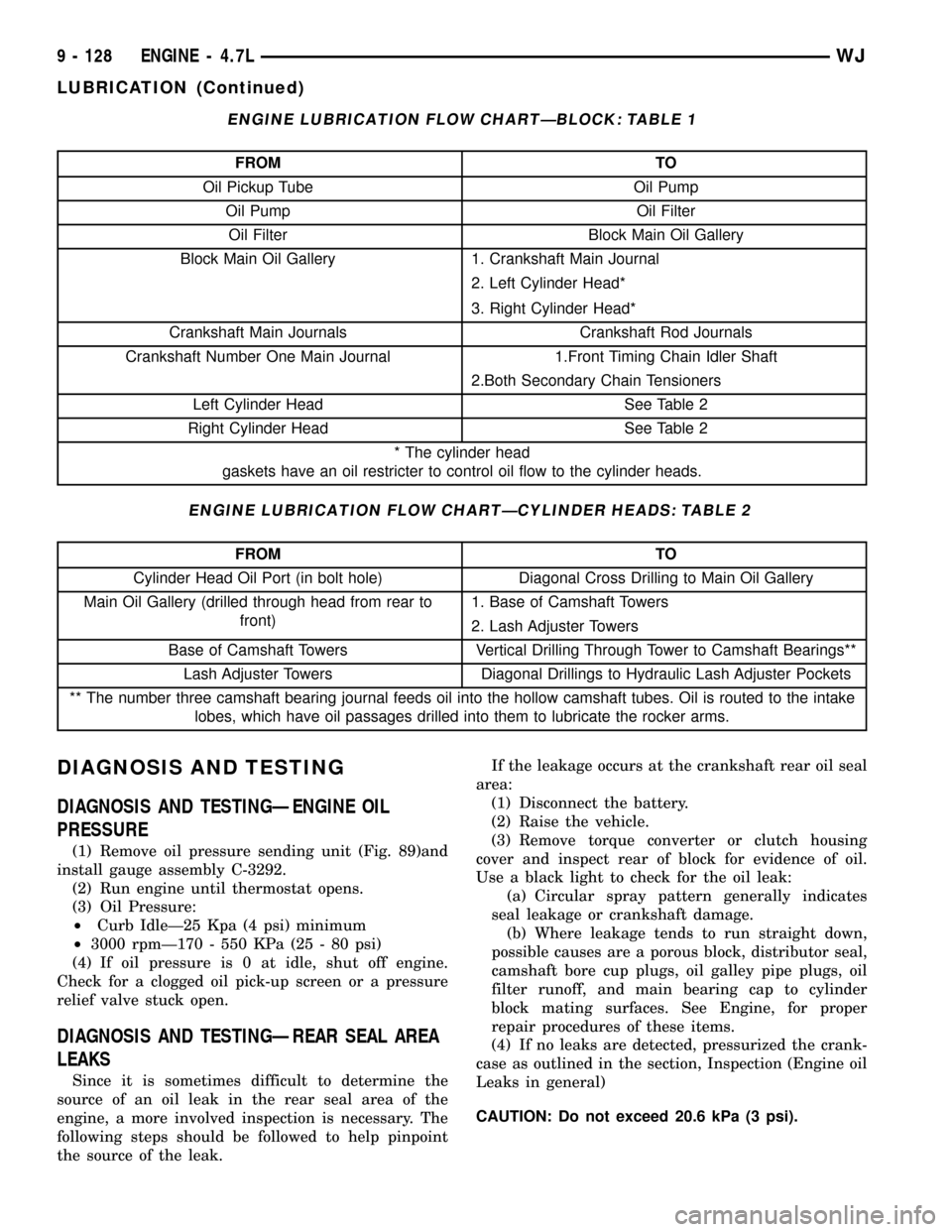
(1) Remove oil pressure sending unit (Fig. 89)and
install gauge assembly C-3292.
(2) Run engine until thermostat opens.
(3) Oil Pressure:
²Curb IdleÐ25 Kpa (4 psi) minimum
²3000 rpmÐ170 - 550 KPa (25 - 80 psi)
(4) If oil pressure is 0 at idle, shut off engine.
Check for a clogged oil pick-up screen or a pressure
relief valve stuck open.
DIAGNOSIS AND TESTINGÐREAR SEAL AREA
LEAKS
Since it is sometimes difficult to determine the
source of an oil leak in the rear seal area of the
engine, a more involved inspection is necessary. The
following steps should be followed to help pinpoint
the source of the leak.If the leakage occurs at the crankshaft rear oil seal
area:
(1) Disconnect the battery.
(2) Raise the vehicle.
(3) Remove torque converter or clutch housing
cover and inspect rear of block for evidence of oil.
Use a black light to check for the oil leak:
(a) Circular spray pattern generally indicates
seal leakage or crankshaft damage.
(b) Where leakage tends to run straight down,
possible causes are a porous block, distributor seal,
camshaft bore cup plugs, oil galley pipe plugs, oil
filter runoff, and main bearing cap to cylinder
block mating surfaces. See Engine, for proper
repair procedures of these items.
(4) If no leaks are detected, pressurized the crank-
case as outlined in the section, Inspection (Engine oil
Leaks in general)
CAUTION: Do not exceed 20.6 kPa (3 psi).
9 - 128 ENGINE - 4.7LWJ
LUBRICATION (Continued)
Page 1379 of 2199
INTAKE MANIFOLD
DESCRIPTION
The intake manifold is made of a composite mate-
rial and features long runners which maximizes low
end torque. The intake manifold uses single plane
sealing which consist of eight individual press in
place port gaskets to prevent leaks. Eight studs and
two bolts are used to fasten the intake to the head.
DIAGNOSIS AND TESTINGÐINTAKE
MANIFOLD LEAKAGE
An intake manifold air leak is characterized by
lower than normal manifold vacuum. Also, one or
more cylinders may not be functioning.
WARNING: USE EXTREME CAUTION WHEN THE
ENGINE IS OPERATING. DO NOT STAND IN A
DIRECT LINE WITH THE FAN. DO NOT PUT YOUR
HANDS NEAR THE PULLEYS, BELTS OR THE FAN.
DO NOT WEAR LOOSE CLOTHING.
(1) Start the engine.
(2) Spray a small stream of water at the suspected
leak area.
(3) If a change in RPM is observed the area of the
suspected leak has been found.
(4) Repair as required.
REMOVAL
(1) Disconnect negative cable from battery.
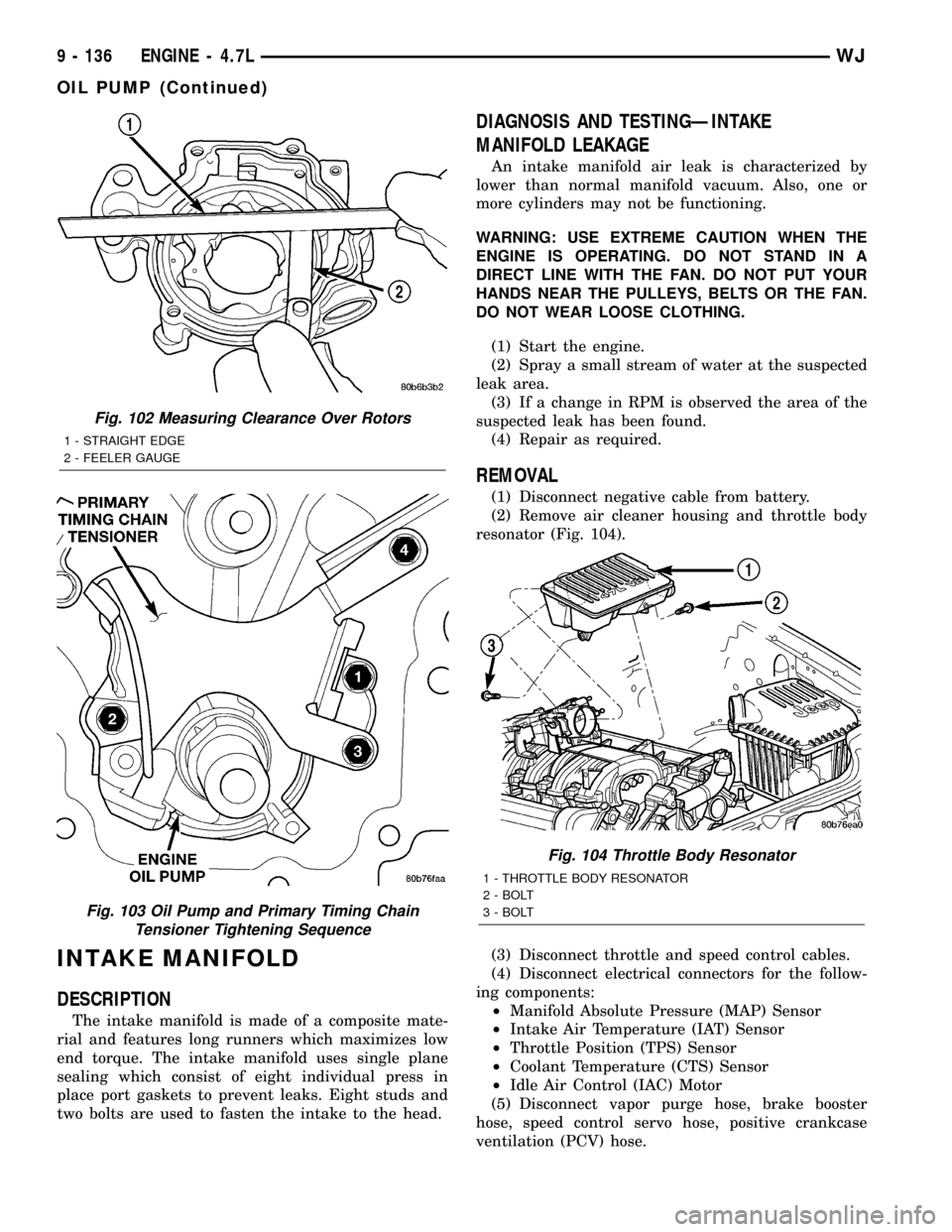
(2) Remove air cleaner housing and throttle body
resonator (Fig. 104).
(3) Disconnect throttle and speed control cables.
(4) Disconnect electrical connectors for the follow-
ing components:
²Manifold Absolute Pressure (MAP) Sensor
²Intake Air Temperature (IAT) Sensor
²Throttle Position (TPS) Sensor
²Coolant Temperature (CTS) Sensor
²Idle Air Control (IAC) Motor
(5) Disconnect vapor purge hose, brake booster
hose, speed control servo hose, positive crankcase
ventilation (PCV) hose.
Fig. 102 Measuring Clearance Over Rotors
1 - STRAIGHT EDGE
2 - FEELER GAUGE
Fig. 103 Oil Pump and Primary Timing Chain
Tensioner Tightening Sequence
Fig. 104 Throttle Body Resonator
1 - THROTTLE BODY RESONATOR
2 - BOLT
3 - BOLT
9 - 136 ENGINE - 4.7LWJ
OIL PUMP (Continued)
Page 1380 of 2199
(6) Remove accessory drive belt (Refer to 7 -
COOLING/ACCESSORY DRIVE/DRIVE BELTS -
REMOVAL).
(7) Disconnect generator electrical connections.
(8) Unbolt the generator and move it away from
the intake manifold for clearance.
(9) Disconnect air conditioning compressor electri-
cal connections.
(10) Unbolt the air conditioning compressor and
move it away from the intake manifold for clearance.
(11) Disconnect left and right radio suppressor
straps.
(12) Disconnect and remove ignition coil towers
(Refer to 8 - ELECTRICAL/IGNITION CONTROL/
IGNITION COIL - REMOVAL).
(13) Remove top oil dipstick tube retaining bolt
and ground strap.
(14) Bleed pressure from fuel system (Refer to 14 -
FUEL SYSTEM/FUEL DELIVERY - STANDARD
PROCEDURE).
(15) Remove fuel rail (Refer to 14 - FUEL SYS-
TEM/FUEL DELIVERY/FUEL RAIL - REMOVAL).
(16) Remove throttle body assembly and mounting
bracket.
(17) Drain cooling system below coolant tempera-
ture level (Refer to 7 - COOLING - STANDARD
PROCEDURE).
(18) Remove coolant temperature sensor (Refer to
7 - COOLING/ENGINE/ENGINE COOLANT TEMP
SENSOR - REMOVAL).
(19) Remove cowl to hood seal. (Refer to 23 -
BODY/WEATHERSTRIP/SEALS/COWL WEATHER-
STRIP - REMOVAL).
(20) Remove right side engine lifting stud.
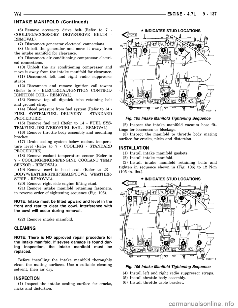
(21) Remove intake manifold retaining fasteners,
in reverse order of tightening sequence (Fig. 105).
NOTE: Intake must be lifted upward and level in the
front and rear to clear the cowl. Interference with
the cowl will occur during removal.
(22) Remove intake manifold.
CLEANING
NOTE: There is NO approved repair procedure for
the intake manifold. If severe damage is found dur-
ing inspection, the intake manifold must be
replaced.
Before installing the intake manifold thoroughly
clean the mating surfaces. Use a suitable cleaning
solvent, then air dry.
INSPECTION
(1) Inspect the intake sealing surface for cracks,
nicks and distortion.(2) Inspect the intake manifold vacuum hose fit-
tings for looseness or blockage.
(3) Inspect the manifold to throttle body mating
surface for cracks, nicks and distortion.
INSTALLATION
(1) Install intake manifold gaskets.
(2) Install intake manifold.
(3) Install intake manifold retaining bolts and
tighten in sequence shown in (Fig. 106) to 12 N´m
(105 in. lbs.).
(4) Install left and right radio suppressor straps.
(5) Install throttle body assembly.
(6) Install throttle cable bracket.
Fig. 105 Intake Manifold Tightening Sequence
Fig. 106 Intake Manifold Tightening Sequence
WJENGINE - 4.7L 9 - 137
INTAKE MANIFOLD (Continued)