2003 JEEP GRAND CHEROKEE brake pad
[x] Cancel search: brake padPage 34 of 2199

OPERATION
The coil springs control ride quality and maintain
proper ride height. The isolators provide road noise
isolation.
REMOVAL
(1) Raise and support the vehicle.
(2) Remove the wheel and tire assemblies.
(3) Position a hydraulic jack under the axle to sup-
port it.
(4) Remove shock absorbers lower mounting nuts
from the axle brackets.
(5) Remove the track bar mounting bolt from the
axle bracket.
NOTE: Make sure the lower part of the shock does
not hold tension on the brake lines at the axle tube
housing located at the lower shock mounting area.
(6) Lower the axle until the spring is free from the
upper mount and isolator (Fig. 10).
(7) Remove the spring from the vehicle.
(8) Remove and inspect the upper and lower
spring isolators.
INSTALLATION
(1) Install the upper isolator.
(2) Install the lower isolator with the isolator loca-
tor nub in the axle pad hole (Fig. 11).
(3) Position the coil spring on the axle spring pad.CAUTION: Ensure the spring is positioned on the
lower isolator with the end of the spring coil
against the isolator spring locator (Fig. 12).
(4) Raise the axle and guide the springs onto the
spring upper mounts and lower shock studs into the
axle brackets.
(5) Install the shock absorbers lower mounting
nuts.
Fig. 10 Front Coil Spring
1 - UPPER ISOLATOR
2 - COIL SPRING
3 - LOWER ISOLATOR
4 - STABILIZER LINK
Fig. 11 Lower Isolator
1 - LOCATING NUB
2 - LOWER ISOLATOR
3 - AXLE SPRING PAD
4 - LOCATING HOLE
Fig. 12 Isolator Spring Locator
1 - COIL SPRING
2 - SPRING LOCATOR
3 - LOWER ISOLATOR
WJFRONT 2 - 13
SPRING (Continued)
Page 59 of 2199

FRONT TUBE AXLE
TABLE OF CONTENTS
page page
FRONT TUBE AXLE
REMOVAL.............................14INSTALLATION.........................14
FRONT TUBE AXLE
REMOVAL
(1) Raise and support the vehicle.
(2) Position a lifting device under the axle and
secure axle to lift.
(3) Remove the wheels and tires.
(4) Remove the brake rotors (Refer to 5 - BRAKES/
HYDRAULIC/MECHANICAL/ROTORS - REMOVAL)
and calipers.
(5) Disconnect wheel sensor wiring harness from
the vehicle wiring harness.
(6) Remove stabilizer bar links at the axle.
(7) Remove shock absorbers from axle brackets.
(8) Removet track bar.
(9) Remove tie rod and drag link from the steering
knuckle.
(10) Remove steering damper from the axle
bracket.
(11) Remove upper and lower suspension arms
from the axle brackets.
(12) Lower the lift enough to remove the axle. The
coil springs will drop with the axle.
(13) Remove the coil springs from the axle.
INSTALLATION
CAUTION: The weight of the vehicle must be sup-
ported by the springs before suspension arms and
track bar fasteners are tightened. If not at their nor-mal ride position, ride height and handling could be
affected.
(1) Install springs and retainer clips and tighten
retainer bolts to 21 N´m (16 ft. lbs.).
(2) Lift and position axle under the vehicle and
align it with the spring pads.
(3) Position upper and lower suspension arms in
the axle brackets and loosely install bolts and nuts.
(4) Install track bar to the axle bracket and loosely
install bolt.
(5) Install shock absorbers and tighten bolts to 23
N´m (17 ft. lbs.).
(6) Install stabilizer bar links to the axle brackets
and tighten nuts to 95 N´m (70 ft. lbs.).
(7) Install drag link and tie rod to the steering
knuckles.
(8) Install steering damper to the axle bracket and
tighten nut to 75 N´m (55 ft. lbs.).
(9) Install the brake rotors and calipers.
(10) Connect wheel speed sensor wiring harness, if
equipped.
(11) Install the wheel and tire assemblies.
(12) Remove lift from the axle and lower the vehi-
cle.
(13) Tighten upper suspension arm nuts to 75 N´m
(55 ft. lbs.). Tighten lower suspension arm nuts to
115 N´m (85 ft. lbs.).
(14) Tighten track bar bolt at the axle bracket to
100 N´m (74 ft. lbs.).
(15) Check the front wheel alignment.
3 - 14 FRONT TUBE AXLEWJ
Page 66 of 2199

INSTALLATION
CAUTION: The weight of the vehicle must be sup-
ported by the springs before suspension arms and
track bar fasteners can be tightened. If springs are
not at their normal ride position, ride height and
handling could be affected.
(1) Install the springs and retainer clips. Tighten
the retainer bolts to 21 N´m (16 ft. lbs.).
(2) Support the axle on a lifting device and posi-
tion axle under the vehicle.
(3) Raise the axle and align it with the spring
pads.
(4) Position the upper and lower suspension arms
in the axle brackets. Loosely install bolts and nuts to
hold suspension arms to the axle brackets.
(5) Install vent hose to the axle shaft tube.
(6) Install track bar in the axle bracket and install
the bolt loosely.
(7) Install shock absorbers and tighten the bolts to
23 N´m (17 ft. lbs.).
(8) Install stabilizer bar links to the axle brackets
and tighten the nuts to 95 N´m (70 ft. lbs.).
(9) Install drag link and tie rod to the steering
knuckles.
(10) Install steering damper to the axle bracket
and tighten the nut to 75 N´m (55 ft. lbs.).
(11) Install the brake rotors (Refer to 5 - BRAKES/
HYDRAULIC/MECHANICAL/ROTORS - INSTALLA-
TION) and calipers.
(12) Connect the wheel speed sensor wiring har-
ness to the vehicle wiring harness.
(13) Align the previously made marks on the pro-
peller shaft and the yoke/pinion flange.
(14) Install propeller shaft to pinion flange bolts ,
if equipped.
(15) Install propeller shaft to yoke straps and
bolts, if equipped.
(16) Check and fill axle lubricant.
(17) Install the wheel and tire assemblies.
(18) Remove the lifting device from the axle and
lower the vehicle.
(19) Tighten the upper suspension arm nuts to 75
N´m (55 ft. lbs.). Tighten the lower suspension arm
nuts to 115 N´m (85 ft. lbs.).
(20) Tighten the track bar bolt at the axle bracket
to 100 N´m (74 ft. lbs.).
(21) Check the front wheel alignment.
ADJUSTMENTS
Ring and pinion gears are supplied as matched
sets only. The identifying numbers for the ring and
pinion gear are etched onto each gear (Fig. 3). A plus
(+) number, minus (±) number or zero (0) is etched
into the face of the pinion gear. This number is theamount (in thousandths of an inch) the depth varies
from the standard depth setting of a pinion etched
with a (0). The standard setting from the center line
of the ring gear to the back face of the pinion is 92.1
mm (3.625 in.). The standard depth provides the best
gear tooth contact pattern. Refer to Backlash and
Contact Pattern Analysis paragraph in this section
for additional information.
Compensation for pinion depth variance is
achieved with a select shim/oil slinger. The shims are
placed between the rear pinion bearing and the pin-
ion gear head (Fig. 4).
Fig. 3 PINION GEAR ID NUMBERS
1 - PRODUCTION NUMBERS
2 - DRIVE PINION GEAR DEPTH VARIANCE
3 - GEAR MATCHING NUMBER
Fig. 4 ADJUSTMENT SHIM LOCATIONS
1 - PINION DEPTH SHIM/OIL SLINGER
2 - DIFFERENTIAL BEARING SHIM
3 - RING GEAR
4 - DIFFERENTIAL BEARING SHIM
5 - COLLAPSIBLE SPACER
WJFRONT AXLE - 186FBI 3 - 21
FRONT AXLE - 186FBI (Continued)
Page 176 of 2199

BRAKES
TABLE OF CONTENTS
page page
BRAKES - BASE........................... 1BRAKES - ABS........................... 41
BRAKES - BASE
TABLE OF CONTENTS
page page
BRAKES - BASE
DESCRIPTION..........................2
DIAGNOSIS AND TESTING - BASE BRAKE
SYSTEM.............................2
STANDARD PROCEDURE
STANDARD PROCEDURE - MANUAL
BLEEDING............................5
STANDARD PROCEDURE - PRESSURE
BLEEDING............................5
SPECIFICATIONS
BRAKE COMPONENTS..................6
TORQUE CHART......................6
SPECIAL TOOLS
BASE BRAKES........................7
BRAKE FLUID LEVEL SWITCH
REMOVAL.............................7
INSTALLATION..........................7
RED BRAKE WARN INDICATOR SWITCH
DESCRIPTION..........................7
OPERATION............................7
DIAGNOSIS AND TESTING - RED BRAKE
WARNING LAMP.......................7
ADJUSTABLE PEDAL SWITCH
REMOVAL.............................8
INSTALLATION..........................8
BRAKE LINES
DESCRIPTION..........................8
DIAGNOSIS AND TESTING - BRAKE HOSES
AND LINES...........................8
STANDARD PROCEDURE
STANDARD PROCEDURE - DOUBLE
INVERTED FLARING....................9
STANDARD PROCEDURE - ISO FLARING . . . 9
BRAKE PADS / SHOES
DESCRIPTION
DESCRIPTION - FRONT DISC BRAKE
SHOES.............................10DESCRIPTION - REAR DISC BRAKE SHOES . 10
OPERATION
OPERATION - FRONT DISC BRAKE SHOES . 10
OPERATION - REAR DISC BRAKE SHOES . . 10
REMOVAL
REMOVAL- FRONT DISC BRAKE SHOES . . . 11
REMOVAL - REAR DISC BRAKE SHOES....12
INSTALLATION
INSTALLATION - FRONT DISC BRAKE
SHOES.............................13
INSTALLATION - REAR DISC BRAKE
SHOES.............................14
DISC BRAKE CALIPERS
REMOVAL
REMOVAL - FRONT DISC BRAKE CALIPER . 14
REMOVAL - REAR DISC BRAKE CALIPER . . 15
DISASSEMBLY
DISASSEMBLY - FRONT DISC BRAKE
CALIPER............................17
DISASSEMBLY - REAR DISC BRAKE
CALIPER............................18
CLEANING - DISC BRAKE CALIPER.........19
INSPECTION - DISC BRAKE CALIPER.......19
ASSEMBLY
ASSEMBLY - FRONT DISC BRAKE CALIPER . 20
ASSEMBLY - REAR DISC BRAKE CALIPER . 21
INSTALLATION
INSTALLATION - FRONT DISC BRAKE
CALIPER............................22
INSTALLATION - REAR DISC BRAKE
CALIPER............................22
FLUID
DIAGNOSIS AND TESTING - BRAKE FLUID
CONTAMINATION.....................22
SPECIFICATIONS
BRAKE FLUID........................23
FLUID RESERVOIR
REMOVAL.............................23
WJBRAKES 5 - 1
Page 183 of 2199

ADJUSTABLE PEDAL SWITCH
REMOVAL
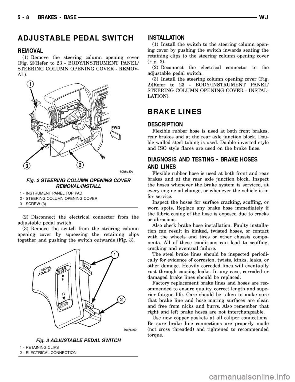
(1) Remove the steering column opening cover
(Fig. 2)(Refer to 23 - BODY/INSTRUMENT PANEL/
STEERING COLUMN OPENING COVER - REMOV-
AL).
(2) Disconnect the electrical connector from the
adjustable pedal switch.
(3) Remove the switch from the steering column
opening cover by squeezing the retaining clips
together and pushing the switch outwards (Fig. 3).
INSTALLATION
(1) Install the switch to the steering column open-
ing cover by pushing the switch inwards seating the
retaining clips to the steering column opening cover
(Fig. 3).
(2) Reconnect the electrical connector to the
adjustable pedal switch.
(3) Install the steering column opening cover (Fig.
2)(Refer to 23 - BODY/INSTRUMENT PANEL/
STEERING COLUMN OPENING COVER - INSTAL-
LATION).
BRAKE LINES
DESCRIPTION
Flexible rubber hose is used at both front brakes,
rear brakes and at the rear axle junction block. Dou-
ble walled steel tubing is used. Double inverted style
and ISO style flares are used on the brake lines.
DIAGNOSIS AND TESTING - BRAKE HOSES
AND LINES
Flexible rubber hose is used at both front and rear
brakes and at the rear axle junction block. Inspect
the hoses whenever the brake system is serviced, at
every engine oil change, or whenever the vehicle is in
for service.
Inspect the hoses for surface cracking, scuffing, or
worn spots. Replace any brake hose immediately if
the fabric casing of the hose is exposed due to cracks
or abrasions.
Also check brake hose installation. Faulty installa-
tion can result in kinked, twisted hoses, or contact
with the wheels and tires or other chassis compo-
nents. All of these conditions can lead to scuffing,
cracking and eventual failure.
The steel brake lines should be inspected periodi-
cally for evidence of corrosion, twists, kinks, leaks, or
other damage. Heavily corroded lines will eventually
rust through causing leaks. In any case, corroded or
damaged brake lines should be replaced.
Factory replacement brake lines and hoses are rec-
ommended to ensure quality, correct length and supe-
rior fatigue life. Care should be taken to make sure
that brake line and hose mating surfaces are clean
and free from nicks and burrs. Also remember that
right and left brake hoses are not interchangeable.
Use new copper gaskets at all caliper connections.
Be sure brake line connections are properly made
(not cross threaded) and tightened to recommended
torque.
Fig. 2 STEERING COLUMN OPENING COVER
REMOVAL/INSTALL
1 - INSTRUMENT PANEL TOP PAD
2 - STEERING COLUMN OPENING COVER
3 - SCREW (3)
Fig. 3 ADJUSTABLE PEDAL SWITCH
1 - RETAINING CLIPS
2 - ELECTRICAL CONNECTION
5 - 8 BRAKES - BASEWJ
Page 185 of 2199

BRAKE PADS / SHOES
DESCRIPTION
DESCRIPTION - FRONT DISC BRAKE SHOES
The calipers are twin piston type. The calipers are
free to slide laterally on the anchor, this allows con-
tinuous compensation for lining wear.
DESCRIPTION - REAR DISC BRAKE SHOES
The rear disc brakes consist of single piston float-
ing-type calipers and solid rotors. The rear caliper is
mounted on an anchor attached to an adapter
attached the rear axle tube flange. The anchors are
secured to the adapters with mounting bolts. The
disc brake rotor splash shield is part of the adaptor.
The disc brake rotor has a built in brake drum used
for the parking brakes (Fig. 6). The parking brake
shoes are mounted to the adaptor.
OPERATION
OPERATION - FRONT DISC BRAKE SHOES
When the brakes are applied fluid pressure is
exerted against the caliper pistons. The fluid pres-
sure is exerted equally and in all directions. This
means pressure exerted against the caliper pistons
and within the caliper bores will be equal (Fig. 7).
Fluid pressure applied to the pistons is transmit-
ted directly to the inboard brake shoe. This forces the
shoe lining against the inner surface of the disc
brake rotor. At the same time, fluid pressure within
the piston bores forces the caliper to slide inward on
the slide pins. This action brings the outboard brake
shoe lining into contact with the outer surface of the
disc brake rotor.
Fluid pressure acting simultaneously on the pis-
tons and caliper to produces a strong clamping
action. When sufficient force is applied, friction will
stop the rotors from turning and bring the vehicle to
a stop.Application and release of the brake pedal gener-
ates only a very slight movement of the caliper and
pistons. Upon release of the pedal, the caliper and
pistons return to a rest position. The brake shoes do
not retract an appreciable distance from the rotor. In
fact, clearance is usually at, or close to zero. The rea-
sons for this are to keep road debris from getting
between the rotor and lining and in wiping the rotor
surface clear each revolution.
The caliper piston seals control the amount of pis-
ton extension needed to compensate for normal lining
wear.
During brake application, the seals are deflected
outward by fluid pressure and piston movement (Fig.
8). When the brakes (and fluid pressure) are
released, the seals relax and retract the pistons.
The front outboard brake shoes have wear indica-
tors.
OPERATION - REAR DISC BRAKE SHOES
When the brakes are applied fluid pressure is
exerted against the caliper pistons. The fluid pres-
sure is exerted equally and in all directions. This
means pressure exerted against the caliper pistons
and within the caliper bores will be equal (Fig. 7).
Fluid pressure applied to the pistons is transmit-
ted directly to the inboard brake shoe. This forces the
Fig. 6 Rear Disc Brake Rotor
1 - PARKING BRAKE DRUM SURFACE
2 - REAR DISC BRAKE ROTOR
Fig. 7 Brake Caliper Operation
1 - CALIPER
2 - PISTON
3 - PISTON BORE
4 - SEAL
5 - INBOARD SHOE
6 - OUTBOARD SHOE
5 - 10 BRAKES - BASEWJ
Page 186 of 2199

shoe lining against the inner surface of the disc
brake rotor. At the same time, fluid pressure within
the piston bores forces the caliper to slide inward on
the slide pins. This action brings the outboard brake
shoe lining into contact with the outer surface of the
disc brake rotor.
Fluid pressure acting simultaneously on the pis-
tons and caliper to produces a strong clamping
action. When sufficient force is applied, friction will
stop the rotors from turning and bring the vehicle to
a stop.
Application and release of the brake pedal gener-
ates only a very slight movement of the caliper and
pistons. Upon release of the pedal, the caliper and
pistons return to a rest position. The brake shoes do
not retract an appreciable distance from the rotor. In
fact, clearance is usually at, or close to zero. The rea-
sons for this are to keep road debris from getting
between the rotor and lining and in wiping the rotor
surface clear each revolution.
The caliper piston seals control the amount of pis-
ton extension needed to compensate for normal lining
wear.
During brake application, the seals are deflected
outward by fluid pressure and piston movement (Fig.
8). When the brakes (and fluid pressure) are
released, the seals relax and retract the pistons.
The front outboard brake shoes have wear indica-
tors.
REMOVAL
REMOVAL- FRONT DISC BRAKE SHOES
(1) Raise and support vehicle.
(2) Remove wheel and tire assembly.(3) Drain small amount of fluid from master cylin-
der brake reservoir withcleansuction gun.
(4) Bottom caliper pistons into the caliper by pry-
ing the caliper over (Fig. 9).
(5) Remove the caliper support spring by prying
the spring out of the caliper (Fig. 10).
(6) Remove the caliper slide pin bushing caps and
remove the slide pins (Fig. 11).
(7) Remove caliper from the anchor.
Fig. 8 Lining Wear Compensation By Piston Seal
1 - PISTON
2 - CYLINDER BORE
3 - PISTON SEAL BRAKE PRESSURE OFF
4 - CALIPER HOUSING
5 - DUST BOOT
6 - PISTON SEAL BRAKE PRESSURE ON
Fig. 9 Bottoming Caliper Piston
1 - ROTOR
2 - CALIPER
Fig. 10 Caliper Support Spring
1 - SUPPORT SPRING
2 - CALIPER
WJBRAKES - BASE 5 - 11
BRAKE PADS / SHOES (Continued)
Page 187 of 2199

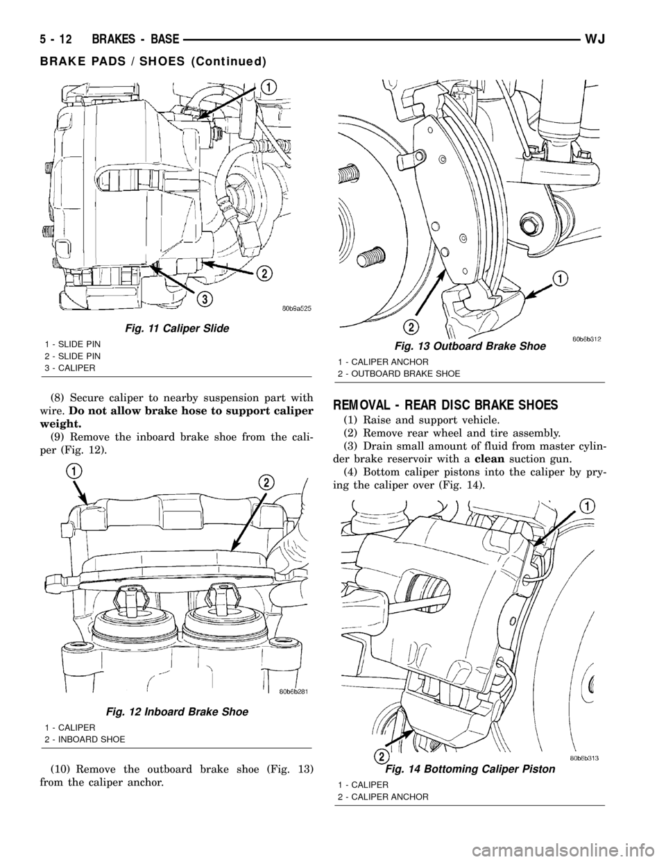
(8) Secure caliper to nearby suspension part with
wire.Do not allow brake hose to support caliper
weight.
(9) Remove the inboard brake shoe from the cali-
per (Fig. 12).
(10) Remove the outboard brake shoe (Fig. 13)
from the caliper anchor.REMOVAL - REAR DISC BRAKE SHOES
(1) Raise and support vehicle.
(2) Remove rear wheel and tire assembly.
(3) Drain small amount of fluid from master cylin-
der brake reservoir with acleansuction gun.
(4) Bottom caliper pistons into the caliper by pry-
ing the caliper over (Fig. 14).
Fig. 11 Caliper Slide
1 - SLIDE PIN
2 - SLIDE PIN
3 - CALIPER
Fig. 12 Inboard Brake Shoe
1 - CALIPER
2 - INBOARD SHOE
Fig. 13 Outboard Brake Shoe
1 - CALIPER ANCHOR
2 - OUTBOARD BRAKE SHOE
Fig. 14 Bottoming Caliper Piston
1 - CALIPER
2 - CALIPER ANCHOR
5 - 12 BRAKES - BASEWJ
BRAKE PADS / SHOES (Continued)