2003 JEEP GRAND CHEROKEE Vale cover
[x] Cancel search: Vale coverPage 89 of 2199

(11) Apply a bead 6.35mm (1/4 inch) of red Mopar
Silicone Rubber Sealant or equivalent to the housing
cover (Fig. 48).
CAUTION: If cover is not installed within 3 to 5 min-
utes, the cover must be cleaned and new RTV
applied or adhesion quality will be compromised.
(12) Install differential cover and tighten cover
bolts in a criss-cross pattern to 41 N´m (30 ft. lbs.).
(13) Fill differential with gear lubricant to bottom
of the fill plug hole.
(14) Tighten fill plug to 34 N´m (25 ft. lbs.).
(15) Remove support and lower the vehicle.
DIFFERENTIAL CASE
BEARINGS
REMOVAL
(1) Remove differential case from housing.
(2) Remove bearings from the differential case
with Puller C-293-PA, Adapters 8352 and Plug
SP-3289 (Fig. 49).
INSTALLATION
NOTE: If replacement differential side bearings or
differential case are being installed, differential side
bearing shim requirements may change. Refer to
Adjustments (Differential Bearing Preload and Gear
Backlash) to determine the proper shim selection.
CAUTION: Vari-lokTplenum must be fully seated
against the differential case prior to installing the
ring gear side differential bearing.
(1) Install differential side bearings with Handle
C-4171 and Installer C-3726-A (Fig. 50).
(2) Install differential in housing.
Fig. 48 DIFFERENTIAL COVER
1 - COVER
2 - SEALANT
3 - SEALANT BEADFig. 49 DIFFERENTIAL CASE BEARING
1 - ADAPTERS
2 - BEARING
3 - DIFFERENTIAL
4 - PLUG
5 - PULLER
3 - 44 FRONT AXLE - 186FBIWJ
DIFFERENTIAL (Continued)
Page 123 of 2199

(11) Apply a 6.35mm (1/4 in.) bead of red Mopar
Silicone Rubber Sealant or equivalent to the housing
cover (Fig. 55).
CAUTION: If cover is not installed within 3 to 5 min-
utes, the cover must be cleaned and new RTV
applied or adhesion quality will be compromised.
Fig. 52 SPREADER LOCATION
1 - DIFFERENTIAL HOUSING
2 - DOWEL
3 - SAFETY HOLD DOWN
4 - SPREADER
5 - TURNBUCKLE
Fig. 53 VARI-LOK
1 - ANTI-ROTATION TAB
2 - OIL FEED TUBE
Fig. 54 BEARING CAP REFERENCE
1 - REFERENCE LETTERS
2 - REFERENCE LETTERS
Fig. 55 DIFFERENTIAL COVER - TYPICAL
1 - COVER
2 - SEALANT
3 - SEALANT BEAD
3 - 78 REAR AXLE - 198RBIWJ
DIFFERENTIAL (Continued)
Page 124 of 2199

(12) Install cover and tighten bolts in a criss-cross
pattern to 41 N´m (30 ft. lbs.).
(13) Refill the differential with Mopar Hypoid
Gear Lubricant or equivalent to bottom of the fill
plug hole.
(14) Install fill hole plug.
(15) Remove support and lower the vehicle.
DIFFERENTIAL-TRAC-LOC
DIAGNOSIS AND TESTING
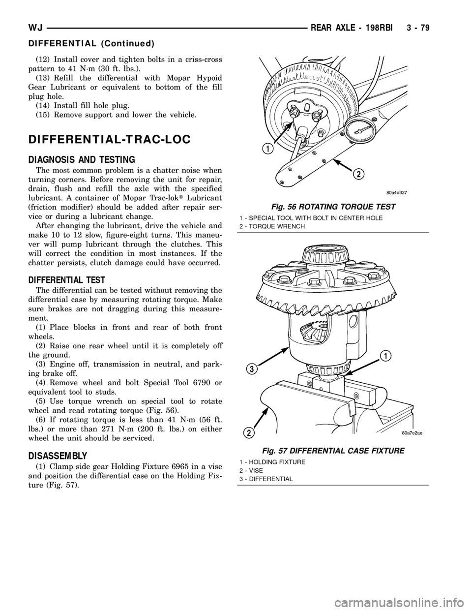
The most common problem is a chatter noise when
turning corners. Before removing the unit for repair,
drain, flush and refill the axle with the specified
lubricant. A container of Mopar Trac-loktLubricant
(friction modifier) should be added after repair ser-
vice or during a lubricant change.
After changing the lubricant, drive the vehicle and
make 10 to 12 slow, figure-eight turns. This maneu-
ver will pump lubricant through the clutches. This
will correct the condition in most instances. If the
chatter persists, clutch damage could have occurred.
DIFFERENTIAL TEST
The differential can be tested without removing the
differential case by measuring rotating torque. Make
sure brakes are not dragging during this measure-
ment.
(1) Place blocks in front and rear of both front
wheels.
(2) Raise one rear wheel until it is completely off
the ground.
(3) Engine off, transmission in neutral, and park-
ing brake off.
(4) Remove wheel and bolt Special Tool 6790 or
equivalent tool to studs.
(5) Use torque wrench on special tool to rotate
wheel and read rotating torque (Fig. 56).
(6) If rotating torque is less than 41 N´m (56 ft.
lbs.) or more than 271 N´m (200 ft. lbs.) on either
wheel the unit should be serviced.
DISASSEMBLY
(1) Clamp side gear Holding Fixture 6965 in a vise
and position the differential case on the Holding Fix-
ture (Fig. 57).
Fig. 56 ROTATING TORQUE TEST
1 - SPECIAL TOOL WITH BOLT IN CENTER HOLE
2 - TORQUE WRENCH
Fig. 57 DIFFERENTIAL CASE FIXTURE
1 - HOLDING FIXTURE
2 - VISE
3 - DIFFERENTIAL
WJREAR AXLE - 198RBI 3 - 79
DIFFERENTIAL (Continued)
Page 163 of 2199

(11) Apply a 6.35mm (1/4 in.) bead of red Mopar
Silicone Rubber Sealant or equivalent to the housing
cover (Fig. 55).
CAUTION: If cover is not installed within 3 to 5 min-
utes, the cover must be cleaned and new RTV
applied or adhesion quality will be compromised.
Fig. 52 SPREADER LOCATION
1 - DIFFERENTIAL HOUSING
2 - DOWEL
3 - SAFETY HOLD DOWN
4 - SPREADER
5 - TURNBUCKLE
Fig. 53 VARI-LOK
1 - ANTI-ROTATION TAB
2 - OIL FEED TUBE
Fig. 54 BEARING CAP REFERENCE
1 - REFERENCE LETTERS
2 - REFERENCE LETTERS
Fig. 55 DIFFERENTIAL COVER - TYPICAL
1 - COVER
2 - SEALANT
3 - SEALANT BEAD
3 - 118 REAR AXLE - 226RBAWJ
DIFFERENTIAL (Continued)
Page 164 of 2199

(12) Install cover and tighten bolts in a criss-cross
pattern to 41 N´m (30 ft. lbs.).
(13) Refill the differential with Mopar Hypoid
Gear Lubricant or equivalent to bottom of the fill
plug hole.
(14) Install fill hole plug.
(15) Remove support and lower the vehicle.
DIFFERENTIAL - TRAC-LOK
DIAGNOSIS AND TESTING
The most common problem is a chatter noise when
turning corners. Before removing the unit for repair,
drain, flush and refill the axle with the specified
lubricant. A container of Mopar Trac-loktLubricant
(friction modifier) should be added after repair ser-
vice or during a lubricant change.
After changing the lubricant, drive the vehicle and
make 10 to 12 slow, figure-eight turns. This maneu-
ver will pump lubricant through the clutches. This
will correct the condition in most instances. If the
chatter persists, clutch damage could have occurred.
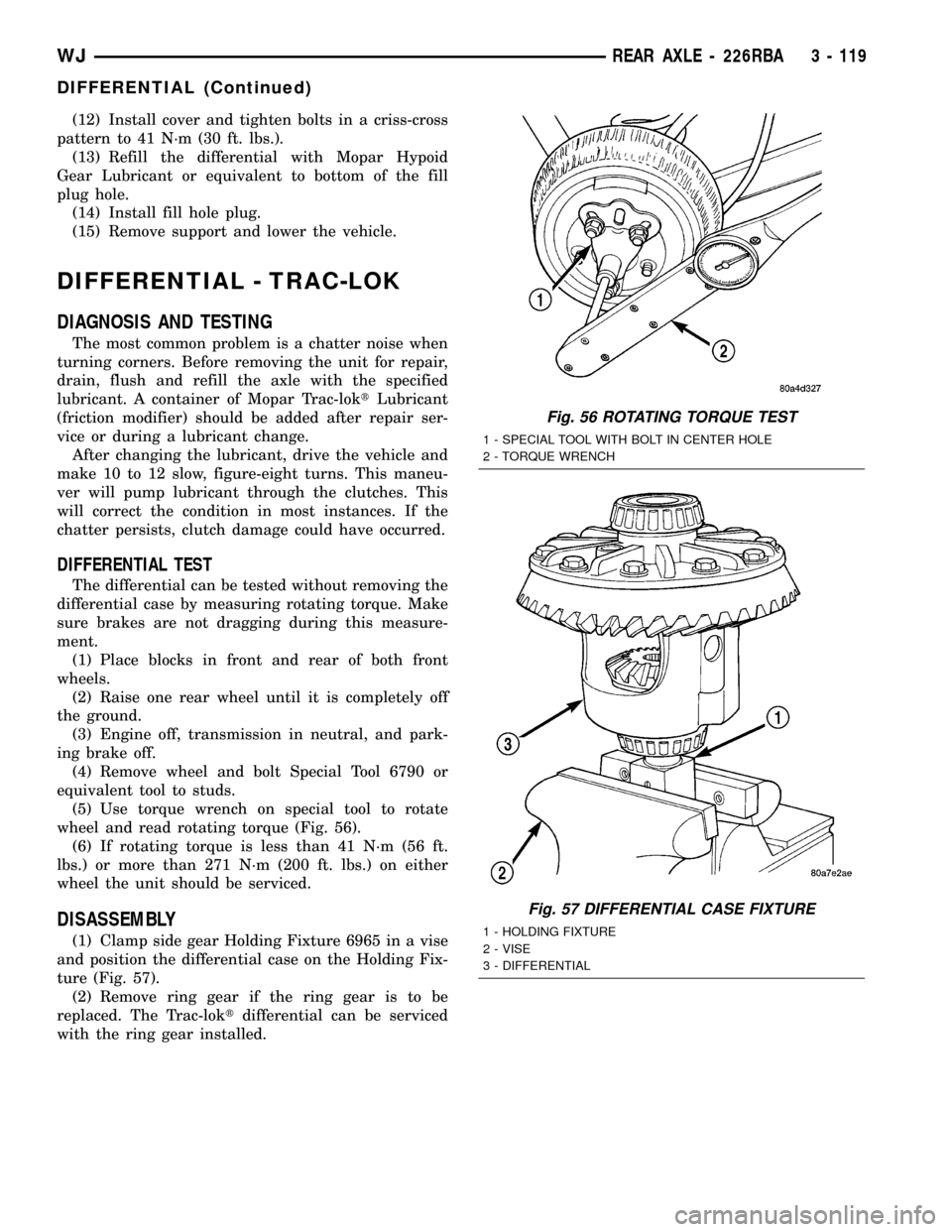
DIFFERENTIAL TEST
The differential can be tested without removing the
differential case by measuring rotating torque. Make
sure brakes are not dragging during this measure-
ment.
(1) Place blocks in front and rear of both front
wheels.
(2) Raise one rear wheel until it is completely off
the ground.
(3) Engine off, transmission in neutral, and park-
ing brake off.
(4) Remove wheel and bolt Special Tool 6790 or
equivalent tool to studs.
(5) Use torque wrench on special tool to rotate
wheel and read rotating torque (Fig. 56).
(6) If rotating torque is less than 41 N´m (56 ft.
lbs.) or more than 271 N´m (200 ft. lbs.) on either
wheel the unit should be serviced.
DISASSEMBLY
(1) Clamp side gear Holding Fixture 6965 in a vise
and position the differential case on the Holding Fix-
ture (Fig. 57).
(2) Remove ring gear if the ring gear is to be
replaced. The Trac-loktdifferential can be serviced
with the ring gear installed.
Fig. 56 ROTATING TORQUE TEST
1 - SPECIAL TOOL WITH BOLT IN CENTER HOLE
2 - TORQUE WRENCH
Fig. 57 DIFFERENTIAL CASE FIXTURE
1 - HOLDING FIXTURE
2 - VISE
3 - DIFFERENTIAL
WJREAR AXLE - 226RBA 3 - 119
DIFFERENTIAL (Continued)
Page 295 of 2199

(7) Reach under the passenger side of the instru-
ment panel near the right cowl side inner panel to
reconnect the antenna coaxial cable connector halves.
(8) Install the trim panel onto the right inner cowl
side. (Refer to 23 - BODY/INTERIOR/COWL TRIM -
INSTALLATION) for the procedures.
(9) Install the scuff plate onto the right front door
sill. (Refer to 23 - BODY/INTERIOR/DOOR SILL
SCUFF PLATE - INSTALLATION) for the proce-
dures.
(10) Reconnect the battery negative cable.
QUARTER GLASS INTEGRAL
ANTENNA - EXPORT
DESCRIPTION
The integral radio antenna element is bonded to
the right rear quarter glass and is replaced with the
glass assembly only.
OPERATION
The integral antenna receives RF (Radio Frequen-
cies) and sends them to the antenna module for
amplification.
DIAGNOSIS AND TESTING - QUARTER GLASS
INTEGRAL ANTENNA - EXPORT
For complete circuit diagrams, refer to the Appro-
priate Wiring Information. To detect breaks in the
integral antenna elements, the following procedure is
required:
(1) Disconnect the antenna module connector from
the antenna.
(2) Using a Ohmmeter, place both leads onto the
connector pins on the integral antenna. If continuity
is present antenna grid is Okay. If continuity is not
present move one lead through the grid in progres-
sion until continuity is detected. A break in the
antenna grid can be repaired using a Mopar Rear
Window Defogger Repair Kit (Part Number 4267922)
or equivalent. (Refer to 8 - ELECTRICAL/WINDOW
DEFOGGER/REAR WINDOW DEFOGGER GRID -
STANDARD PROCEDURE)
RADIO
DESCRIPTION
Available factory-installed radio receivers for this
model include an AM/FM/cassette with CD changer
control feature (RBB sales code), an AM/FM/CD/2-
band graphic equalizer with CD changer control fea-
ture (RBK sales code), or an AM/FM/CD/cassette/2-
band graphic equalizer (RBP sales code). All factory-
installed radio receivers can communicate on theProgrammable Communications Interface (PCI) data
bus network through a separate wire harness connec-
tor. All factory-installed receivers are stereo Electron-
ically Tuned Radios (ETR) and include an electronic
digital clock function.
These radio receivers can only be serviced by an
authorized radio repair station. See the latest War-
ranty Policies and Procedures manual for a current
listing of authorized radio repair stations.
All vehicles are equipped with an Ignition-Off
Draw (IOD) fuse that is removed when the vehicle is
shipped from the factory. This fuse feeds various
accessories that require battery current when the
ignition switch is in the Off position, including the
clock. The IOD fuse is removed to prevent battery
discharge during vehicle storage.
When removing or installing the IOD fuse, it is
important that the ignition switch be in the Off posi-
tion. Failure to place the ignition switch in the Off
position can cause the radio display to become scram-
bled when the IOD fuse is removed and replaced.
Removing and replacing the IOD fuse again, with the
ignition switch in the Off position, will correct the
scrambled display condition.
The IOD fuse should be checked if the radio or
clock displays are inoperative. The IOD fuse is
located in the Power Distribution Center (PDC).
Refer to the fuse layout label on the underside of the
PDC cover for IOD fuse identification and location.
OPERATION
The radio receiver operates on ignition switched
battery current that is available only when the igni-
tion switch is in the On or Accessory positions. The
electronic digital clock function of the radio operates
on fused battery current supplied through the IOD
fuse, regardless of the ignition switch position.
For more information on the features, setting pro-
cedures, and control functions for each of the avail-
able factory-installed radio receivers, refer to the
owner's manual. For complete circuit diagrams, refer
to the appropriate wiring information. The wiring
information includes wiring diagrams, proper wire
and connector repair procedures, details of wire har-
ness routing and retention, connector pin-out infor-
mation and location views for the various wire
harness connectors, splices and grounds.
DIAGNOSIS AND TESTING - RADIO
Any diagnosis of the Audio system should
begin with the use of the DRB IIItdiagnostic
tool. For information on the use of the DRB
IIIt, refer to the appropriate Diagnostic Service
Manual.
If the vehicle is equipped with the optional remote
radio switches located on the steering wheel and the
8A - 16 AUDIOWJ
INSTRUMENT PANEL ANTENNA CABLE (Continued)
Page 1264 of 2199

CLEANING
Thoroughly clean the engine cylinder head and cyl-
inder block mating surfaces. Clean the intake and
engine exhaust manifold and engine cylinder head
mating surfaces. Remove all gasket material and car-
bon.
Check to ensure that no coolant or foreign material
has fallen into the tappet bore area.
Remove the carbon deposits from the combustion
chambers and top of the pistons.
INSPECTION
Use a straightedge and feeler gauge to check the
flatness of the engine cylinder head and block mating
surfaces.
INSTALLATION
NOTE: This procedure can be done with the engine
in or out of the vehicle.
The engine cylinder head gasket is a composition
gasket. The gasket is to be installed DRY.DO NOT
use a gasket sealing compound on the gasket.
If the engine cylinder head is to be replaced and
the original valves used, measure the valve stem
diameter. Only standard size valves can be used with
a service replacement engine cylinder head unless
the replacement head valve stem guide bores are
reamed to accommodate oversize valve stems.
Remove all carbon buildup and reface the valves.
(1) Remove the shop towels from the cylinder
bores. Coat the bores with clean engine oil.
(2) Position the engine cylinder head gasket (with
the numbers facing up) using the alignment dowels
in the cylinder block, to position the gasket.
CAUTION: Engine cylinder head bolts should be
reused only once. Replace the head bolts if they
were used before or if they have a paint dab on the
top of the bolt.
(3) With bolt No.14 held in place (tape around
bolt), install the engine cylinder head over the same
dowels used to locate the gasket. Remove the tape
from bolt No.14.
(4) Coat the threads of stud bolt No.11 with Loc-
tite 592 sealant, or equivalent.
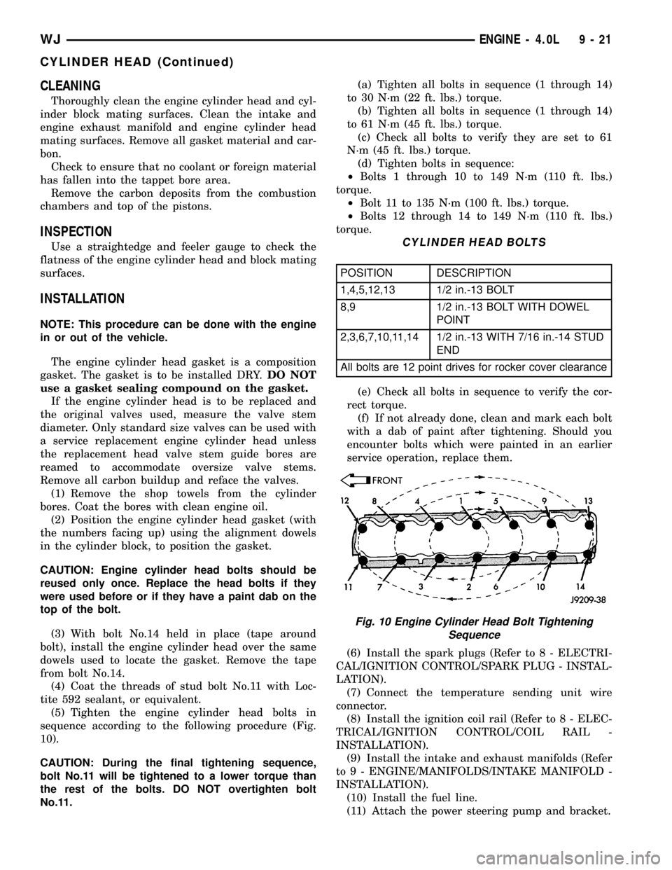
(5) Tighten the engine cylinder head bolts in
sequence according to the following procedure (Fig.
10).
CAUTION: During the final tightening sequence,
bolt No.11 will be tightened to a lower torque than
the rest of the bolts. DO NOT overtighten bolt
No.11.(a) Tighten all bolts in sequence (1 through 14)
to 30 N´m (22 ft. lbs.) torque.
(b) Tighten all bolts in sequence (1 through 14)
to 61 N´m (45 ft. lbs.) torque.
(c) Check all bolts to verify they are set to 61
N´m (45 ft. lbs.) torque.
(d) Tighten bolts in sequence:
²Bolts 1 through 10 to 149 N´m (110 ft. lbs.)
torque.
²Bolt 11 to 135 N´m (100 ft. lbs.) torque.
²Bolts 12 through 14 to 149 N´m (110 ft. lbs.)
torque.
CYLINDER HEAD BOLTS
POSITION DESCRIPTION
1,4,5,12,13 1/2 in.-13 BOLT
8,9 1/2 in.-13 BOLT WITH DOWEL
POINT
2,3,6,7,10,11,14 1/2 in.-13 WITH 7/16 in.-14 STUD
END
All bolts are 12 point drives for rocker cover clearance
(e) Check all bolts in sequence to verify the cor-
rect torque.
(f) If not already done, clean and mark each bolt
with a dab of paint after tightening. Should you
encounter bolts which were painted in an earlier
service operation, replace them.
(6) Install the spark plugs (Refer to 8 - ELECTRI-
CAL/IGNITION CONTROL/SPARK PLUG - INSTAL-
LATION).
(7) Connect the temperature sending unit wire
connector.
(8) Install the ignition coil rail (Refer to 8 - ELEC-
TRICAL/IGNITION CONTROL/COIL RAIL -
INSTALLATION).
(9) Install the intake and exhaust manifolds (Refer
to 9 - ENGINE/MANIFOLDS/INTAKE MANIFOLD -
INSTALLATION).
(10) Install the fuel line.
(11) Attach the power steering pump and bracket.
Fig. 10 Engine Cylinder Head Bolt Tightening
Sequence
WJENGINE - 4.0L 9 - 21
CYLINDER HEAD (Continued)
Page 1270 of 2199

INSPECTION
Inspect the pivot surface area of each rocker arm.
Replace any that are scuffed, pitted, cracked or
excessively worn.
Inspect the valve stem tip contact surface of each
rocker arm and replace any rocker arm that is deeply
pitted.
Inspect each push rod end for excessive wear and
replace as required. If any push rod is excessively
worn because of lack of oil, replace it and inspect the
corresponding hydraulic tappet for excessive wear.
Inspect the push rods for straightness by rolling
them on a flat surface or by shining a light between
the push rod and the flat surface.
A wear pattern along the length of the push rod is
not normal. Inspect the engine cylinder head for
obstruction if this condition exists.
INSTALLATION
NOTE: This procedure can be done with the engine
in or out of the vehicle.
(1) Lubricate the ball ends of the push rods with
MopartEngine Oil Supplement, or equivalent and
install push rods in their original locations. Ensurethat the bottom end of each push rod is centered in
the tappet plunger cap seat.
(2) Using MopartEngine Oil Supplement, or
equivalent, lubricate the area of the rocker arm that
the pivot contacts. Install rocker arms, pivots and
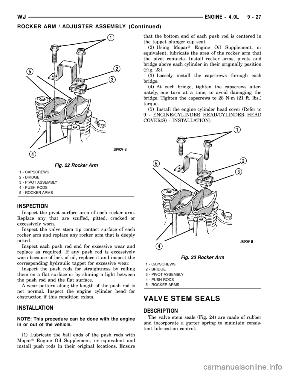
bridge above each cylinder in their originally position
(Fig. 23).
(3) Loosely install the capscrews through each
bridge.
(4) At each bridge, tighten the capscrews alter-
nately, one turn at a time, to avoid damaging the
bridge. Tighten the capscrews to 28 N´m (21 ft. lbs.)
torque.
(5) Install the engine cylinder head cover (Refer to
9 - ENGINE/CYLINDER HEAD/CYLINDER HEAD
COVER(S) - INSTALLATION).
VALVE STEM SEALS
DESCRIPTION
The valve stem seals (Fig. 24) are made of rubber
and incorporate a garter spring to maintain consis-
tent lubrication control.
Fig. 22 Rocker Arm
1 - CAPSCREWS
2 - BRIDGE
3 - PIVOT ASSEMBLY
4 - PUSH RODS
5 - ROCKER ARMS
Fig. 23 Rocker Arm
1 - CAPSCREWS
2 - BRIDGE
3 - PIVOT ASSEMBLY
4 - PUSH RODS
5 - ROCKER ARMS
WJENGINE - 4.0L 9 - 27
ROCKER ARM / ADJUSTER ASSEMBLY (Continued)