2003 INFINITI G35 manual transmission
[x] Cancel search: manual transmissionPage 12 of 256
O To return the seat to its original position,
raise the seatback and lock the seat. The
seat will return to its original position.
O The front passenger seat will stop at 7 in
(175 mm) from its frontmost position to
retain space for the rear passenger.
CAUTIONO When returning the seat to its original
position, confirm the seat and seat-
back are locked properly.
O Be careful not to pinch your hand or
foot or bump your head when operat-
ing the walk-in seat. The seatback will
fold down rapidly.
O Do not put any objects in front or rear
of the seat. They may be pinched and
damaged.
The automatic forwarding and reversing will
not work or stop under the following condi-
tions:
O When the vehicle speed is above 4 MPH (7
km/h).
O When the seat belt is fastened. O When the selector lever is not in the P
(Park) position (Automatic transmission
model's driver's seat) or the parking brake
is not applied (Manual transmission mod-
el's driver's seat)
O When the door is closed.
O When the slide adjusting switch is oper-
ated.
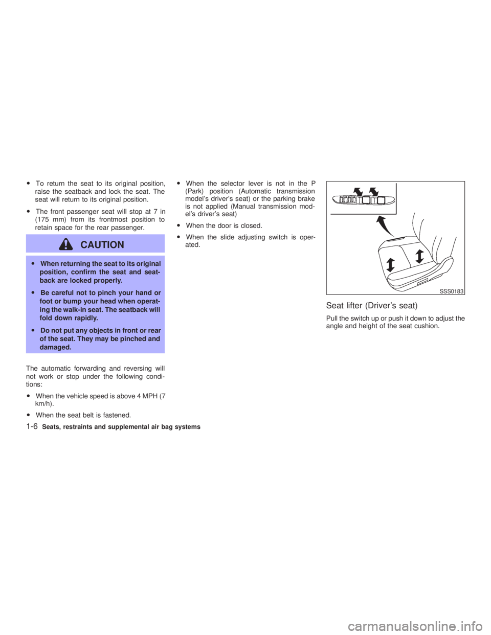
Seat lifter (Driver's seat) Pull the switch up or push it down to adjust the
angle and height of the seat cushion. SSS0183
1-6 Seats, restraints and supplemental air bag systems
Z 02.7.29/V35-D/V5.0
X
Page 54 of 256

2 Instruments and controls Instrument panel ....................................................... 2-2
Meters and gauges ................................................... 2-3
Speedometer and odometer ................................ 2-4
Tachometer .......................................................... 2-4
Engine coolant temperature gauge ...................... 2-5
Fuel gauge ........................................................... 2-5
Compass display ...................................................... 2-6
Warning/indicator lights and audible reminders ........ 2-9
Checking bulbs ..................................................... 2-9
Warning lights....................................................... 2-9
Indicator lights .................................................... 2-11
Audible reminders .............................................. 2-13
Security systems ..................................................... 2-13
Vehicle security system ...................................... 2-13
Infiniti Vehicle Immobilizer System ................... 2-14
Windshield wiper and washer switch ...................... 2-16
Rear window and outside mirror (if so equipped)
defroster switch ....................................................... 2-16
Headlight and turn signal switch ............................. 2-17
Xenon headlights (if so equipped) ..................... 2-17
Headlight switch ................................................. 2-17
Turn signal switch .............................................. 2-19
Fog light switch ....................................................... 2-20
Hazard warning flasher switch ................................ 2-20 Horn......................................................................... 2-21
Heated seats (if so equipped) ................................. 2-21
Vehicle dynamics control (VDC) off switch ............ 2-22
Clock ....................................................................... 2-23
Adjusting the time............................................... 2-23
Power outlet ............................................................ 2-23
Cigarette lighter and ashtray (accessory) ............... 2-24
Storage .................................................................... 2-25
Instrument pocket (Except for Navigation system
equipped models) ............................................... 2-25
Pocket (Manual transmission model) ................. 2-25
Glasses case ...................................................... 2-26
Cup holder .......................................................... 2-26
Glove box ........................................................... 2-27
Upper glove box (Except for Navigation system
equipped models) ............................................... 2-28
Console box ....................................................... 2-28
Rear armrest pocket ........................................... 2-29
Cargo net............................................................ 2-29
Coat hook (Coupe) ............................................. 2-30
Stowing golf bags ............................................... 2-30
Windows .................................................................. 2-31
Power windows .................................................. 2-31
Automatic adjusting function (Coupe) ................ 2-33
Z 02.7.29/V35-D/V5.0
X
Page 57 of 256

See the page indicated in parentheses for
operating details.
*: Refer to the separate Navigation System
Owner's Manual.
1. Warning/Indicator lights
2. Speedometer
3. Tachometer
4. Engine coolant temperature gauge
5. Automatic transmission position indicator 6. Odometer (Total/Twin trip)
7. Reset knob for trip odometer
8. Fuel gauge SIC1828METERS AND GAUGES
Instruments and controls
2-3
Z 02.7.29/V35-D/V5.0
X
Page 79 of 256

only. The use of the cigarette lighter
socket as a power source for any other
accessory is not recommended.
INSTRUMENT POCKET (Except for
Navigation system equipped
models)
WARNING The instrument pocket should not be
used while driving so full attention may
be given to vehicle operation. POCKET (Manual transmission
model) SIC1843 SIC2026
STORAGE
Instruments and controls
2-25
Z 02.7.29/V35-D/V5.0
X
Page 113 of 256
AUTOMATIC SEAT POSITIONER
OPERATION This system is designed so that the driver's
seat will automatically move when the auto-
matic transmission selector lever is in the P
(Park) position or when the parking brake is
applied (manual transmission model). This al-
lows the driver to get in and out of the driver's
seat more easily.
When one of the following conditions is met,
the driver's seat will slide backward. (AT mod-
els only)
O When the key is removed from the ignition
switch.
O When the driver's door is opened with the
key turned to ACC or LOCK.
O When the key is turned from ON to ACC
with the driver's door open.
When one of the following conditions is met,
the driver's seat will return to the positions
before being set. (AT models only)
O When the key is inserted into the ignition
switch.
O When the driver's door is closed with the
key turned to LOCK.
O When the key is turned from ACC to ON with the driver's door open.
PROCEDURE FOR STORING
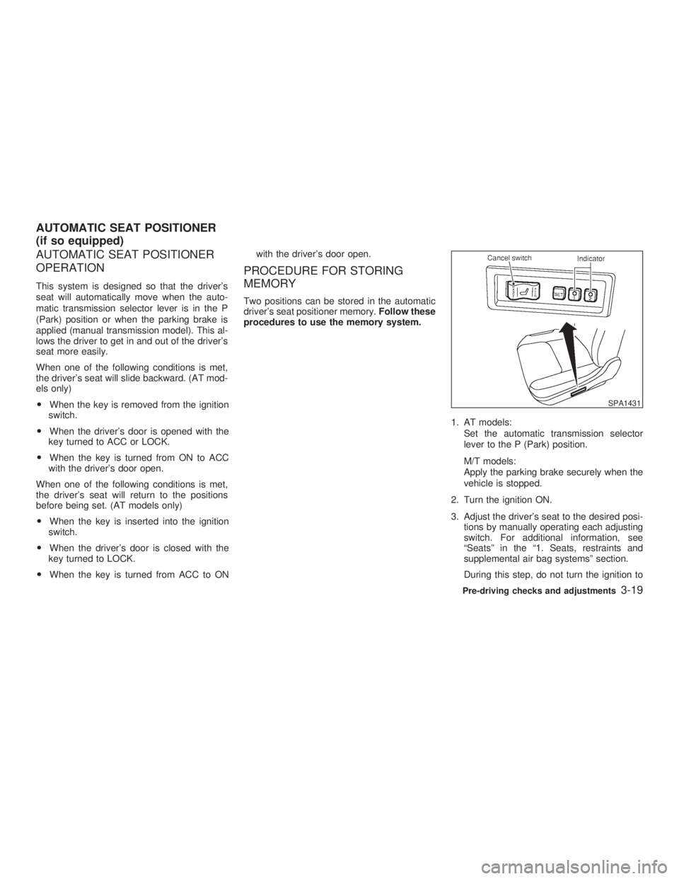
MEMORY Two positions can be stored in the automatic
driver's seat positioner memory. Follow these
procedures to use the memory system.
1. AT models:
Set the automatic transmission selector
lever to the P (Park) position.
M/T models:
Apply the parking brake securely when the
vehicle is stopped.
2. Turn the ignition ON.
3. Adjust the driver's seat to the desired posi-
tions by manually operating each adjusting
switch. For additional information, see
ªSeatsº in the ª1. Seats, restraints and
supplemental air bag systemsº section.
During this step, do not turn the ignition to SPA1431
AUTOMATIC SEAT POSITIONER
(if so equipped)
Pre-driving checks and adjustments
3-19
Z 02.7.29/V35-D/V5.0
X
Page 135 of 256
5 Starting and driving Precautions when starting and driving ...................... 5-2
Exhaust gas (Carbon monoxide).......................... 5-2
Three way catalyst ............................................... 5-3
Avoiding collision and rollover .............................. 5-3
Drinking alcohol/drugs and driving ....................... 5-4
Ignition switch............................................................ 5-4
Automatic transmission ........................................ 5-4
Manual transmission ............................................ 5-5
Key positions ........................................................ 5-6
Infiniti vehicle immobilizer system ....................... 5-6
Before starting the engine ......................................... 5-7
Starting the engine .................................................... 5-7
Driving the vehicle ..................................................... 5-8
Automatic transmission ........................................ 5-8
Manual transmission .......................................... 5-12
Parking brake .......................................................... 5-14
Cruise control .......................................................... 5-15
Precautions on cruise control ............................. 5-15
Cruise control operations ................................... 5-15
Break-in schedule ................................................... 5-17
Increasing fuel economy ......................................... 5-17
Parking/parking on hills ........................................... 5-18
Power steering ........................................................ 5-19
Brake system .......................................................... 5-19 Braking precautions............................................ 5-19
Anti-lock brake system (ABS) ........................... 5-20
Vehicle dynamics control (VDC) system................. 5-21
Cold weather driving ............................................... 5-23
Freeing a frozen door lock ................................. 5-23
Anti-freeze .......................................................... 5-23
Battery ................................................................ 5-23
Draining of coolant water ................................... 5-23
Tire equipment ................................................... 5-23
Special winter equipment ................................... 5-23
Driving on snow or ice ....................................... 5-24
Engine block heater (if so equipped) ................. 5-24
Z 02.7.29/V35-D/V5.0
X
Page 139 of 256
LOCK position, proceed as follows to remove
the key:
1. Move the selector lever into the P (Park)
position.
2. Turn the ignition key slightly in the ON
direction.
3. Turn the key toward the LOCK position.
4. Remove the key.
If the key is removed from the ignition switch,
the selector lever cannot be moved from P
(Park) position. The selector lever can be
moved if the ignition switch is in the ON
position and the foot brake pedal is de-
pressed.
There is an OFF position in between LOCK
and ACC, although it does not show on the
lock cylinder. When the ignition is in OFF the
steering wheel is not locked.
In order for the steering wheel to be locked, it
must be turned about 1/6 of a turn counter-
clockwise from the straight up position.
To lock the steering wheel, turn the key to
the LOCK position. Remove the key. To
unlock the steering wheel, insert the key
and turn it gently while rotating the steer-
ing wheel slightly right and left. WARNING Never remove or turn the key to the
LOCK position while driving. The steer-
ing wheel will lock. This may cause the
driver to lose control of the vehicle and
could result in serious vehicle damage
and/or personal injury.
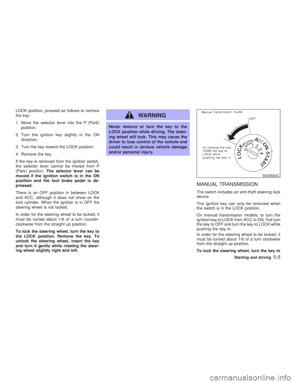
MANUAL TRANSMISSION The switch includes an anti-theft steering lock
device.
The ignition key can only be removed when
the switch is in the LOCK position.
On manual transmission models, to turn the
ignition key to LOCK from ACC or ON, first turn
the key to OFF and turn the key to LOCK while
pushing the key in.
In order for the steering wheel to be locked, it
must be turned about 1/6 of a turn clockwise
from the straight up position.
To lock the steering wheel, turn the key to SSD0082C
Starting and driving
5-5
Z 02.7.29/V35-D/V5.0
X
Page 141 of 256
O Make sure the area around the vehicle is
clear.
O Maintenance items should be checked pe-
riodically, e.g., each time you check engine
oil.
O Check that all windows and lights are clean.
O Visually inspect tires for their appearance
and condition. Also, check tires for proper
inflation.
O Lock all doors.
O Position seat and adjust head restraints.
O Adjust inside and outside mirrors.
O Fasten seat belts and ask all passengers to
do likewise.
O Check the operation of warning lights when
key is turned to the ON (3) position. 1. Apply the parking brake.
2. Automatic transmission:
Move the selector lever to P (Park) or N
(Neutral). (P preferred.)
The starter is designed not to operate if the
selector lever is in one of the driving posi-
tions.
Manual transmission:
Move the shift lever to N (Neutral) position,
and depress the clutch pedal to the floor
while cranking the engine.
The starter is designed not to operate un-
less the clutch pedal is fully depressed.
3. Crank the engine with your foot off the
accelerator pedal by turning the ignition
key to START. Release the key when the
engine starts. If the engine starts, but fails
to run, repeat the above procedure.
O If the engine is very hard to start in ex-
tremely cold weather or when restarting,
depress the accelerator pedal a little (ap-
proximately 1/5 to the floor) and hold it then
crank the engine. Release the key and the
accelerator pedal when the engine starts.
O If the engine is very hard to start because it
is flooded, depress the accelerator pedal all the way to the floor and hold it. Crank the
engine for 5 to 6 seconds. After cranking
the engine, release the accelerator pedal.
Crank the engine with your foot off the
accelerator pedal by turning the ignition
key to START. Release the key when the
engine starts. If the engine starts, but fails
to run, repeat the above procedure.
CAUTION Do not operate the starter for more than
15 seconds at a time. If the engine does
not start, turn the key off and wait 10
seconds before cranking again, other-
wise the starter could be damaged.
4. Warm-up
Allow the engine to idle for at least 30
seconds after starting. Drive at moderate
speed for a short distance first, especially in
cold weather.BEFORE STARTING THE ENGINE STARTING THE ENGINE
Starting and driving
5-7
Z 02.7.29/V35-D/V5.0
X