2003 INFINITI G35 clock
[x] Cancel search: clockPage 54 of 256

2 Instruments and controls Instrument panel ....................................................... 2-2
Meters and gauges ................................................... 2-3
Speedometer and odometer ................................ 2-4
Tachometer .......................................................... 2-4
Engine coolant temperature gauge ...................... 2-5
Fuel gauge ........................................................... 2-5
Compass display ...................................................... 2-6
Warning/indicator lights and audible reminders ........ 2-9
Checking bulbs ..................................................... 2-9
Warning lights....................................................... 2-9
Indicator lights .................................................... 2-11
Audible reminders .............................................. 2-13
Security systems ..................................................... 2-13
Vehicle security system ...................................... 2-13
Infiniti Vehicle Immobilizer System ................... 2-14
Windshield wiper and washer switch ...................... 2-16
Rear window and outside mirror (if so equipped)
defroster switch ....................................................... 2-16
Headlight and turn signal switch ............................. 2-17
Xenon headlights (if so equipped) ..................... 2-17
Headlight switch ................................................. 2-17
Turn signal switch .............................................. 2-19
Fog light switch ....................................................... 2-20
Hazard warning flasher switch ................................ 2-20 Horn......................................................................... 2-21
Heated seats (if so equipped) ................................. 2-21
Vehicle dynamics control (VDC) off switch ............ 2-22
Clock ....................................................................... 2-23
Adjusting the time............................................... 2-23
Power outlet ............................................................ 2-23
Cigarette lighter and ashtray (accessory) ............... 2-24
Storage .................................................................... 2-25
Instrument pocket (Except for Navigation system
equipped models) ............................................... 2-25
Pocket (Manual transmission model) ................. 2-25
Glasses case ...................................................... 2-26
Cup holder .......................................................... 2-26
Glove box ........................................................... 2-27
Upper glove box (Except for Navigation system
equipped models) ............................................... 2-28
Console box ....................................................... 2-28
Rear armrest pocket ........................................... 2-29
Cargo net............................................................ 2-29
Coat hook (Coupe) ............................................. 2-30
Stowing golf bags ............................................... 2-30
Windows .................................................................. 2-31
Power windows .................................................. 2-31
Automatic adjusting function (Coupe) ................ 2-33
Z 02.7.29/V35-D/V5.0
X
Page 56 of 256

1. Headlight, fog light and turn signal switch
(P.2-17)
2. Steering switch for audio control (P.4-16)
3. Driver supplemental air bag (P.1-8)/Horn
(P.2-21)
4. Meters/gauges (P.2-3) 5. Cruise control main/set switch (P.5-11)
6. Windshield wiper/washer switch (P.2-16)
7. Center ventilator (P.4-2)
8. Center display - Compass (P.2-6), Air con-
ditioner (P.2-6), Ambient temperature
(P.2-6) 9. Rear window and outside mirror (if so
equipped) defogger switch (P.2-16)
10. Heater/air conditioner control (P.4-3)
11. Clock (P.2-23)
12. Navigation system* (if so equipped)
13. Security indicator light (P.2-14)
14. Passenger supplemental air bag (P.1-8)
15. Upper glove box (Except for Navigation
system equipped models) (P.2-26)
16. Side window defroster
17. Side ventilator (P.4-2)
18. Hood lock release handle (P.3-9)
19. Instrument brightness control switch
(P.2-19)
20. Trunk lid release switch (P.3-11)
21. VDC (Vehicle Dynamics Control) OFF
switch (P.2-22)
22. Outside mirror remote control (P.3-15)
23. Fuse box (P.8-20)
24. Tilting steering wheel lock lever (P.3-14)
25. Ignition switch/steering lock (P.5-4)
26. Cigarette lighter (P.2-24)
27. Ashtray (P.2-24)/Pocket
28. Radio/cassette player (P.4-8)/CD player
(P.4-8)
29. Hazard warning flasher switch (P.2-20)
30. Heated seat switch (P.2-21)
31. Power outlet
32. Glove box (P.2-26) SIC2023INSTRUMENT PANEL
2-2 Instruments and controls
Z 02.7.29/V35-D/V5.0
X
Page 73 of 256

Instrument brightness control The instrument brightness control operates
when the light switch is in the or
position.
Turn the control to adjust the brightness of
instrument panel lights and clock (except
power window switch lights).
When the control is turned upward until it
stops, the light intensity will be at maximum.
When the control is turned downward until it
stops, the light will be turned off. Headlight beam select To select the high beam, push the lever for-
ward. Pull it back to select the low beam.
Flashing signal Pulling the lever toward you will flash the
headlight high beam.
Daytime running light system
(Canada only) The headlights automatically illuminate at a
reduced intensity when the engine is started
with the parking brake released. The daytime
running lights operate with the headlight switch
in the OFF position or in the position.
Turn the headlight switch to the position
for full illumination when driving at night.
If the parking brake is applied before the
engine is started, the daytime running lights do
not illuminate. The daytime running lights illu-
minate once the parking brake is released.
The daytime running lights will remain on until
the ignition switch is turned off. WARNING When the daytime running light system
is active, tail lights on your vehicle are
not on. It is necessary at dusk to turn on
your headlights. Failure to do so could
cause an accident injuring yourself and
others.
TURN SIGNAL SWITCH
Turn signal Move the lever up or down to signal the turning
direction. When the turn is completed, the turn
signals cancel automatically.
Lane change signal To indicate a lane change, move the lever up
or down to the point where lights begin flash-
ing.SIC0922
Instruments and controls
2-19
Z 02.7.29/V35-D/V5.0
X
Page 77 of 256
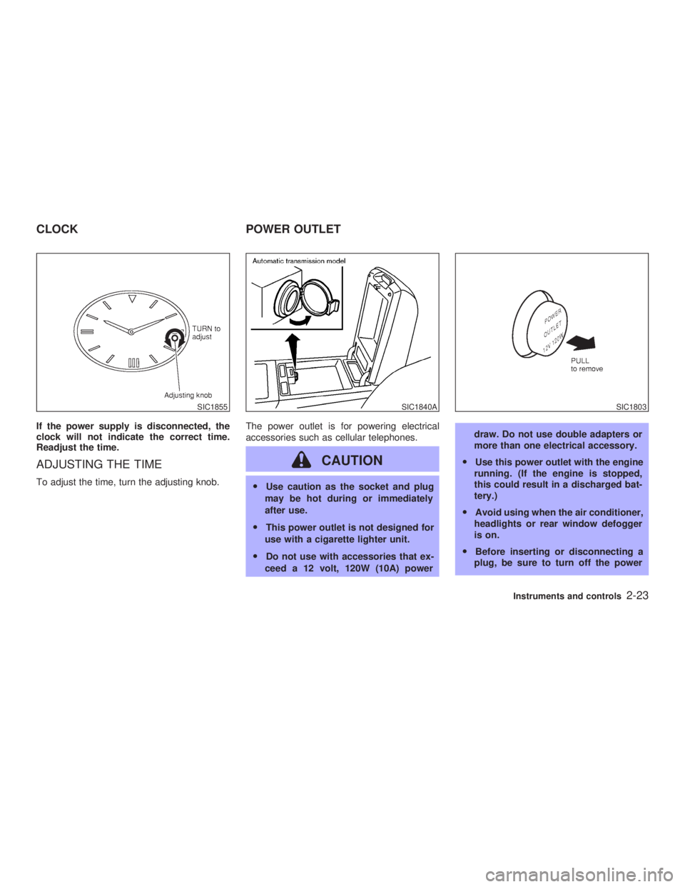
If the power supply is disconnected, the
clock will not indicate the correct time.
Readjust the time.
ADJUSTING THE TIME To adjust the time, turn the adjusting knob. The power outlet is for powering electrical
accessories such as cellular telephones.
CAUTION O Use caution as the socket and plug
may be hot during or immediately
after use.
O This power outlet is not designed for
use with a cigarette lighter unit.
O Do not use with accessories that ex-
ceed a 12 volt, 120W (10A) power draw. Do not use double adapters or
more than one electrical accessory.
O Use this power outlet with the engine
running. (If the engine is stopped,
this could result in a discharged bat-
tery.)
O Avoid using when the air conditioner,
headlights or rear window defogger
is on.
O Before inserting or disconnecting a
plug, be sure to turn off the powerSIC1855 SIC1840A SIC1803
CLOCK POWER OUTLET
Instruments and controls
2-23
Z 02.7.29/V35-D/V5.0
X
Page 105 of 256
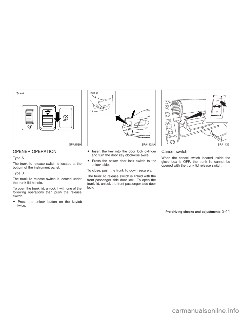
OPENER OPERATION Type A
The trunk lid release switch is located at the
bottom of the instrument panel.
Type B
The trunk lid release switch is located under
the trunk lid handle.
To open the trunk lid, unlock it with one of the
following operations then push the release
switch.
O Press the unlock button on the keyfob
twice. O Insert the key into the door lock cylinder
and turn the door key clockwise twice.
O Press the power door lock switch to the
unlock side.
To close, push the trunk lid down securely.
The trunk lid release switch is linked with the
front passenger side door lock. To open the
trunk lid, unlock the front passenger side door
lock. Cancel switch When the cancel switch located inside the
glove box is OFF, the trunk lid cannot be
opened with the trunk lid release switch.SPA1589 SPA1424A SPA1432
Pre-driving checks and adjustments
3-11
Z 02.7.29/V35-D/V5.0
X
Page 108 of 256
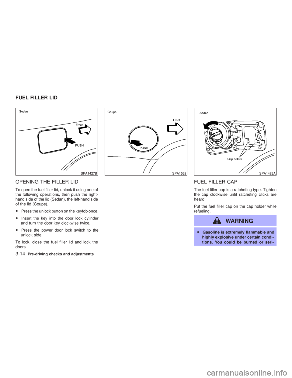
OPENING THE FILLER LID To open the fuel filler lid, unlock it using one of
the following operations, then push the right-
hand side of the lid (Sedan), the left-hand side
of the lid (Coupe).
O Press the unlock button on the keyfob once.
O Insert the key into the door lock cylinder
and turn the door key clockwise twice.
O Press the power door lock switch to the
unlock side.
To lock, close the fuel filler lid and lock the
doors. FUEL FILLER CAP The fuel filler cap is a ratcheting type. Tighten
the cap clockwise until ratcheting clicks are
heard.
Put the fuel filler cap on the cap holder while
refueling.
WARNING O Gasoline is extremely flammable and
highly explosive under certain condi-
tions. You could be burned or seri-SPA1427B SPA1562 SPA1428A
FUEL FILLER LID
3-14 Pre-driving checks and adjustments
Z 02.7.29/V35-D/V5.0
X
Page 123 of 256
movement, reception conditions will constantly
change. Buildings, terrain, signal distance and
interference from other vehicles can work
against ideal reception. Described below are
some of the factors that can affect your radio
reception.
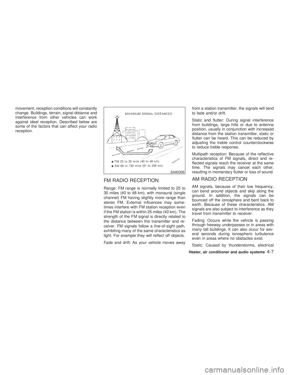
FM RADIO RECEPTION Range: FM range is normally limited to 25 to
30 miles (40 to 48 km), with monaural (single
channel) FM having slightly more range than
stereo FM. External influences may some-
times interfere with FM station reception even
if the FM station is within 25 miles (40 km). The
strength of the FM signal is directly related to
the distance between the transmitter and re-
ceiver. FM signals follow a line-of-sight path,
exhibiting many of the same characteristics as
light. For example they will reflect off objects.
Fade and drift: As your vehicle moves away from a station transmitter, the signals will tend
to fade and/or drift.
Static and flutter: During signal interference
from buildings, large hills or due to antenna
position, usually in conjunction with increased
distance from the station transmitter, static or
flutter can be heard. This can be reduced by
adjusting the treble control counterclockwise
to reduce treble response.
Multipath reception: Because of the reflective
characteristics of FM signals, direct and re-
flected signals reach the receiver at the same
time. The signals may cancel each other,
resulting in momentary flutter or loss of sound.
AM RADIO RECEPTION AM signals, because of their low frequency,
can bend around objects and skip along the
ground. In addition, the signals can be
bounced off the ionosphere and bent back to
earth. Because of these characteristics. AM
signals are also subject to interference as they
travel from transmitter to receiver.
Fading: Occurs while the vehicle is passing
through freeway underpasses or in areas with
many tall buildings. It can also occur for sev-
eral seconds during ionospheric turbulence
even in areas where no obstacles exist.
Static: Caused by thunderstorms, electrical SAA0306
Heater, air conditioner and audio systems
4-7
Z 02.7.29/V35-D/V5.0
X
Page 139 of 256
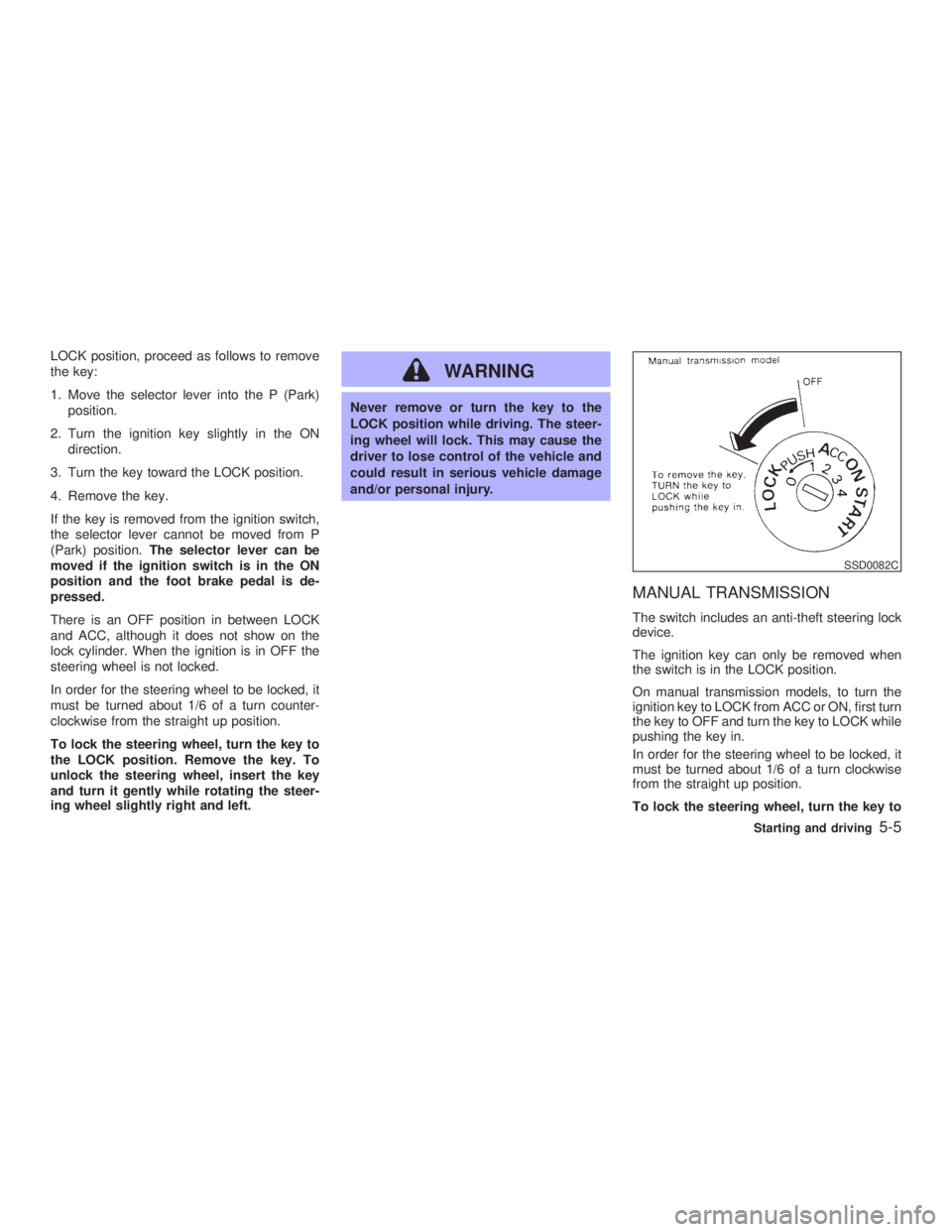
LOCK position, proceed as follows to remove
the key:
1. Move the selector lever into the P (Park)
position.
2. Turn the ignition key slightly in the ON
direction.
3. Turn the key toward the LOCK position.
4. Remove the key.
If the key is removed from the ignition switch,
the selector lever cannot be moved from P
(Park) position. The selector lever can be
moved if the ignition switch is in the ON
position and the foot brake pedal is de-
pressed.
There is an OFF position in between LOCK
and ACC, although it does not show on the
lock cylinder. When the ignition is in OFF the
steering wheel is not locked.
In order for the steering wheel to be locked, it
must be turned about 1/6 of a turn counter-
clockwise from the straight up position.
To lock the steering wheel, turn the key to
the LOCK position. Remove the key. To
unlock the steering wheel, insert the key
and turn it gently while rotating the steer-
ing wheel slightly right and left. WARNING Never remove or turn the key to the
LOCK position while driving. The steer-
ing wheel will lock. This may cause the
driver to lose control of the vehicle and
could result in serious vehicle damage
and/or personal injury.
MANUAL TRANSMISSION The switch includes an anti-theft steering lock
device.
The ignition key can only be removed when
the switch is in the LOCK position.
On manual transmission models, to turn the
ignition key to LOCK from ACC or ON, first turn
the key to OFF and turn the key to LOCK while
pushing the key in.
In order for the steering wheel to be locked, it
must be turned about 1/6 of a turn clockwise
from the straight up position.
To lock the steering wheel, turn the key to SSD0082C
Starting and driving
5-5
Z 02.7.29/V35-D/V5.0
X