Page 245 of 349

CONTROLS AND EQUIPMENT1- 51
The outside rearview mirrors are equipped with
a remote control for your convenience. It is operated by the control lever in the bottom frontcorner of the window. Before driving away, always check that your
mirrors are positioned so you can see directlybehind you. When using the mirror, alwaysexercise caution when attempting to judge thedistance of vehicles behind or along side ofyou. CAUTION:
If the mirror control is jammed with ice, do
not attempt to break it free using the control handle or by manipulating the face of themirror. Use an approved spray de-icer (notradiator antifreeze) to release the frozenmechanism or move the vehicle to a warmplace and allow the ice to melt. B510A01A-AAT OUTSIDE REARVIEW MIRROR Manual Type
B510A01HP.DAG
B510B01Y-EAT Electric Type (Not all models)B510B01HP.DAG
The outside rearview mirrors can be adjusted to your preferred rear vision, both directly behindthe vehicle, and to the rear of the left and rightsides. The remote control outside rearview mirror switch controls the adjustments for both rightand left outside mirrors. To adjust the position of either mirror:
1. Move the selecting switch to the right or left to activate the adjustable mechanism for the corresponding door mirror.
2. Now, adjust mirror angle by depressing the appropriate perimeter switch as illustrated.B500B01HP.DAG
The multi box may be opened by pulling it out
by its grip.It is used for storing small articles. B500B01HP-DAT MULTI BOX (Not all models)
Page 246 of 349

CONTROLS AND EQUIPMENT
1- 52 B510C01HP.DAG
YB270D2-E FOLDING THE OUTSIDE REARVIEW MIRRORS To fold the outside rearview mirrors, push them towards the rear. The outside rearview mirrors can be folded rearward for parking in restricted areas. WARNING: Do not adjust or fold the outside rearviewmirrors whilst the vehicle is moving. Thiscould result in loss of control, and an acci-dent causing death, serious injury or prop-erty damage.
CAUTION:
o Do not operate the switch continuously for an unnecessary length of time.
o Scraping ice from the mirror face could cause permanent damage. To remove anyice, use a sponge, soft cloth or approvedde-icer.
WARNING: Be careful when judging the size or distance
of any object seen in the passenger side rear view mirror. It is a convex mirror with acurved surface. Any objects seen in thismirror are closer than they appear. HPB270C1-E OUTSIDE REARVIEW MIRROR HEATER (Not all models) The outside rearview mirror heater is actuated in connection with heated rear window. So, to heat the outside rearview mirror glass, push in the switch for heated rear window. The rearview mirror glass will be heated for defrosting or defogging and will give you im-proved rear vision in all weather conditions. Push the switch again to turn the heater off. The outside rear view mirror heater automati-cally turns itself off after 20 minutes.
B510D01E
B380A02HP
Type A
Type B
Page 247 of 349

CONTROLS AND EQUIPMENT1- 53
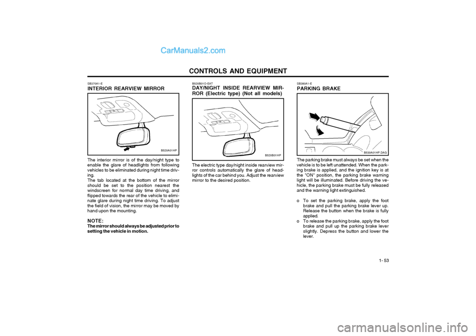
B520B01O-EAT DAY/NIGHT INSIDE REARVIEW MIR- ROR (Electric type) (Not all models) The electric type day/night inside rearview mir-
ror controls automatically the glare of head- lights of the car behind you. Adjust the rearviewmirror to the desired position.
SB370A1-E INTERIOR REARVIEW MIRROR The interior mirror is of the day/night type to
enable the glare of headlights from following vehicles to be eliminated during night time driv-ing.
The tab located at the bottom of the mirror
should be set to the position nearest thewindscreen for normal day time driving, andflipped towards the rear of the vehicle to elimi-nate glare during night time driving. To adjustthe field of vision, the mirror may be moved byhand upon the mounting. NOTE: The mirror should always be adjusted prior tosetting the vehicle in motion.
B520A01HPB520B01HP
SB380A1-E PARKING BRAKE The parking brake must always be set when the
vehicle is to be left unattended. When the park- ing brake is applied, and the ignition key is atthe "ON" position, the parking brake warninglight will be illuminated. Before driving the ve-hicle, the parking brake must be fully releasedand the warning light extinguished.
o To set the parking brake, apply the foot brake and pull the parking brake lever up. Release the button when the brake is fullyapplied.
o To release the parking brake, apply the foot brake and pull up the parking brake leverslightly. Depress the button and lower thelever.
B530A01HP.DAG
Page 347 of 349

INDEX10-3
M Maintenance Requirements
Explanation of scheduled maintenance items ........................ 5-6 ~ 5-8
Maintenance and servicing requirements ....................................... 5-1
Maintenance under severe usage conditions ................................. 5-5
Regular servicing ................................................................... 5-2 ~ 5-4
Mirrors Day/night inside rearview .............................................................. 1-53
Outside rearview ........................................................................... 1-51
Multi Function Switch
Headlight flash .............................................................................. 1-42
High and low beam ....................................................................... 1-42
Lane change signal ....................................................................... 1-41
Lighting switch ............................................................................... 1-42
Sidelight auto cut .......................................................................... 1-42
Turn signal operation .................................................................... 1-41
OOdometer .......................................................................................... 1-40
P Parking Brake ................................................................................... 1-53
Part-time 4WD Operation ......................................................... 2-9 ~ 2-11
Power Driver's Seat .......................................................................... 1-12
Power Outlet ..................................................................................... 1-46
Power Steering Fluid Level ............. ..................................................6-19
I Ignition Switch
..................................................................................... 2-2
Immobiliser System .................................................................... 1-2 ~ 1-4
Key ........................................................................................... 1-2, 1-4
Indicator and Warning Lights ................................................. 1-35 ~ 1-38
Instrument Cluster and Indicator ............................................ 1-31 ~ 1-34
Instruments and Controls ................ ..................................................1-30
Intermittent Wipe Facilit .................................................................... 1-44
J Jump Starting ...................................................................................... 3-2
K
Key ............................................................................................... 1-2, 1-4 If you lose your keys .................................................................... 3-11
Positions .......................................................................................... 2-2
LLimited-Slip Differential ..................................................................... 2-14
Luggage Compartment Cargo Security Screen .................................................................. 1-55
Light ............................................................................................... 1-54
Net ................................................................................................. 1-54