2003 Hyundai Terracan glove box
[x] Cancel search: glove boxPage 161 of 349

DO-IT-YOURSELF MAINTENANCE 6-15
anymore than 8.0 mm. If you have the instru- ments to check it with a force of 98N (22 lb.), the deflection should be approx. 8.0 mm (0.315 inches). If the belt is too loose, have it adjusted by your Hyundai dealer. NOTE: The compressor drive belt tension for diesel engine (2.9 CRDi only) is adjusted automati- cally.
B145A01HP-GAT CHANGING THE AIR FILTER (For Evaporator and Blower Unit) (If installed) The air filter is located in front of the evaporator unit behind the glove box. It helps to decrease pollutants from entering the car and to filter the air.
B760A01HP
Stopper
Diesel (2.5 TCI)
G140D01HP-GAT Checking the Compressor Drive Belt When the air conditioning is being used regular- ly, the compressor drive belt tension should be checked at least once a month. To check the drive belt tension, press down onthe belt halfway between the engine crankshaft and compressor pulleys. Pressing with your finger, you should not be able to deflect this belt
G140D01HP-D
G140D02HP
Gasoline
Generator pulley
Idler pulley Water pump pulley
COMP.pulley Auto tensionerCOMP. pulley
Crankshaft pulley Diesel (2.9 CRDi)
Crankshaft pulleyCOMP. pulleyCrankshaft pulley
Tension pulley
Tension pulley
G140B01A-AAT Checking the Air Conditioning Opera- tion
1. Start the engine and let it run at fast idle for
several minutes with the air conditioning set at the maximum cold setting.
2. If the air coming out of the in-dash vents is not cold, have the air conditioning systeminspected by your Hyundai dealer.
CAUTION:Running the air conditioning system forextended periods of time with a low refriger- ant level may damage the compressor. G140C01A-AAT LubricationTo lubricate the compressor and the seals in the system, the air conditioning should be run for at least 10 minutes each week. This is particularly important during cool weather when the air conditioning system is not otherwise in use.
Page 162 of 349

DO-IT-YOURSELF MAINTENANCE
6-16
B760A06HP
B760A07HP
6. Remove the filter cover by pulling the hook
of the filter cover.
7. Replace the air filter with a new one.
8. Installation is the reverse order of disassem- bly.
CAUTION:When installing the under cover, fit the cover
in the projection of blower assembly.
4. Remove the glove box mounting screws from the glove box assembly, and then de- tach the glove box assembly.
B760A04HP
B760A05HP
5. After removing the screws on the under cover, detach the under cover from the blower assembly by pushing the cover to- ward the engine room.
Blower assembly
Under cover
1. Open the glove box and remove the stop- pers by pushing the both sides of the glove box inward.
2. Lower the glove box down completely aftertaking out the damper strap from the hole.
3. Remove the lower instrument panel padmounting bolts (1) and screws (2), and then detach the lower instrument panel pad.
(1)
B760A02HP
B760A03HP
(2)
(1)
(2)
Page 183 of 349

INDEX
10-2
D Defrosting/Defogging
......................................................................... 1-70
Door
Locking, unlocking front door with a key ........................................ 1-6
Drink Holder ...................................................................................... 1-52
Drive Belts ............................................................................... 6-15, 6-18
Driving
Driving for economy ...................................................................... 2-13
Smooth cornering .......................................................................... 2-14
Winter driving ................................................................................ 2-14
E
Emission Control System ................................................................... 7-1
Engine
Before starting the engine ............................................................... 2-2
Compartment (3.5 V6) ..................................................................... 6-1
Compartment (2.5 TCI) ................................................................... 6-2
Compartment (2.9 CRDi) ................................................................ 6-3
Coolant ............................................................................................ 6-7
Coolant temperature gauge ........................................................... 1-42
If the engine overheats ................................................................... 3-2
Number ............................................................................................ 8-1
Oil .................................................................................................... 6-4Starting ............................................................................................ 2-3
Engine Exhaust Can Be Dangerous ................................................... 2-1
FFan Speed Control ................................................................... 1-66, 1-75 Fog Light
Front .............................................................................................. 1-47
Rear .............................................................................................. 1-47
Front Seats Adjustable front seats ................................................................... 1-11
Adjustable headrests ..................................................................... 1-12
Adjusting seat forward and rearward ............................................1-11
Adjusting seatback angle .............................................................. 1-11
Fuel Capacity .......................................................................................... 9-1
Gauge ............................................................................................ 1-42
Unleaded gasoline ........................................................................... 1-1
Fuel Filler Lid Remote release ............................................................................. 1-61
Full-time 4WD Operation ....................................................... 2-10 ~ 2-12
Fuses ................................................................................................ 6-18
GGeneral Checks .................................................................................. 6-4
Glove Box ......................................................................................... 1-55
HHazard Warning System ................................................................... 1-50
Headlight Aiming Adjustment ............................................................ 6-24
Headlight Leveling Device System ...................................................1-64
Heating and Ventilation Air flow control ......................................................... 1-67 ~ 1-68, 1-76
Temperature control ...................................................................... 1-68
Page 219 of 349
CONTROLS AND EQUIPMENT1- 25
tion key is turned to "ON" or if it remains illuminated after blinking for approxi-mately 6 seconds, or if it illuminates whilstthe vehicle is being driven, please havean authorized Hyundai dealer inspect thepre-tensioner seat belts and SRS airbagsystem as soon as possible.
WARNING:
o Pre-tensioners are designed to operate only one time. After activation, pre- tensioner seat belts must be replaced.All seat belts, of any type, should alwaysbe replaced after they have been wornduring a collision.
o The pre-tensioner seat belt assembly mechanisms become hot during activa-tion. Do not touch the pre-tensioner seatbelt assemblies for several minutes afterthey have been activated.
o Do not attempt to inspect or replace the pre-tensioner seat belts yourself. Thismust be done by an authorized Hyundaidealer.
o Do not strike the pre-tensioner seat belt assemblies.
o Do not attempt to service or repair the pre-tensioner seat belt system in anymanner.
o Improper handling of the pre-tensioner seat belt assemblies, and failure to heedthe warnings to not strike, modify, insp-ect, replace, service or repair the pre-tensioner seat belt assemblies may lead to improper operation or inadvertent ac-tivation and serious injury.
o Always wear seat belts when driving or riding in a motor vehicle.
NOTE:
o Both the driver's and front passenger's pre-tensioner seat belts will be activatedin certain frontal collisions. The pre-tensioner seat belts can be activated aloneor, where the frontal collision is severeenough, together with the airbags.
o When the pre-tensioner seat belts are activated, a loud noise may be heard andfine dust, which may appear to be smoke,may be visible in the passenger compart-ment. These are normal operating condi-tions and are not hazardous.
o Although it is harmless, the fine dust may cause skin irritation and should notbe breathed for prolonged periods. Washyour hands and face thoroughly after anaccident in which the pre-tensioner seatbelts were activated.
CAUTION:
o Because the sensor that activates the SRS airbag is connected with pre-tensioner seat belt, the SRS airbag warn-ing light on the instrument panel willblink for approximately 6 seconds afterthe ignition key has been turned to the"ON" position, and then it should turnoff.
o If pre-tensioner seat belt is not working properly, this warning light will illumi-nate even if there is no malfunction of theSRS airbag. If the SRS airbag warninglight does not illuminate when the igni-
AIR
BAG
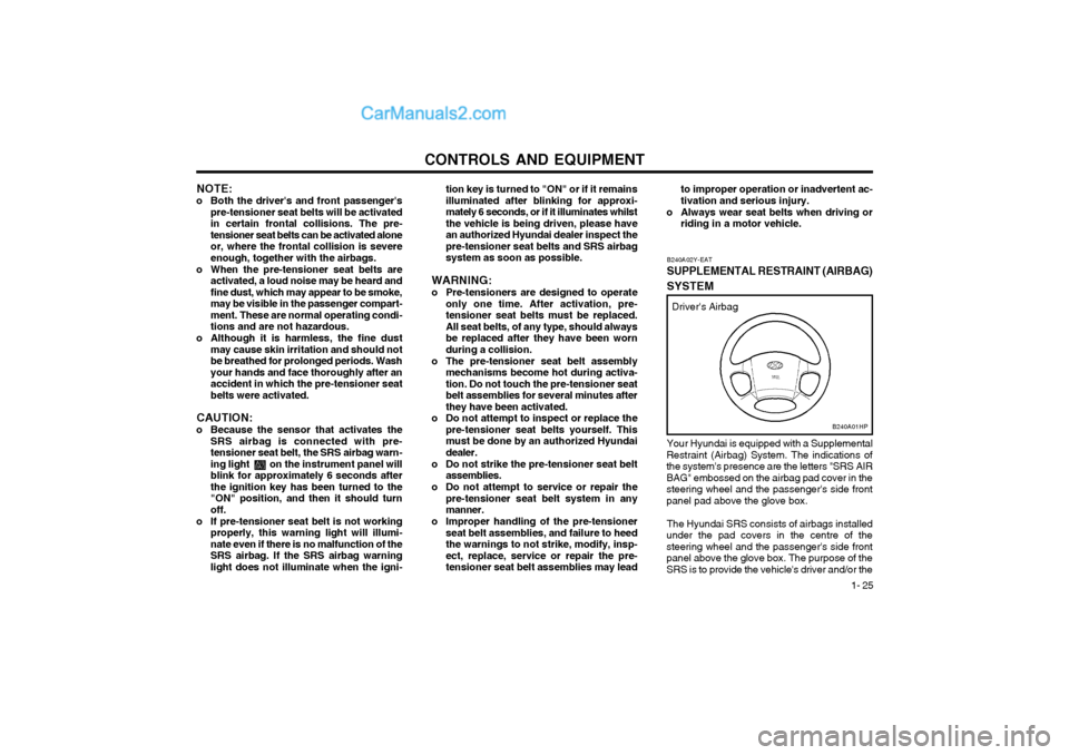
Your Hyundai is equipped with a Supplemental
Restraint (Airbag) System. The indications of the system's presence are the letters "SRS AIRBAG" embossed on the airbag pad cover in thesteering wheel and the passenger's side frontpanel pad above the glove box.
The Hyundai SRS consists of airbags installed
under the pad covers in the centre of thesteering wheel and the passenger's side frontpanel above the glove box. The purpose of theSRS is to provide the vehicle's driver and/or the
B240A01HP
Driver's Airbag
B240A02Y-EAT
SUPPLEMENTAL RESTRAINT (AIRBAG)
SYSTEM
Page 220 of 349

CONTROLS AND EQUIPMENT
1- 26 B240B02A-EAT SRS Components and Functions
B240B01L-D
The SRS consists of the following components:
- Driver's Airbag Module
- Passenger's Airbag Module
- Knee Bolster
- SRS Service Reminder Indicator (SRI)
- SRS Control Module (SRSCM)
The SRSCM continually monitors all elements whilst the ignition is "ON" to determine if afrontal or near-frontal impact is severe enoughto require airbag deployment.o Front airbags are not intended to deploy in side-impact, rear-impact or rollover crashes. In addition, airbags will not nor-mally deploy in frontal crashes below thedeployment threshold speed.
o For maximum safety protection in all types of crashes, all occupants includingthe driver should always wear their seatbelts whether or not an airbag is alsoprovided at their seating position to mini-mize the risk of severe injury or death inthe event of a crash. Do not sit or leanunnecessarily close to the airbag whilstthe vehicle is in motion.
o The SRS airbag system must deploy very rapidly to provide protection in a crash. Ifan occupant is out of position because ofnot wearing a seat belt, the airbag mayforcefully contact the occupant causingserious or fatal injuries.
front passenger with additional protection thanthat offered by the seat belt system alone, incase of a frontal impact of sufficient severity.
NOTE: Be sure to read information about the SRS
on the labels provided on the reverse of the sun visor and in the glove box.
WARNING:
o As its name implies, the SRS is designed to work with, and be supplemental to, thedriver's and the passenger's three pointseat belt systems and is not a substitutefor them. Therefore your seat belts mustbe worn at all times whilst the vehicle isin motion. The airbags deploy only incertain frontal impact conditions severeenough to likely cause significant injuryto the vehicle occupants.
o The SRS is designed to deploy the airbags only when an impact is sufficiently se-vere and when the impact angle is lessthan 30° from the forward longitudinalaxis of the vehicle and will not deploy inside, rear or rollover impacts. Addition-ally, the airbags will only deploy once.Thus, seat belts must be worn at alltimes.
o Front airbags are not intended to deploy in light collisions in which protection canbe provided by the seat belt alone.
B240C01HP
Rear impact
Side impact Rollover
Page 221 of 349

CONTROLS AND EQUIPMENT1- 27
Upon deployment, tear seams molded directly
into the pad covers will separate under pres- sure from the expansion of the airbags. Furtheropening of the covers then allows full inflation ofthe airbags.
A fully inflated airbag in combination with a
properly worn seat belt slows the driver's or thepassenger's forward motion, thus reducing the
risk of head or chest injury. After complete inflation, the airbag immediately
starts deflating, enabling the driver to maintain forward visibility.
B240B02L-D
The SRS service reminder indicator (SRI) on
the instrument panel will blink for about 6 sec- onds after the ignition key is turned to the "ON"position or after the engine is started, afterwhich the SRI should go out.
The airbag modules are located both in the
centre of the steering wheel and in the frontpassenger's panel above the glove box. Whenthe SRSCM detects a considerable impact tothe front of the vehicle, it will automaticallydeploy the airbags.B240B03L-D
CAUTION: When installing a container of liquid air
freshener inside a vehicle, do not place itnear the instrument cluster nor on the in-strument panel pad surface. If there is anyleakage from the air freshener onto theseareas (instrument cluster, instrument panelpad or air ventilator), it may damage theseparts. If the liquid from the air freshenerdoes leak onto these areas, wash them withwater immediately.
B240B01HP.DAG
Passenger's Airbag
Page 222 of 349

CONTROLS AND EQUIPMENT
1- 28 B240C01HP-GAT SRS CareThe SRS is virtually maintenance-free and so there are no parts you can safely service byyourself. The entire SRS system must be in-
spected by an authorized Hyundai dealer 10
years after the date that the vehicle was man-ufactured. Any work on the SRS system, such as remov-
ing, installing, repairing, or any work on thesteering wheel must be performed by a quali-fied Hyundai technician. Improper handling ofthe SRS system may result in serious personal injury.
WARNING:
o Extreme Hazard! Do not use a rearward facing restraint on a seat protected by an airbag in front of it!
o Modification to SRS components or wir- ing, including the addition of any kind ofbadges to the pad covers or modifica-tions to the body structure, can adverse-ly affect SRS performance and lead topossible injury.
o For cleaning the airbag pad covers, use only a soft, dry cloth or one which hasbeen moistened with plain water. Sol-vents or cleaners could adversely affectthe airbag covers and proper deploy-ment of the system.
o No objects should be placed over or near the airbag modules on the steering wheel,instrument panel, and the front passen-ger's panel above the glove box, becauseany such object could cause harm if the
YT10355A
Passenger's Airbag
B240B05L-D
WARNING:
o When the SRS is activated, there may be a loud noise and fine dust will be re- leased throughout the vehicle. These con-ditions are normal and are not hazard-ous. However, the fine dust generatedduring airbag deployment may cause skinirritation. Be sure to wash your handsand face thoroughly with lukewarm wa-ter and a mild soap after an accident inwhich the airbags were deployed.
o The SRS can function only when the ignition key is in the "ON" position. If theSRS SRI does not come on, or continu-ously remains on, after flashing for about6 seconds when the ignition key is turnedto the "ON" position, or after the engineis started, or comes on whilst driving, theSRS is not working properly. If this oc-curs, have your vehicle immediately in-spected by your Hyundai dealer. o Before you replace a fuse or disconnect
a battery terminal, turn the ignition key tothe "LOCK" position or remove the igni-tion key. Never remove or replace the airbag related fuse(s) when the ignition keyis in the "ON" position. Failure to heedthis warning will cause the SRS SRI toilluminate.
Page 224 of 349

CONTROLS AND EQUIPMENT
1- 30
B250A01HP-EAT INSTRUMENTS AND CONTROLS
1. Passenger's Airbag (Not all models)
2. Headlight Leveling Switch
3. Cruise Control Main Switch (Not all models)
4. Hazard Warning Switch
5. Panel Brightness Control Knob (Rheostat Switch)
6. Rear Fog Light Switch
7. Windscreen Wiper/Washer Switch 8. Horn and Driver's Airbag
9. Ignition Switch
10. Multi-Function Light Switch
/Front Fog Light Switch
11. Glove Box
12. Heating/Air Conditioning Control Panel
13. Seat Warmer Switch (Not all models)
14. Transfer Shift Knob CAUTION:When installing the container of liquid air
freshener inside a vehicle, do not place it near the instrument cluster nor on the in-strument panel pad surface. If there is anyleakage from the air freshener onto theseareas (Instrument cluster, instrument panelpad or air ventilator), it may damage these parts. If the liquid from the air freshener does leak onto these areas, wash them withwater immediately.
B250A01HP-E
21
15. Power Outlet
16. Shift Lever
17. Rear Window Wiper/Washer Switch(Not all models)
18. Ashtray
19. Remote Fuel-Filler Lid Release Lever
20. Steering Wheel Tilt Lever
21. Cruise Control Switch (Not all models)
22. Bonnet Release Lever
11 910
13 45
6 78
12 13 14 16 17 18 19 2022
2
15