2003 Hyundai Matrix door lock
[x] Cancel search: door lockPage 187 of 312

CONTROLS AND EQUIPMENT
1- 6 The system will be disarmed when the driver's or passenger's door is unlocked by depress-ing the "UNLOCK" button on the transmitter. After completion of the step above, the turn signal light will blink twice to indicate that thesystem is disarmed. NOTE: Once the system has been disarmed, it can not be rearmed except by repeating thearming procedures. CAUTION: Only the transmitter can disarm the armed stage. If the transmitter does not disarmthe system, it is necessary to take thefollowing steps;
1. Unlock the door with the key, which will
cause, the alarm to be activated.
2. Insert the key in the ignition key cylin- der and turn the ignition key to "ON" position.
3. Wait for 30 seconds. After completion of the steps above, the system will be disarmed. B070F01A-EAT Keyless Entry System (Not all models) Locking doors
1. Close all doors.
2. Push the "LOCK" button on the transmit-
ter.
3. At the same time all doors lock, the turn signal light will blink once to indicate that the system is armed.
Unlocking doors
1. Push the "UNLOCK" button on the trans- mitter.
2. At the same time all doors unlock, the turn signal light will blink twice to indicate that the system is disarmed.
B070E02HP-GAT Replacing the batteryWhen the transmitter's battery begins to get weak, it may take several pushes on thebutton to lock or unlock the doors, and theLED will not light. Replace the battery as soonas possible. Battery type : CR2032
B070C01FC-EAT Alarm Stage The alarm will be activated if any of the following occurs while the car is parked andthe system is armed.
1) A front or rear door is opened without using
the transmitter.
2) The tail gate is opened without using the transmitter.
3) The engine bonnet is opened.The alarming horn will sound and the turn signal lights will blink continuously for 27seconds. To turn off the system, unlock thedoor or tail gate with the transmitter.
B070D02O-AAT Disarmed Stage
3A9BA21
Page 189 of 312

CONTROLS AND EQUIPMENT
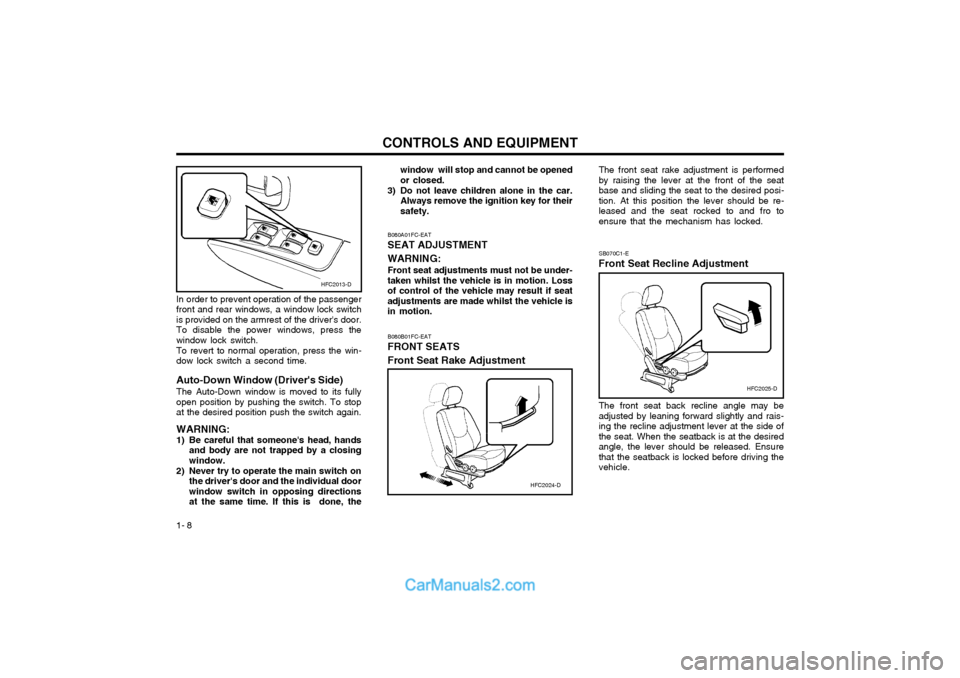
1- 8 The front seat rake adjustment is performed by raising the lever at the front of the seatbase and sliding the seat to the desired posi-tion. At this position the lever should be re-leased and the seat rocked to and fro toensure that the mechanism has locked. SB070C1-E
Front Seat Recline Adjustment
The front seat back recline angle may be adjusted by leaning forward slightly and rais-ing the recline adjustment lever at the side ofthe seat. When the seatback is at the desiredangle, the lever should be released. Ensurethat the seatback is locked before driving thevehicle.
B080B01FC-EAT FRONT SEATS Front Seat Rake Adjustment
HFC2024-D
HFC2025-D
B080A01FC-EAT SEAT ADJUSTMENT WARNING: Front seat adjustments must not be under- taken whilst the vehicle is in motion. Lossof control of the vehicle may result if seatadjustments are made whilst the vehicle isin motion. window will stop and cannot be openedor closed.
3) Do not leave children alone in the car. Always remove the ignition key for theirsafety.
In order to prevent operation of the passengerfront and rear windows, a window lock switchis provided on the armrest of the driver's door.To disable the power windows, press thewindow lock switch. To revert to normal operation, press the win- dow lock switch a second time. Auto-Down Window (Driver's Side) The Auto-Down window is moved to its fully open position by pushing the switch. To stopat the desired position push the switch again. WARNING:
1) Be careful that someone's head, hands and body are not trapped by a closing window.
2) Never try to operate the main switch on the driver's door and the individual doorwindow switch in opposing directionsat the same time. If this is done, the
HFC2013-D
Page 195 of 312

CONTROLS AND EQUIPMENT
1- 14 of movement whilst the belt is being worn. However, in the event of rapid deceleration orimpact, the belt mechanism will automaticallylock.
The mechanism will also lock if the seat belt
webbing is withdrawn too quickly when thebelt is being fastened or if attempts are madeto withdraw the webbing whilst the vehicle isnot on level ground. Should the seat belt lockunder these conditions, it will be possible torelease the mechanism by allowing a smallamount of webbing to be retracted and thebelt withdrawn again.
SSD1090Q
B200A01S-GAT
Adjusting Your Seat Belt
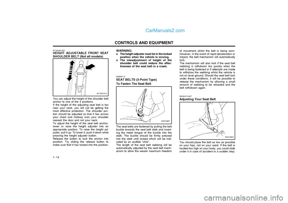
You should place the belt as low as possible
on your hips, not on your waist. If the belt is located too high on your body, you could slideunder it in case of accident or a sudden stop.
SB090P1-E
SEAT BELTS (3-Point Type) To Fasten The Seat Belt
SSD1090P
The seat belts are fastened by pulling the belt
buckle towards the seat belt stalk and insert- ing the metal tongue of the buckle into thestalk. The buckle should be firmly pressedinto the stalk until locked which will be indi-cated by an audible "click".
The length of the seat belt webbing will be
automatically adjusted by the seat belt mech-anism to allow the wearer maximum freedom WARNING:
o The height adjuster must be in the locked position when the vehicle is moving.
o The misadjustment of height of the shoulder belt could reduce the effec-tiveness of the seat belt in a crash.
B170A01E-D
B170A04A-EAT HEIGHT ADJUSTABLE FRONT SEAT SHOULDER BELT (Not all models) You can adjust the height of the shoulder belt anchor to one of the 4 positions. If the height of the adjusting seat belt is too near your neck, you will not be getting themost effective protection. The shoulder por-tion should be adjusted so that it lies acrossyour chest and midway over your shouldernearest the door and not your neck. To adjust the height of the seat belt anchor, lower or raise the height adjuster into anappropriate position. To raise the height ad-juster, pull it up. To lower it, push it down whilepressing the height adjuster button. Release the button to lock the anchor into position. Try sliding the release button tomake sure that it has locked into the position.
Page 196 of 312

1- 15
CONTROLS AND EQUIPMENT
SB090R1-F
To Release the Seat Belt
SSD1090R
The seat belt is released by pressing the
release button in the locking buckle.
When it is released, the belt should automati-
cally draw back into the retractor.
If this does not happen, check the belt to be
sure it is not twisted, then try again.
This could result of death, serious injury or property damage. Both arms should not beunder or over the belt. Rather, one should beover and the other under, as shown in theillustration.
Never wear the seat belt under the arm near-
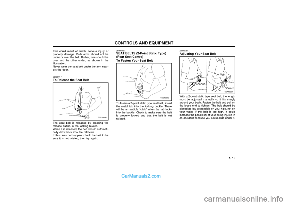
est the door. ZB090X2-A Adjusting Your Seat Belt
SSA1090T
Shorten
Correct
Too high
To fasten a 2-point static type seat belt, insert the metal tab into the locking buckle. Therewill be an audible "click" when the tab locksinto the buckle. Check to make sure the beltis properly locked and that the belt is nottwisted. With a 2-point static type seat belt, the length
must be adjusted manually so it fits snuglyaround your body. Fasten the belt and pull onthe loose end to tighten. The belt should beplaced as low as possible on your hips, not onyour waist. If the belt is too high, it couldincrease the possibility of your being injured inan accident because you could slide under it.
ZB090W2-A SEAT BELTS (2-Point Static Type) (Rear Seat Centre) To Fasten Your Seat Belt
SSD1090S
Page 205 of 312

CONTROLS AND EQUIPMENT
1- 24
YT10355A
WARNING:
o Do not install a child restraint system in the front passenger seat position.
A child restraint system must never be placed in the front seat. The infant orchild could be severely injured by anairbag deployment in case of an accident.
o Extreme Hazard! Do not use a rearward facing child restraint on a seat pro-tected by an airbag in front of it!
o Modification to SRS components or wir- ing, including the addition of any kindof badges to the pad covers or modifi-cations to the body structure, can ad-versely affect SRS performance and leadto possible injury.
WARNING:
o For best protection from the side airbag
system and to avoid being injured is by the deploying side impact airbag, both front seat occupants should sit in an upright position with the seat belt prop-erly fastened. The driver's hands shouldbe placed on the steering wheel at the9:00 and 3:00 o'clock positions. Thepassenger's arms and hands should beplaced in their laps.
o Do not use any accessory seat covers.
o Use of seat covers could reduce or prevent the effectiveness of the system.
o Do not install any accessories on the side or near the side impact airbag.
o Do not use excessive force on the side of the seat.
o Do not place any objects over the airbag or between the airbag and yourself. B240C03Y-GAT SRS Care The SRS is virtually maintenance-free and there are no parts you can safely service byyourself. The entire SRS system must beinspected by an authorized Hyundai dealer in10 years after the date that the vehicle wasmanufactured. Any work on the SRS system, such as remov- ing, installing, repairing, or any work on thesteering wheel must be performed by a quali-fied Hyundai technician. Improper handling ofthe SRS system may result in serious per-sonal injury.
HFC2092-DSide airbag sensor
o Do not place any objects (an umbrella,
bag, etc.) between the front door and the front seat. Such objects may be-come dangerous projectiles and causeinjury if the supplemental side impactair bag inflates.
o To prevent unexpected deployment of the side impact air bag that may resultin personal injury, avoid impact to theside airbag sensor when the ignitionkey is on.
Page 208 of 312

1- 27
CONTROLS AND EQUIPMENT
B260A01FC-EAT INSTRUMENT CLUSTER AND INDICATOR (GASOLINE ENGINE) 1. Temperature Gauge
2. Tachometer
3. Speedometer
4. Digital Clock
5. Odometer/Trip Odometer/Trip Computer
(Not all models)
6. Fuel Gauge
7. Turn Signal Indicator Light
8. Automatic Transaxle Position Indicator Light (Auto T/A only)
9. Immobilizer Warning Indicator Light
10. SRS (Airbag) Warning Light
11. Traction Control Indicator Light (Not all models)
12. Overdrive off Indicator Light (Not all models)
13. Parking Brake/Brake Fluid Level Warning Light
14. Charging System Warning Light
15. Low Fuel Warning Light
16. High Beam Indicator Light
17. Tail Gate Open Warning Light
18. Door Ajar Warning Light
19. Oil Pressure Warning Light
20. Malfunction Indicator Light (MIL)
21. ABS Warning Light (Not all models)
B260A01FC-1
1
2 3
45
6
7 8 910
11 12 13 14 15 16 17 18
1920 21
7
Page 209 of 312

CONTROLS AND EQUIPMENT
1- 28
B260B01FC-EAT INSTRUMENT CLUSTER AND INDICATOR (DIESEL ENGINE) 1. Temperature Gauge
2. Tachometer
3. Speedometer
4. Digital Clock
5. Odometer/Trip Odometer/Trip Computer
(Not all models)
6. Fuel Gauge
7. Fuel Filter Warning Light
8. Turn Signal Indicator Light
9. Immobilizer Warning Indicator Light
10. SRS (Airbag) Warning Light
11. Diesel Pre-heat Indicator Light
12. Traction Control Indicator Light
(Not all models)
13. Parking Brake/Brake Fluid Level Warning Light
14. Charging System Warning Light
15. Low Fuel Warning Light
16. High Beam Indicator Light
17. Tail Gate Open Warning Light
18. Door Ajar Warning Light
19. Oil Pressure Warning Light
20. Malfunction Indicator Light (MIL)
21. ABS Warning Light (Not all models)
B260B01FC-1
1 23 4 5
6
7 8
910
8
11 12
1314
15 16 17 18
19 20 21
Page 212 of 312

1- 31
CONTROLS AND EQUIPMENTSB210S1-E BRAKE PAD WEAR INDICATOR The front brake disc pads are fitted with an audible wear indicator which will cause a highpitched noise to be emitted when the remain-ing amount of friction lining is below the speci-fied value. When the wear indicator is heard,the brake pads should be replaced withoutdelay to avoid damage occurring to the brakediscs and a severe reduction in braking effi-ciency.
B260N02FC-EAT
MALFUNCTION INDICATOR LIGHT
This light illuminates when there is a malfunc- tion of an exhaust gas related component,and the system is not functioning properly sothat the exhaust gas regulation values are notsatisfied. This light will illuminate when theignition key is tuned to the "ON" position, andwill go out after the engine start. If it illumi-nates while driving, or does not illuminatewhen the ignition key is turned to the "ON"position, take your car to your nearest autho-rized Hyundai dealer and have the systemchecked.
B260S01B-GAT DIESEL PRE-HEAT INDICATOR LIGHT-AMBER(Diesel Engine)
The indicator light illuminates amber when the ignition switch is placed at the "ON" position.The engine can be started after the pre-heatindicator light goes off. The illuminating timevaries with the water temperature, air tem-perature and battery condition. NOTE: If the engine were not started 10 seconds after the preheating is completed, turn theignition key once more to the "LOCK"position, and then to the "ON" position, inorder to preheat again.
B265A01B-GAT FUEL FILTER WARNING LIGHT-RED (Diesel Engine)
This light illuminates when the ignition switch
is set to the "ON" position and goes off after the engine has started. If it lights up while theengine is running, it indicates that water hasaccumulated inside the fuel filter. If this hap-pens, remove the water from the fuel filter.
(Refer to "6-19 page")
B260C02E-EAT
TRACTION CONTROL INDICATOR LIGHT(Not all models)
The traction control indicator changes opera- tion according to the ignition switch positionand whether or not the system is in operation. It will also illuminate when the ignition key is turned to the "ON" position, and then go off ina few seconds. If the TCS indicator stays on,take your car to your authorized Hyundaidealer and have the system checked. Seesection 2 for more information about the TCSsystem.
B270B02O-EAT
PARKING START WARNING SOUND (Not all models)
If the vehicle is driven at 6mph(10km/h) for
more than 2~3 seconds, the warning chime will sound continuously when the parking brake engaged.
B900A01A-EAT ACOUSTIC WARNING SOUND (Not all models) The acoustic warning chime sounds when the tail lights are on and the door in driver side isopen. This prevents the battery from dis-charging when the car is left with the tail lightson. The chime sounds until the tail lights areturned off.