2003 Hyundai H-1 (Grand Starex) fuel
[x] Cancel search: fuelPage 139 of 173
PREVENTIVE MAINTENANCE
PREVENTIVE MAINTENANCE PREVENTIVE MAINTENANCE
PREVENTIVE MAINTENANCE
PREVENTIVE MAINTENANCE
6-2 90 72
RR R I I I
DESCRIPTION
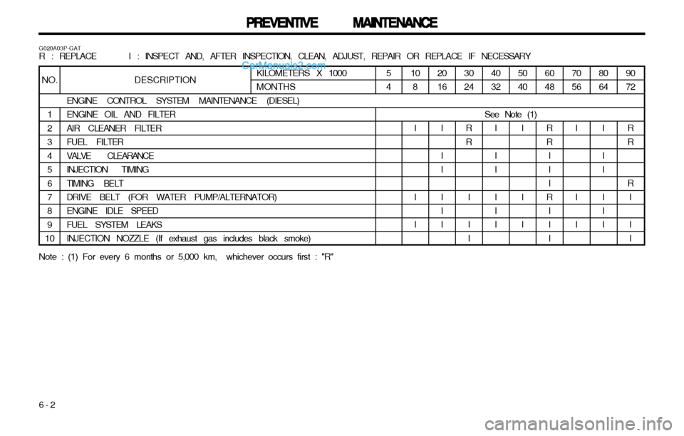
ENGINE CONTROL SYSTEM MAINTENANCE (DIESEL) ENGINE OIL AND FILTER AIR CLEANER FILTERFUEL FILTERVALVE CLEARANCEINJECTION TIMINGTIMING BELT DRIVE BELT (FOR WATER PUMP/ALTERNATOR) ENGINE IDLE SPEEDFUEL SYSTEM LEAKSINJECTION NOZZLE (If exhaust gas includes black smoke)
G020A03P-GAT R : REPLACE I : INSPECT AND, AFTER INSPECTION, CLEAN, ADJUST, REPAIR OR REPLACE IF NECESSARY
80 64
I I I I I I
KILOMETERS X 1000MONTHSNO.
1 23456 7 89
10
Note : (1) For every 6 months or 5,000 km, whichever occurs first : "R" 10
8
I I I 20 16
I I I I I I 3024
RR
I I I 4032
I I I I I I 5040
I I I 60 48
RR III
R III 7056
I I I
5 4
See Note (1)
Page 141 of 173
PREVENTIVE MAINTENANCE
PREVENTIVE MAINTENANCE PREVENTIVE MAINTENANCE
PREVENTIVE MAINTENANCE
PREVENTIVE MAINTENANCE
6-4 DESCRIPTION
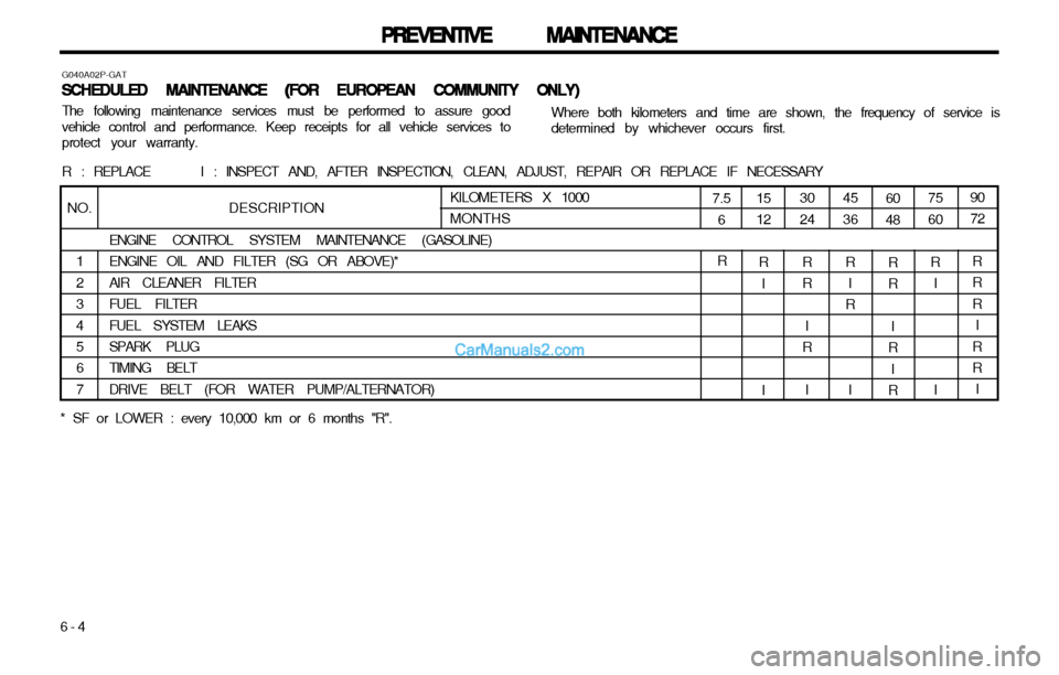
ENGINE CONTROL SYSTEM MAINTENANCE (GASOLINE) ENGINE OIL AND FILTER (SG OR ABOVE)*AIR CLEANER FILTERFUEL FILTERFUEL SYSTEM LEAKSSPARK PLUG TIMING BELT DRIVE BELT (FOR WATER PUMP/ALTERNATOR)
G040A02P-GAT
SCHEDULED MAINTENANCE (FOR EUROPEAN COMMUNITY ONLY)
SCHEDULED MAINTENANCE (FOR EUROPEAN COMMUNITY ONLY) SCHEDULED MAINTENANCE (FOR EUROPEAN COMMUNITY ONLY)
SCHEDULED MAINTENANCE (FOR EUROPEAN COMMUNITY ONLY)
SCHEDULED MAINTENANCE (FOR EUROPEAN COMMUNITY ONLY)
Where both kilometers and time are shown, the frequency of service is determined by whichever occurs first.
The following maintenance services must be performed to assure goodvehicle control and performance. Keep receipts for all vehicle services toprotect your warranty. R : REPLACE I : INSPECT AND, AFTER INSPECTION, CLEAN, ADJUST, REPAIR OR REPLACE IF NECESSARY
NO.
1 2345 6 7KILOMETERS X 1000 MONTHS
* SF or LOWER : every 10,000 km or 6 months "R".
R
7.5 6 90 72
RRR I
RR I
15 12
R I I 30 24
RR I
R
I 4536
R I
R
I 6048
RR I
R I
R 7560
R I I
Page 142 of 173
6-5
PREVENTIVE MAINTENANCE
PREVENTIVE MAINTENANCE PREVENTIVE MAINTENANCE
PREVENTIVE MAINTENANCE
PREVENTIVE MAINTENANCE
90 72R R I
R II
R II I
DESCRIPTION
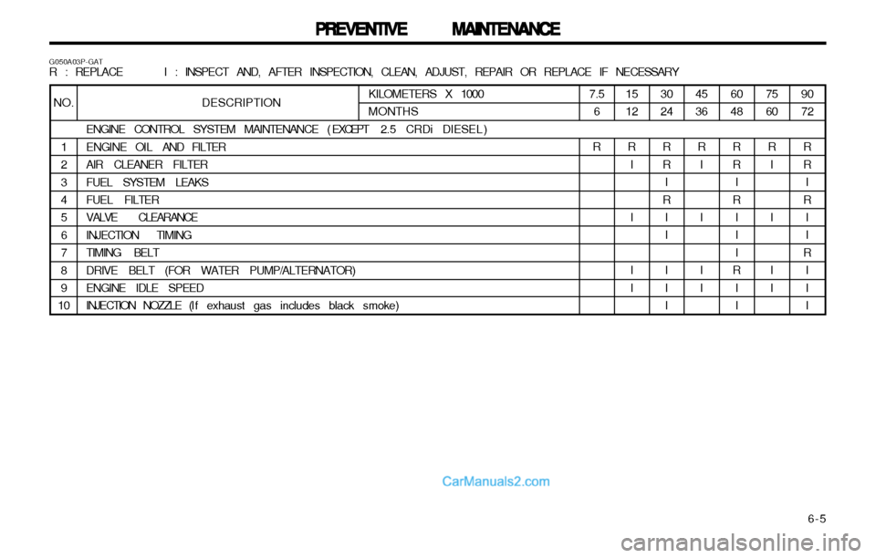
ENGINE CONTROL SYSTEM MAINTENANCE ( EXCEPT 2.5 CRDi DIESEL )
ENGINE OIL AND FILTER
AIR CLEANER FILTER FUEL SYSTEM LEAKS FUEL FILTER VALVE CLEARANCEINJECTION TIMINGTIMING BELTDRIVE BELT (FOR WATER PUMP/ALTERNATOR) ENGINE IDLE SPEED
INJECTION NOZZLE (I f exhaust gas includes black smoke)
G050A03P-GAT R : REPLACE I : INSPECT AND, AFTER INSPECTION, CLEAN, ADJUST, REPAIR OR REPLACE IF NECESSARY
NO.
1 23 4 5678 9
10KILOMETERS X 1000 MONTHS75 60
R I I I I
60 48
R R I
R III
R I I
4536
R I I I I
30 24
R R I
R II I I I
1512
R I I I I
7.5
6
R
Page 143 of 173

PREVENTIVE MAINTENANCE
PREVENTIVE MAINTENANCE PREVENTIVE MAINTENANCE
PREVENTIVE MAINTENANCE
PREVENTIVE MAINTENANCE
6-6 90 72
RRR I
RR I
DESCRIPTION
ENGINE CONTROL SYSTEM MAINTENANCE (2.5 CRD i DIESEL ONLY)
ENGINE OILENGINE OIL FILTERAIR CLEANER FILTERFUEL SYSTEM LEAKSFUEL FILTER DRIVE BELT (FOR WATER PUMP/ALTERNATOR)
INJECTION NOZZLE (I f exhaust gas includes black smoke)
G080A01P-GAT R : REPLACE I : INSPECT AND, AFTER INSPECTION, CLEAN, ADJUST, REPAIR OR REPLACE IF NECESSARY
NO.
1 2345 6 7KILOMETERS X 1000 MONTHS75 60RR I
6048
RRR I
R I I
45 36
RR I
3024
RRR I
R
I I
15 12
RR I
Page 146 of 173
6-9
PREVENTIVE MAINTENANCE
PREVENTIVE MAINTENANCE PREVENTIVE MAINTENANCE
PREVENTIVE MAINTENANCE
PREVENTIVE MAINTENANCE
G080F01P-GAToo
oo
o
Fuel hose, vapor hose and fuel
Fuel hose, vapor hose and fuel Fuel hose, vapor hose and fuel
Fuel hose, vapor hose and fuel
Fuel hose, vapor hose and fuel
filler cap
filler cap filler cap
filler cap
filler cap
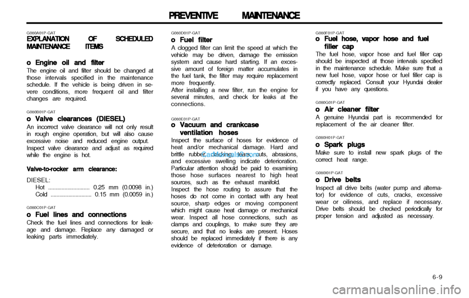
The fuel hose, vapor hose and fuel filler cap
should be inspected at those intervals specified in the maintenance schedule. Make sure that anew fuel hose, vapor hose or fuel filler cap iscorrectly replaced. Consult your Hyundai dealerif you have any questions.
G080G01P-GAToo
oo
o Air cleaner filter
Air cleaner filter Air cleaner filter
Air cleaner filter
Air cleaner filter
A genuine Hyundai part is recommended forreplacement of the air cleaner filter. G080H01P-GAT
oo
oo
o Spark plugs
Spark plugs Spark plugs
Spark plugs
Spark plugs
Make sure to install new spark plugs of the correct heat range. G080I01P-GAT
oo
oo
o
Drive belts
Drive belts Drive belts
Drive belts
Drive belts
Inspect all drive belts (water pump and alterna- tor) for evidence of cuts, cracks, excessivewear or oiliness, and replace if necessary.Drive belts should be checked periodically forproper tension and adjusted as necessary.
G080D01P-GAT
oo
oo
o Fuel filter
Fuel filter Fuel filter
Fuel filter
Fuel filter
A clogged filter can limit the speed at which the
vehicle may be driven, damage the emissionsystem and cause hard starting. If an exces-sive amount of foreign matter accumulates inthe fuel tank, the filter may require replacementmore frequently.
After installing a new filter, run the engine for
several minutes, and check for leaks at theconnections.
G080A01P-GAT
EXPLANATION OF SCHEDULED
EXPLANATION OF SCHEDULED EXPLANATION OF SCHEDULED
EXPLANATION OF SCHEDULED
EXPLANATION OF SCHEDULED
MAINTENANCE ITEMS
MAINTENANCE ITEMS MAINTENANCE ITEMS
MAINTENANCE ITEMS
MAINTENANCE ITEMS
oo
oo
o
Engine oil and filter
Engine oil and filter Engine oil and filter
Engine oil and filter
Engine oil and filter
The engine oil and filter should be changed at
those intervals specified in the maintenanceschedule. If the vehicle is being driven in se-vere conditions, more frequent oil and filterchanges are required.
G080B01P-GAT oo
oo
o Valve clearances (DIESEL)
Valve clearances (DIESEL) Valve clearances (DIESEL)
Valve clearances (DIESEL)
Valve clearances (DIESEL)
An incorrect valve clearance will not only result
in rough engine operation, but will also causeexcessive noise and reduced engine output.
Inspect valve clearance and adjust as required
while the engine is hot.
Valve-to-rocker arm clearance:
Valve-to-rocker arm clearance: Valve-to-rocker arm clearance:
Valve-to-rocker arm clearance:
Valve-to-rocker arm clearance: DIESEL:
Hot ............................ 0.25 mm (0.0098 in.) Cold ............................ 0.15 mm (0.0059 in.)
G080C01P-GAT oo
oo
o Fuel lines and connections
Fuel lines and connections Fuel lines and connections
Fuel lines and connections
Fuel lines and connections
Check the fuel lines and connections for leak-
age and damage. Replace any damaged or leaking parts immediately. G080E01P-GAT
oo
oo
o Vacuum and crankcase
Vacuum and crankcase Vacuum and crankcase
Vacuum and crankcase
Vacuum and crankcase
ventilation hoses
ventilation hoses ventilation hoses
ventilation hoses
ventilation hoses
Inspect the surface of hoses for evidence of
heat and/or mechanical damage. Hard andbrittle rubber, cracking, tears, cuts, abrasions,and excessive swelling indicate deterioration.Particular attention should be paid to examiningthose hose surfaces nearest to high heatsources, such as the exhaust manifold.
Inspect the hose routing to assure that the
hoses do not come in contact with any heatsource, sharp edges or moving componentwhich might cause heat damage or mechanicalwear. Inspect all hose connections, such asclamps and couplings, to make sure they aresecure, and that no leaks are present. Hosesshould be replaced immediately if there is anyevidence of deterioration or damage.
Page 148 of 173
7-1
EMISSION CONTROL SYSTEM
EMISSION CONTROL SYSTEM EMISSION CONTROL SYSTEM
EMISSION CONTROL SYSTEM
EMISSION CONTROL SYSTEM
H030A01P-GAT2.2.
2.2.
2.
EE
EE
E
VAPORATIVE
VAPORATIVE VAPORATIVE
VAPORATIVE
VAPORATIVE E
E E
E
E MISSION CON-
MISSION CON- MISSION CON-
MISSION CON-
MISSION CON-
TROL
TROL TROL
TROL
TROL SS
SS
S YSTEM
YSTEM YSTEM
YSTEM
YSTEM (
( (
(
( EE
EE
E xcept canister)
xcept canister) xcept canister)
xcept canister)
xcept canister)
The Evaporative Emission Control System is
designed to prevent fuel vapors from escaping into the atmosphere.
If the fuel-vapor vent line is clogged or dam-
aged, the fuel-vapor mixture will escape intothe atmosphere and cause insufficient emis-sion control. Disconnect the line at both ends, and blow it
clean with compressed air.
Remove the filler cap from the filler pipe, and
check to see if there is evidence that thepacking contact to the filler pipe is faulty. Theoverfill limiter (2-way valve) installed on thevapor line between the canister inlet and fueltank outlet must be checked for correct opera-tion. H050A01P-GAT
3.3.
3.3.
3.
EXHAUST EMISSION CONTROL
EXHAUST EMISSION CONTROL EXHAUST EMISSION CONTROL
EXHAUST EMISSION CONTROL
EXHAUST EMISSION CONTROL
SYSTEM
SYSTEM SYSTEM
SYSTEM
SYSTEM
The Exhaust Emission Control System is a
highly effective system which controls exhaustemission while maintaining good vehicle per-formance.
H060A01P-GATCC
CC
C
atalytic Converter
atalytic Converter atalytic Converter
atalytic Converter
atalytic Converter
All Hyundai vehicles are equipped with a mono-
lith type three-way catalytic converter to re-duce the carbon monoxide, hydrocarbons andnitrogen oxides contained in the exhaust gas.
H000A01P-GAT
7.7.
7.7.
7.
EMISSION CON-
EMISSION CON- EMISSION CON-
EMISSION CON-
EMISSION CON-
TROL SYSTEM
TROL SYSTEM TROL SYSTEM
TROL SYSTEM
TROL SYSTEM
H010A01P-GAT EMISSION CONTROL SYSTEM
EMISSION CONTROL SYSTEM EMISSION CONTROL SYSTEM
EMISSION CONTROL SYSTEM
EMISSION CONTROL SYSTEM
(Gasoline)
(Gasoline) (Gasoline)
(Gasoline)
(Gasoline) Your Hyundai is equipped with an emission
control system. There are three emission control systems which
are as follows.
(1) Crankcase emission control system (2) Evaporative emission control system(3) Exhaust emission control system In order to assure the proper function of the
emission control systems, it is recommended that you have your vehicle inspected and main-tained by an authorized Hyundai dealer in ac-cordance with the maintenance schedule inthis manual.
H020A01P-GAT1.1.
1.1.
1.
CRANKCASE EMISSION CONTROL
CRANKCASE EMISSION CONTROL CRANKCASE EMISSION CONTROL
CRANKCASE EMISSION CONTROL
CRANKCASE EMISSION CONTROL
SYSTEM
SYSTEM SYSTEM
SYSTEM
SYSTEM
The positive crankcase ventilation system is
employed to prevent air pollution caused byblow-by gases being emitted from the crank-case. This system supplies fresh air to thecrankcase through the air cleaner. Inside thecrankcase, the fresh air mixes with blow-bygases, then passes through the PCV valve intothe induction system. H080A01P-GAT
PCV Valve
PCV Valve PCV Valve
PCV Valve
PCV Valve
The crankcase ventilation system must be kept
clean to maintain good engine performance.
Periodic servicing is required to remove com-
bustion products from the PCV valve. H040A01P-GAT
Canister
Canister Canister
Canister
Canister While the engine is inoperative, fuel vapors
generated inside the fuel tank are absorbed and stored in the canister. When the engine isrunning, the fuel vapors absorbed in the canis-ter are drawn into the induction system throughthe purge control solenoid valve.
H090A01P-GATPurge Control Solenoid Valve
Purge Control Solenoid Valve Purge Control Solenoid Valve
Purge Control Solenoid Valve
Purge Control Solenoid Valve
The purge control solenoid valve is controlled
by the ECU; when the engine coolant tempera-ture is low, and during idling, it closes, so thatevaporated fuel is not taken into the surge tank.After engine warm-up, during ordinary driving, it opens so as to introduce evaporated fuel to the surge tank.
77
77
7
Page 149 of 173

EMISSION CONTROL SYSTEM
EMISSION CONTROL SYSTEM EMISSION CONTROL SYSTEM
EMISSION CONTROL SYSTEM
EMISSION CONTROL SYSTEM
7-2
H100A01P-GAT
Vacuum Hoses, Crankcase Ventilation
Vacuum Hoses, Crankcase Ventilation Vacuum Hoses, Crankcase Ventilation
Vacuum Hoses, Crankcase Ventilation
Vacuum Hoses, Crankcase Ventilation
Hoses and Water Hoses
Hoses and Water Hoses Hoses and Water Hoses
Hoses and Water Hoses
Hoses and Water Hoses Inspect the surface of hoses for evidence of heat and mechanical damage. Hard and brittle rubber, cracking, checking, tears, cuts, abrasions, and excessive swellingindicate deterioration of the rubber.Particular attention should be paid to examin-ing those surfaces nearest to high heat sources,such as the exhaust manifold. Inspect the hose routing to assure that the hoses do not come in contact with any heatsource or moving component which might causeheat damage or mechanical wear. Inspect allhose connections, such as clamps and cou-plings, to make sure they are secure and thatno leaks are present. Hoses should be re-placed immediately if there is any evidence ofdeterioration or damage. H110A01P-GAT
Fuel System (tank, pipe line, connec-
Fuel System (tank, pipe line, connec- Fuel System (tank, pipe line, connec-
Fuel System (tank, pipe line, connec-
Fuel System (tank, pipe line, connec-
tions and fuel filler cap)
tions and fuel filler cap) tions and fuel filler cap)
tions and fuel filler cap)
tions and fuel filler cap)
Check for damage or leakage in the fuel lines
and connections. Check for damage and loose-ness of fuel filler cap. Particular attention shouldbe paid to examine those fuel lines nearest tohigh heat sources such as the exhaust mani-fold.
H120A01P-GATDistributor Cap, Rotor and Spark Ad-
Distributor Cap, Rotor and Spark Ad- Distributor Cap, Rotor and Spark Ad-
Distributor Cap, Rotor and Spark Ad-
Distributor Cap, Rotor and Spark Ad-
vancer System
vancer System vancer System
vancer System
vancer System
Check the distributor cap, rotor and spark ad-
vancer system to maintain driveability and goodexhaust gas.
Page 156 of 173
8-7
CONSUMER INFORMATION
CONSUMER INFORMATION CONSUMER INFORMATION
CONSUMER INFORMATION
CONSUMER INFORMATION
( 9 ) Fuel, engine coolant, oil and exhaust gas leakage
(10) Exterior and interior lamp operation (11) Meter, gauge, and indication/warning lamp operation
(12) Steering wheel free play(13) Clutch pedal free play (14) Brake pedal free play (15) Parking brake lever stroke
Others
Others Others
Others
Others
(1) Wheel rotation
(1) Wheel rotation (1) Wheel rotation
(1) Wheel rotation
(1) Wheel rotation
Every 20,000km (12,000miles)or 12
Every 20,000km (12,000miles)or 12 Every 20,000km (12,000miles)or 12
Every 20,000km (12,000miles)or 12
Every 20,000km (12,000miles)or 12
months, whichever comes first
months, whichever comes first months, whichever comes first
months, whichever comes first
months, whichever comes first
(2) Hinge and latch lubrication
(2) Hinge and latch lubrication (2) Hinge and latch lubrication
(2) Hinge and latch lubrication
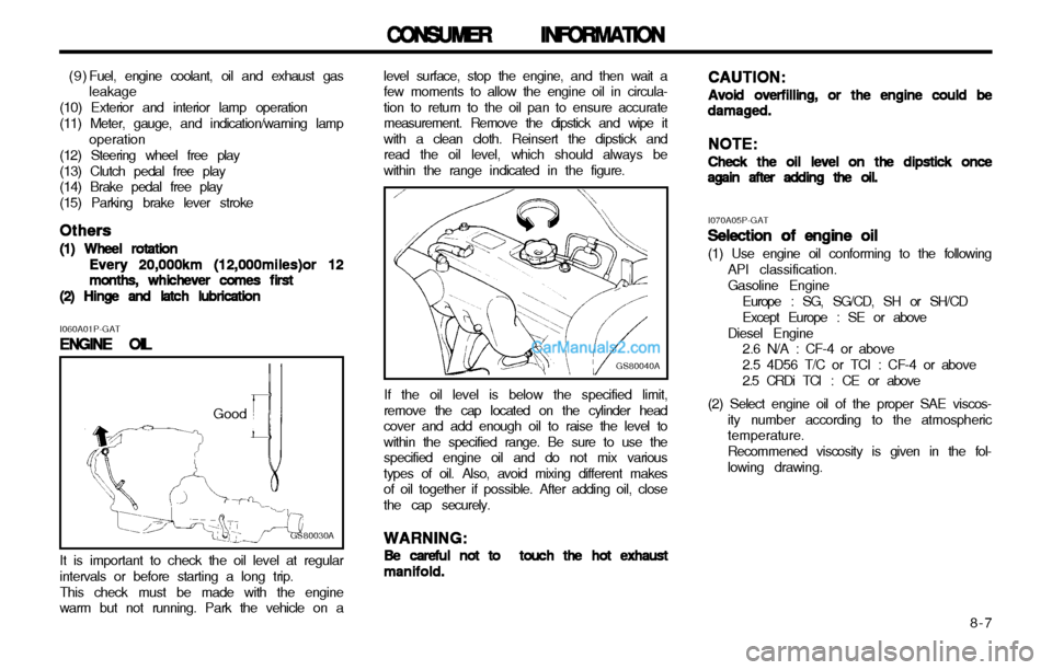
(2) Hinge and latch lubrication level surface, stop the engine, and then wait a few moments to allow the engine oil in circula-tion to return to the oil pan to ensure accuratemeasurement. Remove the dipstick and wipe itwith a clean cloth. Reinsert the dipstick andread the oil level, which should always bewithin the range indicated in the figure.
GS80030A
Good
I060A01P-GAT
ENGINE OIL
ENGINE OIL ENGINE OIL
ENGINE OIL
ENGINE OIL
It is important to check the oil level at regular
intervals or before starting a long trip.
This check must be made with the engine
warm but not running. Park the vehicle on a
GS80040A
If the oil level is below the specified limit,
remove the cap located on the cylinder head cover and add enough oil to raise the level towithin the specified range. Be sure to use thespecified engine oil and do not mix varioustypes of oil. Also, avoid mixing different makesof oil together if possible. After adding oil, closethe cap securely.
WARNING:
WARNING: WARNING:
WARNING:
WARNING:
Be careful not to touch the hot exhaust
Be careful not to touch the hot exhaust Be careful not to touch the hot exhaust
Be careful not to touch the hot exhaust
Be careful not to touch the hot exhaust manifold.
manifold. manifold.
manifold.
manifold. CAUTION:
CAUTION: CAUTION:
CAUTION:
CAUTION:
Avoid overfilling, or the engine could be
Avoid overfilling, or the engine could be Avoid overfilling, or the engine could be
Avoid overfilling, or the engine could be
Avoid overfilling, or the engine could bedamaged.
damaged. damaged.
damaged.
damaged.
NOTE:
NOTE: NOTE:
NOTE:
NOTE:
Check the oil level on the dipstick once
Check the oil level on the dipstick once Check the oil level on the dipstick once
Check the oil level on the dipstick once
Check the oil level on the dipstick onceagain after adding the oil.
again after adding the oil. again after adding the oil.
again after adding the oil.
again after adding the oil.
I070A05P-GATSelection of engine oil
Selection of engine oil Selection of engine oil
Selection of engine oil
Selection of engine oil (1) Use engine oil conforming to the following
API classification. Gasoline Engine
Europe : SG, SG/CD, SH or SH/CDExcept Europe : SE or above
Diesel Engine 2.6 N/A : CF-4 or above2.5 4D56 T/C or TCI : CF-4 or above
2.5 CRDi TCI : CE or above
(2) Select engine oil of the proper SAE viscos- ity number according to the atmospheric temperature. Recommened viscosity is given in the fol- lowing drawing.