2003 Hyundai Grandeur lights
[x] Cancel search: lightsPage 157 of 235

WHAT TO DO IN AN EMERGENCY 3- 3
WARNING:
The gas produced by the battery during the jump-start operation is highly explosive. If these instruc- tions are not followed exactly, seri-ous personal injury and damage to the vehicle may occur! If you are not sure how to follow this proce-dure, seek qualified assistance. Automobile batteries contain sul- furic acid. This is poisonous andhighly corrosive. When jump start- ing, wear protective glasses and be careful not to get acid on yourself,your clothing or on the car.
o If you should accidentally get acid on your skin or in your eyes, imme- diately remove any contaminatedclothing and flush the area with clear water for at least 15 minutes. Then promptly obtain medical attention. Ifyou must be transported to an emer- gency facility, continue to apply water to the affected area with a spongeor cloth. o The gas produced by the battery
during the jump-start operation ishighly explosive. Do not smoke orallow a spark or open flame in the vicinity.
o The battery being used to provide the jump start must be 12-volt. If youcannot determine that it is a 12-volt battery, do not attempt to use it forthe jump start.
o To jump start a car with a discharged
battery, follow this procedure ex-actly:
1. If the booster battery is installed in another vehicle, be sure the two vehicles are not touching.
2. Turn off all unnecessary lights and accessories in both vehicles.
3. Attach the clamps of the jumper
cable in the exact order shown in the illustration. That is, first, attach one clamp of the jumper cable to the positive (+) post or cable of thedischarged battery. Then attach the other end of the same cable to the positive (+) post or cable of thebooster battery. Next, using the other cable, attach one clamp to the negative (-) post or cable of the booster battery. Then attach the other end of that cable to a solid metal part of the engine away fromthe battery. Do not connect the cable to any moving part.
4. Start the engine in the car with the booster battery and let it run for afew minutes. This will help to as- sure that the booster battery is fullycharged. During the jumping opera- tion, run the engine in this vehicle at about 2,000 rpm.
5. Start the engine in the car with the discharged battery using the nor-mal starting procedure. After theengine starts, leave the jumper cables connected and let the engine run at fast idle or about 2,000 rpmfor several minutes.
6. Carefully remove the jumper cables
in the reverse order of attachment.
If you do not know why your batterybecame discharged (because the lightswere left on, etc.), have the charging system checked by your Hyundai dealer.!
Page 186 of 235

DO-IT-YOURSELF MAINTENANCE 6- 5
G020A02A-AAT
GENERAL CHECKS Engine Compartment
The following should be checked regu- larly:
o Engine oil level and condition
o Transaxle fluid level and condition
o Brake fluid level
o Clutch fluid level
o Coolant level
o Windshield washer fluid level
o Accessory drive belt condition
o Coolant hose condition
o Fluid leaks (on or below compo- nents)
o Power steering fluid level and con-
dition
o Battery condition
o Air filter condition G020C01A-AAT Vehicle Interior The following should be checked each time when the vehicle is driven:
o Lights operation
o Windshield wiper operation
o Horn operation
o Defroster, heater system operation
(and air conditioning, if installed)
o Steering operation and condition
o Mirror condition and operation
o Turn signal operation
o Accelerator pedal operation
o Brake operation, including parking brake
o Manual transaxle operation, includ- ing clutch operation
o Automatic transaxle operation, in- cluding "Park" mechanism opera-tion
o Seat control condition and opera- tion
o Seat belt condition and operation
o Sunvisor operation If you notice anything that does not operate correctly or appears to befunctioning incorrectly, inspect it care- fully and seek assistance from your Hyundai dealer if service is needed.
G020B01A-AAT
Vehicle Exterior
The following should be checked
monthly:
o Overall appearance and condition
o Wheel condition and wheel nut torgue
o Exhaust system condition
o Light condition and operation
o Windshield glass condition
o Wiper blade condition
o Paint condition and body corrosion
o Fluid leaks
o Door and hood lock condition
o Tire pressure and condition (including spare tire)
Page 202 of 235
DO-IT-YOURSELF MAINTENANCE 6- 21
G190A01A-GAT
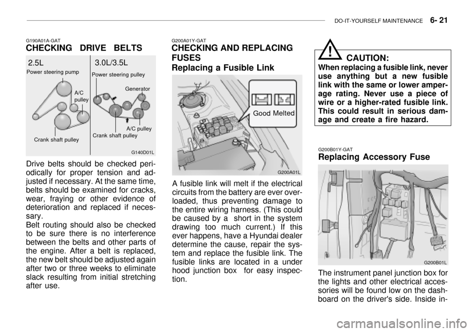
CHECKING DRIVE BELTS
Drive belts should be checked peri- odically for proper tension and ad- justed if necessary. At the same time, belts should be examined for cracks,wear, fraying or other evidence of deterioration and replaced if neces- sary. Belt routing should also be checked to be sure there is no interference between the belts and other parts ofthe engine. After a belt is replaced, the new belt should be adjusted again after two or three weeks to eliminateslack resulting from initial stretching after use. G140D01L
2.5L
3.0L/3.5L
Power steering pump
Crank shaft pulley A/C pulley
Crank shaft pulley
A/C pulley
Power steering pulley
Generator
G200A01Y-GAT
CHECKING AND REPLACING FUSES Replacing a Fusible Link
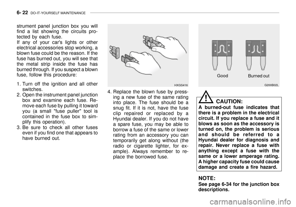
A fusible link will melt if the electrical circuits from the battery are ever over- loaded, thus preventing damage tothe entire wiring harness. (This could be caused by a short in the system drawing too much current.) If thisever happens, have a Hyundai dealer determine the cause, repair the sys- tem and replace the fusible link. Thefusible links are located in a under hood junction box for easy inspec- tion. G200A01L
Melted
Good
G200B01Y-GAT Replacing Accessory Fuse
G200B01L
The instrument panel junction box for
the lights and other electrical acces- sories will be found low on the dash- board on the driver's side. Inside in- CAUTION:
When replacing a fusible link, never use anything but a new fusiblelink with the same or lower amper- age rating. Never use a piece of wire or a higher-rated fusible link.This could result in serious dam- age and create a fire hazard.
!
Page 203 of 235
6- 22 DO-IT-YOURSELF MAINTENANCE
Good
G200B02L
Burned out
CAUTION:
A burned-out fuse indicates that
there is a problem in the electrical circuit. If you replace a fuse and it blows as soon as the accessory is turned on, the problem is seriousand should be referred to a Hyundai dealer for diagnosis and repair. Never replace a fuse withanything except a fuse with the same or a lower amperage rating. A higher capacity fuse could causedamage and create a fire hazard.
NOTE: See page 6-34 for the junction box
descriptions.
!
strument panel junction box you will find a list showing the circuits pro- tected by each fuse.
If any of your car's lights or other
electrical accessories stop working, ablown fuse could be the reason. If the fuse has burned out, you will see that the metal strip inside the fuse hasburned through. If you suspect a blown fuse, follow this procedure:
1. Turn off the ignition and all other switches.
2. Open the instrument panel junction box and examine each fuse. Re- move each fuse by pulling it toward you (a small "fuse puller" tool iscontained in the fuse box to sim- plify this operation).
3. Be sure to check all other fuses even if you find one that appears to have burned out.
HXGS416
4. Replace the blown fuse by press- ing a new fuse of the same rating into place. The fuse should be a snug fit. If it is not, have the fuseclip repaired or replaced by a Hyundai dealer. If you do not have a spare fuse, you may be able toborrow a fuse of the same or lower rating from an accessory you can temporarily get along without (theradio or cigarette lighter, for ex- ample). Always remember to re- place the borrowed fuse.
Page 206 of 235
DO-IT-YOURSELF MAINTENANCE 6- 25
Before performing aiming adjustment,
make sure of the following.
1. Keep all tires inflated to the correct
pressure.
2. Place the vehicle on level ground
and press the front bumper & rear bumper down several times. Place the vehicle at a distance of 3 m (118 in.) from the test wall.
3. See that the vehicle is unloaded (except for full levels of coolant,engine oil and fuel, and spare tire,jack, and tools). Have the driver or equivalent weight placed in driver's seat.
4. Clean the head light lenses and
turn on the headlights (low beam).
5. Open the hood.
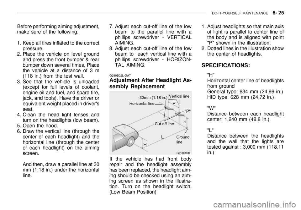
6. Draw the vertical line (through the center of each headlight) and the horizontal line (through the center of each headlight) on the aimingscreen. And then, draw a parallel line at 30 mm (1.18 in.) under the horizontal line.
G290B02L-GAT
Adjustment After Headlight As- sembly Replacement
G290B01L
LW
H
H Cut-off line
Ground line
If the vehicle has had front body
repair and the headlight assembly has been replaced, the headlight aim- ing should be checked using an aim-ing screen as shown in the illustra- tion. Turn on the headlight switch. (Low Beam Position)
"P"
Horizontal line
30mm (1.18 in.) Vertical line
7. Adjust each cut-off line of the low
beam to the parallel line with a phillips screwdriver - VERTICALAIMING.
8. Adjust each cut-off line of the low
beam to each vertical line with a phillips screwdriver - HORIZON- TAL AIMING. 1. Adjust headlights so that main axis
of light is parallel to center line ofthe body and is aligned with point"P" shown in the illustration.
2. Dotted lines in the illustration show the center of headlights.
SPECIFICATIONS: "H"Horizontal center line of headlightsfrom groundGeneral type: 634 mm (24.96 in.) HID type: 628 mm (24.72 in.) "W" Distance between each headlightcenter: 1,240 mm (48.8 in.) "L" Distance between the headlightsand the wall that the lights aretested against : 3,000 mm (118.11 in.)
Page 207 of 235
6- 26 DO-IT-YOURSELF MAINTENANCE
G260A01L-GAT
REPLACEMENT OF LIGHT BULBS
Before attempting to replace a light bulb, be sure the switch is turned tothe "OFF" position.The next paragraph shows how toreach the light bulbs so they may be changed. Be sure to replace the burned-out bulb with one of the samenumber and wattage rating.See page 6-33 for the wattage de-scriptions.
! CAUTION:
o Keep the lights out of contact with petroleum products, such as oil, gasoline, etc.
o Be sure to replace the LED type equipped bulbs with an assem-bly.Replacement instructions:
1. Allow the bulb to cool. Wear eye protection.
2. Open the engine hood.
3. Always grasp the bulb by its plastic base, avoid touching the glass. G270A03L
G270A02L-GAT
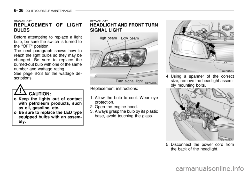
HEADLIGHT AND FRONT TURN SIGNAL LIGHT
High beam Low beam
Turn signal light
G270D01L
4. Using a spanner of the correct size, remove the headlight assem- bly mounting bolts.
G270D02L
5. Disconnect the power cord from the back of the headlight.
Page 214 of 235
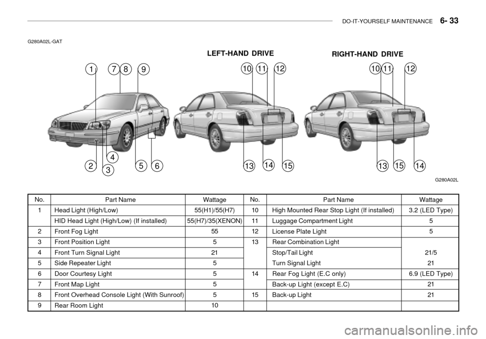
DO-IT-YOURSELF MAINTENANCE 6- 33
1456
4
Part Name
Head Light (High/Low) HID Head Light (High/Low) (If installed) Front Fog LightFront Position LightFront Turn Signal LightSide Repeater LightDoor Courtesy Light Front Map Light Front Overhead Console Light (With Sunroof)Rear Room Light Wattage
55(H1)/55(H7)
55(H7)/35(XENON) 555
21 5555
10
G280A02L-GAT
Wattage
3.2 (LED Type) 5 5
21/5 21
6.9 (LED Type) 2121
No.
1 2 345 6 789 No.
10111213 14 15 Part Name
High Mounted Rear Stop Light (If installed) Luggage Compartment Light License Plate LightRear Combination LightStop/Tail LightTurn Signal LightRear Fog Light (E.C only) Back-up Light (except E.C) Back-up Light
G280A02L
1978
231315
101112
LEFT-HAND DRIVE RIGHT-HAND DRIVE
151413
101112
Page 216 of 235

DO-IT-YOURSELF MAINTENANCE 6- 35
FUSE RATING
25A 20A10A15A10A10A10A15A10A10A15A 10A 10A 10A20A10A 15A 10A15A10A10A15A10A20A 10A 10A 10A 10A10A10A 10A 10A PROTECTED COMPONENTS
Power seat
Seat warmerEPS controls
ETS relay
(HID) Head lights, DRL controls, AQS sensor
Blower & A/C controls
Turn & Hazard controlsNot used
Cruise switch, Instrument cluster
Head light leveling switch, Rain sensor, IMS controls
Rain sensor relay, Wiper & Washer controls
Home link connector, Left (Right) vanity lights, Sunroof, Blower & A/C controls,Electronic chrome mirrorNot used
Audio
Front (Rear) cigarette lighter, Accessory socket
IMS controls, Driver door module, RheostatNot used
Rear for light relay
Stop lights, Left (Right) personal lights, Left (Right) rear door lights
Door warning & Ignition key illumination, Courtesy lightsInstrument clusterSRS controls
Automatic transaxle controls, Back-up light switch, Vehicle speed sensor
Fuel filler door & Trunk lid opener, Driver (Assister) door module
Multipurpose check connector, Audio, lmmobiilizer controls, Trip computers, Digital
clock, Blower & A/C controls, Instrument cluster
Left (Right) inside lights, (HID) Head lights, Fog light relay, Right HID turn signal light,Right rear combination light
Stop light failure relay
Immobilizer controls, TCS switch, Trip computers, Instrument cluster
ETACM, Hazard switch, Auto light sensor
Antenna, Blower & A/C controls, Left (Right) outside mirror motor & Folding motor
(HID) Head lights, Front (Rear) cigarette lighters, Left (Right) license lights, Left HID
Turn signal light, Left rear combination lightBurglar alarm relay, Transaxle range switch, Start relay, ETS controlsDESCRIPTION
P/SEAT
S/HTR EPSETS
H/LP
A/CON SW HAZARDSPARE
CRUISE IMS
WIPER
ETACS
SPARE AUDIO
C/LIGHTER MIRRORSPARE
RR FOG
STOP LP
ROOM LP
A/BAG IND A/BAGB/UP
T/LID
D/CLOCK
RH TAILSPARE
CLUSTER T/SIG
RR HTD IND
LH TAIL
START
G200D01L-GAT
Instrument Panel Junction Box
G200D01L