2003 HONDA CIVIC Synchro
[x] Cancel search: SynchroPage 20 of 1139

anuat I ransmcont'
ItemMeasutemenlOualificationStandard or NewServicc LimitNlainshaft 4th
and 5th gears
distance collar
LD.32.00-32.01 mm (1.2598 1.2602 in.)32.02 mm (1.261 in.)o.D.38.989 39.000 mm (1.5350 1.5354 in.)38.94 mm (1.533 in.)Length51.95 52.05 mm (2.045 2.049 in.)
B24.03 24.08 mm (0.946-0.947 in.)
MBS distanceLD.28.00 28.01mm (1.102 1.103 in.)28.02 mm (1.103 in.)Len9th23.95 24.05 mm (0.943 0.947 in.)Reverse idler
gear
t.D.20.016 20.043 mm (0.7880 0.7891 in.)20.90 mm (0.832 in.)Gear lo reverse gear shafi clearance0.036 0.08a mm (0.0014 0.0033 in.)0.16 mm {0.006 in.)Synchro ringBing to'gear clearanceRing pushed
against gear
0.70 1.49 mm (0.028 0 059 in )0.4 mm (0.016 4n.)
Triple coneOuter synchro ring-to synchro cone
clearance
Ring pushed
against qear
0.70 - '1.19 mm {0.028 0.047 in.)0.3 mm (0.012 in.)
Synchro cone-to-gear clearanceRing pushed
against gear
0.50 1.04 mm (0.020 0.041 in.)0.3 mm (0.012 in.)
Outer synchro ring-to-gear cone
clearance
Ring pushed
against gear
0.95 1.68 mm (0.037 0.066 in.)0.6 mm (0.024 in.)
Shift forkFinger thickness7.4 7.6 mm 10.29 0.30 in.)Fork to-synchro sleeve clearance0.35 0.65 mm (0.014 0.026 in.i1.0 mm (0.039 in.)Reverse shift
fork
Finger thinkness13.4 13.7 mm (0.527 0.539 in.)Fork-to-reverse idler gear clearance0.20 0.59 mm (0.007 0.024 in.)1.3 mm (0.051 in.)Shift armt.D.13.973 '14.000 mm (0.5501 0.5512 in.)Shift fork diameter at conlact area16.9 '17.0 mm (0.665 0.669 in.)Shift arm'to-shift lever clearance0.2 0.5 mm (0.008 0.020 in.)0.62 mm (0.024 in.)Select leverFinger width14.85 '14.95 mm (0.585 0.589 in.)Shift leverShaft -to-select lever clearance0.05 0.25 mm (0.002 0.010 in.)0.50 mm (0.020 in.)Groove {to select lever)15.00 15.10 mm {0.591 0.594 in.)
Shaft to shift arm clearance0.013 0.07 mm (0.0005 0.003 in.)0.1 mm {0.004 in.)Mfi
differential
carrier
Pinion shaft contact area l.D.18.010 18.028 mm (0.7091 0.7098 in.)Carrier-to-pinion shaft clearance0.027 0.057 mm (0.0011 0.0022 in.)0.1 mm (0.004 in.lDriveshaft contact area LD.28.025 28.045 mm (1.1033 1.1041 in.)Mfi
differential
pinion qear
Backlash0.05 0.15 mm {0.002 0.006 in.)
t.D.18.042 18.066 mm (0.7103 0.7113in.)Pinion gearto pinion shaft clearance0.059 0.095 mm (0.0023 0.0037 in.)0.15 mm (0.006 in.)80 mm shim80 mm shim to-bearing outer race
clearance in transmission housing
0 0.10 mm (0 0.0039 in.)Adjust
Standards and Service Limits
Manual Transmission and Differential?
LO
2-8
-
Page 103 of 1139

Cylinder Head
WEC Rocker Arms Test (cont'dl
'10. Loosen the valve on the regulator, and apply thespecified air pressure.
Specified air pressure:
290 kPa 13.0 kgt/cm', 42 psi)
NOTE: lf the synchronizing piston does not moveafter applying air pressure; move the primary orsecondary rocker arm up and down manually byrotating the crankshaft clockwise.
11. With the specified air pressure applied, move theintake primary rocker arm (A)forthe No, 1 cylinder.The primary rocker arm and secondary rocker arm(B) should move together.
lf the intake secondary rocker arm does not move,
remove the primary and secondary rocker arms asan assembly, and check that the pistons in theprimary and secondary rocker arms move
smoothly. lf any rocker arm needs replacing,
replace the primary and secondary rocker arms asan assembly, and test.
Remove the special tools.
Tighten the camshaft holder mounting bolts lo22N m 12.2 kgf.m, 16 lbf.ft).
Tighten the sealing boltto 20 N.m (2.0 kgf.m,
14 tbf.ft).
Installthe cylinder head cover (see page 6-41).
12.
13.
14.
t5.
6-8
VTG Actuator Inspection
'11. Remove the cylinder head cover (see page 6-22lr.
2. Remove the auto-tensioner (see page 6-19).
3. Loosen the rocker arm adjusting screws lsee step 2on page 6-26).
4. Remove the camshaft holder (see step 3 on page 6-
26t.
5. Remove the intake camshaft.
6, Check that the variable valve timing control (VTC)
actuator is locked by turning the VTC actuator
clockwise and counterclockwise. lf the VTC actuatoris not locked, replace the VTC actuator.
7. Seal the advance holes (A)and retard holes (B) in
the No. 1 camshaft journal with tape.
Punch a hole through the tape over one of theadvance holes.
Page 411 of 1139

Manual Transmission
SpecialTools
Transmission Fluid Inspection
and Reo1acement ...................-.
Back-Up Light Switch Test ..........
Transmission Removal
Transmission Installation ...........
Transmission Disassemblv ........
Reverse Shift Fork Clearance
lnsoection
Change Lever Clearance
lnsoection
Change Lever Assembly
Disassembly/Reassembly .......
Shift Forks Clearance
Inspection
Shift Forks
Disassembly/Reassembly .......
Mainshaft Assemblv
Clearance Inspection
Mainshaft Disassembly
Mainshaft lnsoection
Mainshaft Reassembly
Countershaft Assemblv
Clearance Inspection
Countershaft Disassembly .........
Countershaft Inspection .............
Countershaft Reassembly ..........
Synchro Sleeve and Hub
Inspection and Reassembly ....
Synchro Ring and Gear
Insoection ....... 13-39
Mainshaft Bearing and Oil Seal
Replacement ........................,... 13-41
Cou ntershaft Bearing
ReDlacement .. 13-42
Mainshaft Thrust Clearance
Adiustment ..... 13-43
Transmission Reassemblv ......... 13-46
Gearshift Mechanism
Replacement ............................ 13-51
M/T Differential
Comoonent Location Index ........ 13-52
Backlash Inspection ..................... 13-53
Final Driven Gear/Carrier
Replacement .. 13-53
Carrier Bearings Replacement ... 13-54
Oil Seal Replacement .................. 13-55
Differential Thrust Clearance
Adiustment ..... 13-56
13-2
| 5-J
tJ-5
13-4
I J-at
13-14
13- 19
13- 19
13-20
13-21
13-22
13-23't3-25
13-26
| 5-2.5
13-31
13-32
13-33
13-34
13-39
Page 431 of 1139

Shift Forks Glearance Inspection
NOTE: The synchro sleeve and synchro hub should be
replaced as a set.
1. Measu re the clearance between each shift fork (A)
and its matching synchro sleeve (B). lf the
clearance exceeds the service limit, go to step 2.
Standard: 0.35 0.65 mm {0.014 0.026in.1
Service Limit: 1.0 mm 10.039 in.l
A
l\4easure the thickness of the shift fork fingers.
. lf thethicknessof theshift forkfinger is not
within the standard, replace the shift fork with a
new one.. lf thethicknessof the shift forkfinger iswithin
the standard, replace the synchro sleeve with a
new one.
Standard: 7.4 7.6 mm (0.29-0.30 in.)
2.
3. Measure the clearance between the shift fork (A)
and the shift arm (B). lf the clearance exceeds the
service limit, go to slep 4.
Standard: 0.2-0.5 mm (0.007 0.020 in.)
Service Limit: 0.62 mm (0.024 in.)
Measure the width of the shift arm.
. lf thewidth of theshiftarm is notwithinthe
standard, replace the shift arm with a new one.. lf thewidth of the shift arm iswithinthe standard,
replace the shift fork and shift piece with a new
one.
Standard: 16.9-17.0 mm (0.665-0.669 in.)
4.
13-21
Page 433 of 1139

Mainshaft Assembly Clearance Inspection
NOTE: lf replacement is required, always replace the
synchro sleeve and hub as a set.
1. Support the bearing inner race with an appropriate
sized socket (A). and push down on the mainshaft(B).
Measure the clearance bet\iveen 2nd (C) and 3rd (D)
gears with a feeler gauge {E).
. lf the clearance is more than the service limit. go
to step 3.. lf the clearance is within the service limit, go to
step 4.
Standard:0.06 0.16 mm
{0.002 0.006 in.l
Service Limit: 0.25 mm (0.010 in.l
Measure the thickness of 3rd gear.
. lf thethickness of 3rd gearis lessthanthe service
limit, replace 3rd gearwith a new one.. lf thethickness of 3rd geariswithintheservice
limit, replace the 3rd/4th synchro hub with a new
one.
Standard: 23.92-23.97 mm(0.941 0.944 in.)
Service Limit: 23.80 mm (0.937 in.)
4. Measure the clearance between 4th gear (A) and
the distance collar (B) with a dial indicator (C).
. lf the clearance is more than the service limit, go
to step 5.. lf the clearance is within the service limit, go to
step 7.
Standard: 0.06 0.16 mnl(0.002 0.006 in.)
Service Limit: 0.25 mm {0.010 in.)
Measure distance O on the distance co[ar.
. lf distance't is notwithin the standard, replace
the distance collar with a new one.. lf distance e is within the standard, go to step 6.
Standard:24.03 24.08 mm
{0.946-0.9/u in.}
(cont'd)
13-23
Page 434 of 1139

Manual Transmission
Mainshaft Assembly Clearance Inspection (cont'd)
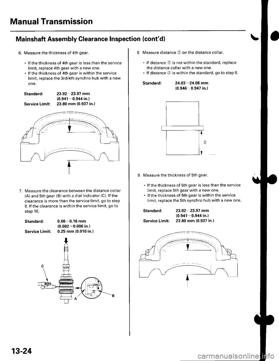
6. Measure the thlckness of 4th gear.
. lf thethickness of 4th gear is lessthantheservice
limit, replace 4th gear with a new one.. lf thethicknessof 4th geariswithin the service
limit. replace the 3rd/4th synchro hub with a new
one.
Standard: 23.92 23.97 mm
(0.941 0.944 in.)
Service Limit: 23.80 mm (0.937 in.)
7. l\4easure the clearance between the distance collar
(A) and sth gear (B) with a dial indicator (C). lfthe
clearance is more than the service limit. go to step
8. lf the clearance is with in the service limit, go to
steD 10.
Standard: 0.06 0.16 mm(0.002-0.006 in.)
Service Limit: 0.25 mm (0.010 in.)
13-24
Standard:
Standard:
Service Limit:
8. Measure distance O on the distance collar.
. lf distance O is notwithinthestandard, replace
the distance collar with a new one.' lf distanceO iswithinthe standard, gotostep9.
24.03 24.08 mm
(0.946 0.947 in.)
9. Measure the thickness of 5th gear.
. lf thethicknessof 5th gearis lessthantheservice
limit, replace 5th gear with a new one.. lf the thickness of sth gear iswithin the service
limit. replace the 5th synchro hub with a new one.
23-92 23.97 mm
10.941 0.944 in.l
23.80 mm (0.937 in.l
Page 435 of 1139

'10. Measure the thickness ofthe MBS distance collar.
. lf the thickness of MBS distance collar is less
than the standard, replace the MBS distance
collar with a new one.
Standard:23.95 24.05 mm
{0.9(3 0.947 in.)
E-f
Mainshaft Disassembly
1.Remove the angular ball bearing (A) and the
tapered cone ring using a commercially available
bearing separator {B) and a commercially available
bearing puller {C). Be sure the bearing separator is
under the tapered cone ring.
Support 5th gear (A) on steel blocks, and press the
mainshaft out of the sth synchro hub (B). Use of ajaw-type puller can damage the gear teeth.
(cont'd)
13-25
Page 436 of 1139

Manual Transmission
Mainshaft Disassembly (cont'dl
3. Supportthe 3rd gear (A) on steel blocks, and press
the mainshaft out of the 3rd/4th synchro hub (B).
Use of a jaw-type puller can damage the gear teeth.
13-26
Mainshaft Inspection
1. Inspect the gear surface and bearing surface for
wear and damage, then measure the mainshaft at
points A, B, C, D, and E. lf any part of the mainshaft
is less than the service limit, reDlace it with a new
o ne.
Standard:
A Ball bearing surface (transmission housing side):
27.987 28.000 mm (1.1019 1.1024in.)
B Distance collar surtace:
31.984 32.000 mm {1.2594 1.2598in.)
C Needle bearing surlace:
38.984-39.000 mm (1.53/t8 1.5354 in.)
D Ball bearing surface (clutch housing side):
27 .977 -27 .990 mm (1.1015 1.1020in.)
E Bushing surface:
20.80 20.85 mm (0.819 0.821 in.)
Service Limit;
A: 27.93 mm 11.100 in.l
B: 31.93 mm |.1.257 in.l
C: 38.93 mm 11.533 in.l
Di 27.92 mm {1.099 in.l
E: 20.75 mm 10.817 in.l
{