2003 HONDA CIVIC Filler
[x] Cancel search: FillerPage 193 of 1139

Radiator Cap Test
1. Remove the radiator cap {A), wet its seal with
engine coolant, then install it on the pressure tester(B) (commercially available).
Apply a pressure of 93 '123 kPa {0.95 1.25
kgf/cm', l4 18 psi).
Check for a drop in pressure.
lf the pressure drops, replace the cap.
3.
4.
Radiator Test
Wait untilthe engine is cool, then carefully remove
the radiator cap and fill the radiator with engine
coolant to the top of the filler neck.
Attach the pressure tester (A) (commercially
available) to the radiator.
1.
3.
4.
Apply a pressure ot 93 '123 kPa (0.95 1 .25
kgf/cm', '14 18 psi).
Inspect for engine coolant leaks and a drop in
pressu re.
Remove the tester, and reinstall the radiator cap.
10-3
Page 197 of 1139

1.
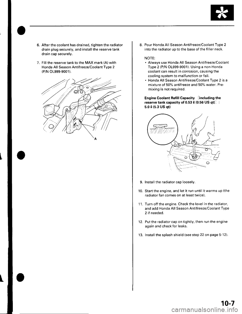
After the coolant has drained, tighten the radiator
drain plug securely. and installthe reserve tank
drain cap securely.
Fill the reserve tank to the MAX mark (A) with
Honda All Season Antifreeze/Coolant Tvpe 2
(P/N O1999-9001).
8. Pour Honda All Season Antifreeze/Coolant Type 2
into the radiator up to the base of the filler neck.
NOTE:. Always use Honda All Season Antifreeze/Coolant
Type 2 {P/N 01999-9001). Using a non-Honda
coolant can result in corrosion, causing the
cooling system to malfunction or fail.. Honda All Season Antifreeze/Coolant Type 2 is a
mixture of 50% antifreeze and 507o water. Pre-
mixing is not required.
Engine Coolant Refill Capacity including the
reserve tank capacity of 0.53 4 (0.56 US gtl :
5.0 0 (s.3 US qt)
Installthe radiator cap loosely.
Start the engine, and let it run until it warms up (the
radiator fan comes on at least twice).
Turn off the engine. Check the level in the radiator,
and add Honda All Season Antifreeze/Coolant Type
2 if needed.
Put the radiator cap on tightly, then run the engine
again and check for leaks.
lnstall the splash shield (see step 22 on page 5-12).
10.
11.
L
tJ.
10-7
Page 413 of 1139

Transmission Fluid Inspection and
Replacement
'1. Park the vehicle on level ground, and turn the
engine OFF.
2. Remove the oilfiller plug (A) and washer (B), check
the condition of the fluid, and make sure the fluid is
at the proper level (C).
lf the transmission fluid is diny, remove the drain
plug (D) and drain the fluid.
A44 N.m{4.5 kgt.m,33 rbr.ftl
Reinstall the drain plug with a new washer, and
refill the transmission fluid to the proper level.
Oil Capacity
1.5 0 (1.6 US (F) at tluid change
1.7 0 {1.8 US qt) at overhaul
Always use Honda Manual Transmission Fluid
(MTF). Using motor oil can cause stiffer shifting
and noise because it does not contain the proper
additives.
Reinstall the oil filler plug with a new washer.5.
13-3
Back-Up Light Switch Test
1. Disconnectthe back-up light switch (A) connector.
Check for continuity between the back up light
swilch 2P connector No. 1 and No.2 terminals.
There should be continuity when the shift lever is in
reverse.
lf necessary, replace the back-up light switch.
Apply liquid gasket (P/N 08718-0001), and install it
on the transmission housing.
2.
3.
Page 425 of 1139

o,. @\
'\b
e
P\B
z-W
-
€:
iq { "
Exploded View-Transmission Housing
@------
tt-P
"=-@
{i) 80 mm SHIM
0 8 x 14 mm DOWEL PIN
[A CHANGE LEVER ASSEMBLY
a0 6 mm FLANGE BOLT12 N m {1.2 kgf.m,9 lbf ft}
O DETENT BOLT22 N.m {2.2 kgf.m, 16lbf.ft)
O 12 mm waSHERReDlace.
(D SPRING
[I STEEL BALL(D TRANSMISSION HANGER B(9 CLUTCH LINE CLIP BRACKET
@
rai\€:/
o
f/
dd
\@
O=-rlF,z
O TRANSMISSION HOUSING
O 10 mm WASHERReplace.
@ 10 mm FLANGE BOLT44 N.m {4.5 kgf.m,33lbf.ft)
O 8 mm FLANGE BOLT27 N.m 12.8 kgf m,20lbl.ft)
.' TRANSMISSION HANGER A
O INTERLOCK BOLT39N m (4.0ksf.m,29lbf.ft)
O OIL GUIOE PLATE M
€.1 72 mm SHIM
.' OIL GUTTEB PLATE
,-1 _\(g/----------__-
"^\
\-/r*---------..-,
@) 20 mm WASHERReplace.
q,] FILLER PLUG44 N m {4.5 kgf.m,33 lbf.ft)
@ 40 x 56 x 8 mm OILSEALReplace.
qO 14 mm WASHERReplace.
q' DRAIN PLUG39 N.m (4.0 kgf.m,29 lbf.ftl
@ 32 mm SEALING CAP34 N m (3.5 kgf.m, 25 lbf.ft)
o
(cont'd)
13-15
Page 426 of 1139

Manual Transmission
Transmission Disassembly (cont'd)
NOTE: Place the clutch housing on two pieces of wood
thick enough to keep the mainshaft from hitting the
workbench.
1. Remove the detent bolts (A), springs, steel balls,
and back-up light switch (B).
Remove the vehicle speed sensor (VSS) (A) and
O-ring (B).
13-16
3, Remove the interlock bolt (A), the change lever
assembly (B), 8 x 14 mm dowel pins (C), andthe
clutch line clip bracket {D).
€
Remove the drain plug (A), filler plug (B), and
10 mm flange bolt (C).
Page 459 of 1139

16. Remove the dirt and oil from the shift iever cover
sealing surface. Apply liquid gasket (P/N 08718-
0001) to the sealing surface.
NOTE: lf 5 minutes have passed after applylng
liquid gasket. reapply it and assemble the housings.
Allow it to cure at least 20 minutes after assembly
before filling the transmission with oil.
- - -Liquid gasket
17. Installthe 8 x 14 mm dowel pins (A). clutch line clip
bracket (B), and change lever assembly (C).
12 N.m (1.2 kgf.m,9lbt ft)
18. Apply liquid gasket (Pi N 08718-0001) to the threads
of the interlock bolt (D), and install it on the
transmission housing.
6x1.0mm
19. Installthe drain plug (A), filler plug (B), and 10 mm
flange bolt (C) with new washers.
A39Nm(4.0 kgf m,33 tbl.ft)
20.
/..l-.=,'-Bg ^ 44N.m
@ Ut !?iJl'.'l,''
R\-: \
-.-t ?0, ,.ru ^44 N m {4.5 kgt m,33lbf.ft}
Installthe detent bolts (A), spring, and steel balls
with new washers.
{3.0 kgf.m.22lbf.ft)
Apply liquid gasket {P/N 08718-0001}to the threads
oithe back-up light switch (B), and install it in the
transmission housing.
(cont'd)
21.
13-49
Page 1135 of 1139

)
Orive BehInspecaron................ 4-26
Door PanelsRemoval/lnstallation -............................. 20-4
Door Sash TrimRep1acement......................................... 20 10
Door StrikersAdiustment ........................................... 20-13
Door Weatherst psBeplacement...........-............................. 20 1 1
EPS Conirol UnitRemoval/1nsta11ation ..................-......... 17-67
EPS Indicator CircuitTroubleshooting ................................... 17 -47
EPS MotorRemoval/lnstallation .-.......................... 17-49
EVAP CanisterRep1acement......................... ......... 11,189
EVAP Control Syst€mComponentLocation Index ..............'11-170
EVAP Two-Wey ValveTest ..........-.............-............................ 11 186
Evaporetor CoreRep1acement........................ . ... 21-42
Evaporator Tomperature SensorReplacement......................................... 21 -37Test..................................... ..........2137
EvaporrtoFHeater UnitReplacement........................................ 21 43
Exhaust ManifoldRemoval/1nsta11ation ................................ I 7
Exhaust Pipe8ep|acement............................................. 9-8
Front SpeakersRep|acement....................................... 22-102
Front SuspensionComponentLocation Index................... 18-3
Fueland EmissionsDescription ........................................... 11-12
Fuel Fill DoorAdjustment ..........-................................ 20 93
Fuel Fill Door OpenetBeplacement........................ . ............ 20.109
Fuel Fill Door Opener CableReplacement....................................... 20- lO7
Fuel FilterReplacement....................................... 1 1-152
Fuel Gauge Sending UnitTest ......................-.-..........-.................. 11'156
Fuel Injection Syslem (PGM"FIlComponent Location 1ndex................. 11-49
Fuel IniectorsRep1acemen1....................................... 1 1 1 1 l
Fuel Lines and HosesInspection .......................................... 1 1'146Removal ....................... . .. . .... 11-149Insta|1ation .......................................... 1 1 150
FuelPipe ProtectolReplacement....................................... 20-104
Fuel Pressure RegulatotReplacement....................................... 1 1-152
Fuel Pulsation DamperReplacemenl................................... 11 154
Fuel PumpReplacement,,,,,.,.,.,,,.,,,,,,,,,,,,.,.,.,,,..,.. 11-153
Fuel Pump CircuitTroubleshooting -.......-....................... 1 1-141
FuelSupply SystemComponent Location lndex .............. 11 140Adjustment................................... 11-144Test........-...-................. ... ............- 11-145
FuelTankBeplacemenl.............. . ..... .. 11 155
Fuel Tank Vapor ControlValveTest ......................-....... ... . . 11-187Replacement,,.,,...,.,,,.,.,,,,... .. .. 11 189
Fuses{See first page ofthis Index)
)
Rep|acement................. ..................... 4 26
Drive Belt Auto-tensionellnspection ............................................... 4 21Rep1acement.................................... ..4-28
Driver's PocketRemoval/lnstallation -........................... 20-60
Driver's TrayRemoval/lnstallation .........................-.- 20-65
DRL {Daytime Running LightslControl Unitlnput Test .................... ........ . . . ......22-16
DTCs(See first page olthis Index)
Dust and Pollen FillerReplacement......................................... 21-39
Dynamic Damper, DriveshaftsReplacement........................................... 16-8
ECT SensorReplacement.,.,,,.,.,,,,,,,,,,,,,,................ 1 1-1 14
El€ctrical Power Steering IEPS)Signal CircuitTroubleshooting ........ ... .. 11-135
EmblemsReplacement......................-................ 20-100
Engine AssemblyRemova1 .................................................... 5 2Installation ............._.................................. 5-9
Engine Block AssemblyComponent Location Inder ..................... 7.3
Engine Block, BareInspect|onRepair
Fan ControlsComponent Location Index................. 10'l 1Circuit Diagram .. ..... . .. . .................. 10 13
Fender Fairing, FrontReplacement...-................................... 20-103
Final Driven Gear. M/TReplacement.... . . ................................ 13-53
FrameRepair Chan............ ... ....................... 20 11 4
Frame StiffenelReplacement......-................................ 20- J'13
Front ConsoleRemoval/lnstallation ............................ 20 5lDisassembJy/Reassemb|y ................... 20 58
Front DoorsComponent Location Index................... 20-2Adiustment ........................................... 20.12
Front Driveshaft AssemblyInspeclion .................... ... ....16 3Remova1...................-...... ... .....16-3Disassembly ............................... .....165Resassemb|y ................................-......... 16-9Insta11arion ........................ ...... ............ l6 17
Front lmpact SensorsRep1acement............................ ...23 125
................7-15................1 11
)
Entry Light Control SystemComponent Location Index ...............-. 22-89Circuit Dia9ram .................................... 22 90
EPS ComponentsComponent Location 1ndex..........-...... 17-!7Description ........................ ...... ..17-24Circuit Diagram11 26(cont'd)