2003 HONDA CIVIC parking brake
[x] Cancel search: parking brakePage 908 of 1139

4. Make these input tests at the connector,
.lfanytestindicatesaproblem,findandcorrectthecause,thenrecheckthesystem.
. lf all the input tests prove OK, the control unit must be faulty. Replace it.
CavityWireTest conditionTest: Desired resultPossible cause if result is not obtained2R E D/BLUUnder all
conditions
Check for voltage to ground:
There should be battery voltage.
Blown No. 14 (40A) fuse in the
under-hood fuse/relay box
Blown No. 3 {10A)fuse in the
under-dash fuse/relay box
An open in the wire12YE L/RE Dlgnition switch
oN (r)Check for voltage to ground:
There should be battery voltage.
Blown No. l2 (7.5A)fuse in the
under-dash fuse/relay box
An open in the wire
BLKUnder all
conditions
Check for continuity to ground:
There should be continuitv.
. Poor ground {G50'1). An oDen in the wire7BLKUnder all
conditions
Check for continuity to ground:
There should be continuitv.
. Poor ground (G501)
' An open in the wire
10REDI/ELCombination
light switch ON/ =f\
Check for voltage to ground:
There should be battery voltage.
Blown No. 15 (15A) fuse in the
under-hood fuse/relay box
Faulty headlight relay 2
Faulty combination light switch
An open in the wire
1RED/B LUCombination
light switch ON
{iD), and
dimmer switch
in HIGH
Connect a jumper wire between
No.3 and No. 1 terminals.
Both headlights (HIGH) and
h igh beam indicator light
should come on.
Blown bulb
Faulty low beam cut relay
Faulty combination light switch
Poor ground (G50'l )
An open in the wire'11
3
RED/BLK
GRN/BLK
Combination
light switch ON(iD), and
dimmer switch
in HIGH
Com bination
light switch ON(iD), and
dimmer switch
in HIGH
Connect a jumper wire between
No. 5 and No. 11 terminals.
Right headlight (HIGH) should
come on.
Check for continulty to ground
There should be continuity.
. Blown bulb. Faulty combination light switch. Poor ground (G 50'1 ). An open in the wire
. Faulty combination light switch. Poor grou nd {G501). An open in the wire
5
6GRN/ORNParking brake
lever oulled
Check for continuity to ground:
There should be continuitv.
Faulty parking brake switch
An open in the wire
8BLU/REDCombination
light switch OFF
Check for voltage to ground:
There should be battery voltage.
Faulty headlight relays
Short to ground
An ooen in the wire
WHT/BLUlgnition switch
oN 0r)
Attach to ground:
The DRL indicator light should
come on.
. Blown No. 10 (7.5A) fuse in the
under-dash fuse/relay box. Faulty DRL indicator. An ooen in the wire
t5G RN/REDlgnition switch
oN (||)Attach to ground:
The brake system light should
come on.
Faulty brake system indicator
An open in the wire
22-77
Page 997 of 1139

lmmobilizer System
Troubleshooting (cont'dl
8. Check for voltage betvveen the immobilizer control
unit-receiver 7P connector No. 6 terminal and No. 1
rermlnat.
ls thete battery voltage?
YES Go to step 12.
NO Check for these problems,
. Open on the BRNI/EL wire.l. Faulty ECM.I
9. Remove the driver's dashboard lower cover (see
page 20-59).
10. Remove the steering column lower cover (see page
17-9).
11. Disconnect the 7P connector (A) from the
immobilizer control unit-receiver (B).
22-166
-
Check for continuity between the immobilizer
control unit-receiver 7P connector No. 2 terminal
and ECM terminal E27.
ls there continuity?
YES-Go to step 13.
NO- Repair the open in the RED/BLU wire.I
Reconnect the 7P connector to the immobilizer
control unit-receiver.
Check for voltage between the immobilizer control
unit-receiver 7P connector No. 4 terminal and body
ground with the parking brake lever pulled, then
released.
ls there 1 V or less, then 5 V or more?
YES Replace the immobilizer control unit-receiver.
After replacing the immobillzer control unit-
receiver, rewrite the unit with a Honda PGM
Tester.l
NO Check for these problems:
. Faulty parking brake switch or a poor body
ground of the parking brake switch.l. Repair short or open in the GRN/ORN wire. I
13.
14.
{
Page 1007 of 1139

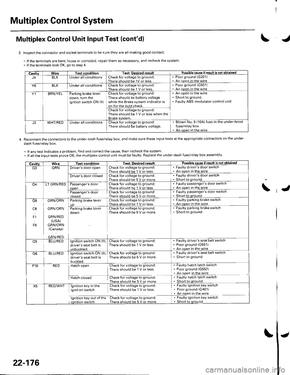
Multiplex Control System
Multiplex Control Unit lnput Test (cont'd)
3. Inspect the connector and socket terminals to be sure they are all making good contact
.lftheterminalsarebent,looseorcorroded,repairthemasnecessary,andrecheckthesystem. llthe terminals look OK, go to step 4.
4. Reconnectthe connectorstothe under dash fuserelay box, and make surethese inputtests atthe appropriate connectors on lhe under-
dash fuse/relav box.
. lf any test indicates a problem, {ind and correct the cause, then recheck the system. lf allthe input tests prove OK, the multiplex control unit must be faulty. Replace the under_dash fuse/relay box assembly
CavitvWireTest conditionTest: Desired .esult r Possible cause if resullE qS!q!!e!!ed
J4BLK[J nder all conditionsCheck {or voltage 1o ground:Therc sholl.l he 1V or lessPoor ground (G20'l)An ooen in the wire
Y6BLKlJnder all conditionsCheck for voltage to ground:There should bc 1 V or less.Poor ground 1G501)An ooen in the wire
Y1BFNryELParking brake leverdown, turn theigntion switch ON (ll)
Check for voltage to ground:There should be battery voltagewhile the Brake system indicator ison forthe buld check.
An open in the wireShortto groundFaulty ABS modulatorcontrol unit
Check for voltage to ground:There should be 1V or less when the
J2WHT/REDUnder allconditionsCheck for voltage to groundiThere should be baftery voltage.Blown No.9 (10A)fuse in the under'hoodfuse/relay boxAn oncn in rhc wire
CavitvTest conditionTesi: Oesired resultPossible cause ifresult is notobtained
o3GRNDriver's door openCheck for voltage to ground:There should be 1 V or less-Faulty driver's door switchAn ooen in the wire
Driver's door closedCheck for voltage to ground:There should be 5 V or more.Faulty driver's door switchShort to qround
O4LT GRN/REDPassenger's doorCheck .for voltage 10 ground:There should be 1 V or less.Faulty passenger's door switchAn ooen inthewire
Passenger's doorCheck for voltage to ground:There should be 5 V or more.Faulty passenger's door switchShort to oround
osI]l.l
4.,
F1
F8
GRN/ORN
GRN/ORN
GRN/RED(USA)GRN/ORN(Canada)
Parking brake leverCheck for voltage to groLrnd:There shorl.l be 1 V or less.Faulty parking brake switch. An ooen in thewireCheck for voltage to ground:There should be 5 V or more.
. Faulty parking brake switchShortto ground
o5BLU/REDlgnition switch ON (ll),
driver's seat belt isCheck for voltage to ground:There should be 1V or less.Faulty driver's seat belt switchPoorground (G551)An oDen in the wire
Q6BLU/REDlgnition switch ON (ll)
driver's seat belt isbuckled.
Check {or voltage to ground:There should be 6 V or more.Faulty driver's seat belt switchShortto ground
P18RED
H",=
Check for voltage to ground:There sho0ld be 1V or less-
f -9*:li:'^:**:':s*:*
Faulty hatch latch swrtchPoor ground (G552)An open in the wireFaulty hatch latch switch
X5lgnirion key in the Check for voliage to gtound:ignit on switch Thpre should be I V or lcss
lgnrtron kev our o{ the Check for vollage to ground:
. Faulty ignition key switch. Poor ground (G401). An open in the wire
I : [11y.'::i':::1"' **6
\
22-176
Page 1137 of 1139

)
Low Fuel lndicatorTest.....................11-158Moonroof Drain Channel SliderReplacement......................................... 20'44
Moonroof FrameRep1acement,,,,,,,,,,.,.,.,.,.,.,.,,,,,,............ 20 42
MoonroolGlassAdiustment ........................................... 20-37Rep1acement......................................... 20 37
Moonroot Limit SwitchAdjustment ........................................-.- 20 46Test ...................................................... 22 113
Moonrool MotorReplacement....-.................................... 2D-41
Oil Pressure SwitchTest ................-.-........-................................ 8-4Replacement.........-................................. 8-16
Oil Pump, EngineOverhau1 ................................................... 8-8
Oil, EngineReplacement...-................-.-...................... 8-5
OPDS UnitReplacement....................................... 23- 124
Outside Mirror HoldersBeplacement......................................... 20-15
Outside Power Mirror ActuatorsTest ...................................................... 22-117Bepf acement..-.................................... 22-1 14
Outside Power Mirror SwitchTest ..-................................................... 22-111
Outsid€ Power MirrorsReplacement............................ ... .. . . . 20-15Component Location lndex .............. 22- 114Circuit Diagram .................................. 22-115Test -..................................................... 22-116
Lower ArmsRemoval/1nsta11ation............................ 18 19
Lubrication SystemComponent Location Index..................... 8-3Test............................................................ 8 4
M
M/TAssemblyRemoval.......... 13-4 Test...................... 22-1 12lnstallation............. 13-8
.........21,35
Disassembly ......................................... 13-14Resassembly .. ... ................. 13-46
M/TChange Leverlnspection ............................................. 13-19Disassembly 8eassemb1y ................... 13-20
M/T Countershaft AssemblyInspection ....................................... 13 31, 33Disassemb1y ......................................... 13-32Resassemb|y ........................................ 13-34
M/T DifferentialComponentLocation Index................. 13-52Adiuslment ........................................... 13-56
M/T Maifthaft Assembly1nspection ... ................................... 13-23, 26Disassembly ......................................... 13 25Resassembly ........................................ 13 28Adjustment ........................................... 13-43
M/T Reverse Shift ForkInspection .................... ........................ l3 19
M/T Shift LevelReplacement......................................... 13-51
Mainshaft BearingsReplacement....,.................................... 13 41
MairtenancelSee section 3)
MILHow to Informatron ............................. 1 1.46
MIL CircuitTroubleshooting .......... .- . . . . ......... 11 97
MirrorsComponentLocation Index................. 20'14
Mode Control MotorReplacement
Moonrool SunshadeRep1acement....................... . . ............. 20 40
Moonroof SwitchTesVRep1acement .............................. 22- l 12
Mooniool Wind Def lectorReplacement.......................-................. 20-38
Moonroof/SunroofComponent Location Index ... 20-35, 22-108Test ........................................................ 20-48Cf rcuit Diagram .................................. 22- 109
MTFInspection/Rep1acement. .......... ........... 13-3
Muhiplex Control SystemComponentLocation lndex ..............22 168Circuit Diagram .................................. 22-1690escription ......................................... 22-17 1Troubleshooting ................................ 22-17 2
Muliiplex Control Unit, Under-dashInput TestEntry Light Control Sysiem ............. 22-92Keyless Entry/Security AlarmSystern .-....................................... 22-155MultiplexControl System .............22 115Wiper/Washer................................. 22'1 41
NoiseTest,,Reduction Condenser
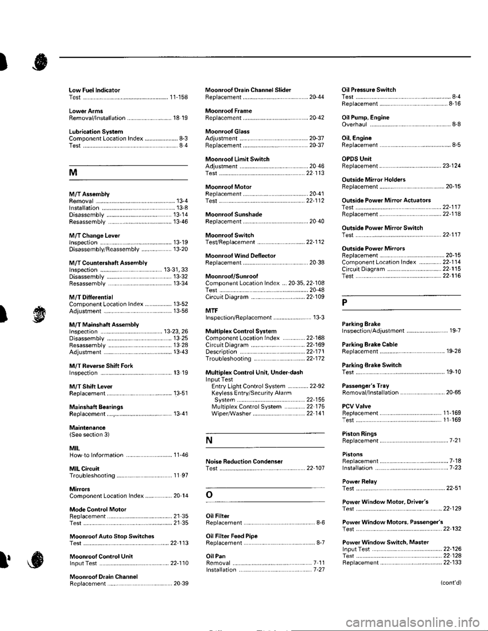
Parking ErakeInspection Adjustment ........... .............. 19-7
Parking Brake CableRep1acement......................................... 19-26
Parking Erake Switch
P
l
Test ...................... 19-10
Test............................... . ...........2135
Moonroof Auto Stop SwitchosTest ...................................................... 22'113
Moon.oot Control Unillnput Test ............................................ 22-110
Moonroof Drein ChannelBeplacement ... . ....... ......................... 20 39
Oil Filte]Replacement............................................. 8-6
Oil Filter Feed PipeReplacement............... . ..-,...,.,,,,,,,,8-7
Oil PanRemoval .............,.,,,,,,,,,,,,.,.,,,.........-....... 7 1 1lnstallation .............................................. 7 -27
Passenger's TraVRemoval/lnstallation ............................ 20-65
PCV ValveBeplacement....................................... 1 1'169Test........................................... l1 169
Piston Rings8ep1acement................................-.-...-.- 7-21
PistonsReplacement...................-....................... 7-181nsta|1ation ...................................... ...1-23
Power R€layTest ...............-.-...................................... 22-51
Power Window Motor, Driver'stesl.....,,,, .,.,,,............
Power Window Motors, Passenger's
Power Window Switch, Masterlnput Test ..........-.........-....................... 22-126Tesr ....... . ............................................ 22 124Replacement....................................... 22-133
N
..............22 101
o
l' ,e
(cont'd)