2003 HONDA CIVIC oil pump
[x] Cancel search: oil pumpPage 358 of 1139

4. Align the quick-connect fittings with the line (A).
and align the retainer (B) locking pawls with the
connector {C) grooves. Then press the quick-
connect fittings onto the line until both retainer
pawls lock with a clicking sound.
NOTE; lf it is hard to connect, put a small amount of
new engine oil on the line end.
Connection with new retainer:
Reconnection to existing retainer:
5. lvlake sure the connection is secure and that the
pawls are firmly locked into place; check visually
and by pulling the connector.
6. Reconnectthe negative cable to the battery, and
turn the ignition switch ON (ll). The fuel pump will
run for about 2 seconds, and fuel pressure will rise
Repeat 2 or 3 times, and check that there are no
fuel leaks.
11-151
Page 635 of 1139

t
Wheel Sensors
The wheel sensors are the magnetic contactless type. As the gear pulser teeth rotate past the wheel sensor's magnetic
coil, AC current is generated. The AC frequency changes in accordance with the wheel speed. The ABS control unit
detects the wheel sensor signal frequency and thereby detects the wheel speed.
!t LOW SPEED
Wheel Speed and Modulator Control
8E!EEETqE VEJ!q!ESPEEq
5
PRESSURE
OUTLETVALVE 9p
OFF
INLETVALVE oN
OFF
MoroR I-,. ltlOFF
When the wheel speed drops sharply below the vehicle speed, the inlet valve closes and il necessary, the outlet valve
opens momentarily to reduce the caliper fluid pressure. The pump motor starts at this time. As the wheel speed is
restored, and the outlet valve closes, the inlet valve opens momentarily to increase the caliper fluid pressure.
GEAR PULSERWHEEL S€NSOR.r HIGX SPEED
19-41
Page 878 of 1139

Under-dash Fuse/Relay Box
Fuse
Number
AmpsWire ColorComponent(s) or Circuit(s) Protected
115ABLKA/VHTlgnition coils
2204WHT/REDAirlfuel ratio sensor, ECM
310ARED/BLUDaytime running Iights control unit {Canada)10ABLI(ORNAir/fuel ratio sensor relay, Alternator, CMP sensor, Cruise control main
switch, Cruise control unit. ELD unit, Evaporative emission (EVAP) bypass
solenoid valve, Evaporative emission (EVAP)canister purge valve,
Evaporative emission (EVAP) canister vent shut valve, Secondary H02S,
Vehicle speed sensor
5Not used
67.5AYEUGRNMoonroof control unit, Moonroof open and close relay, Power window
relaV
7204GRNMoonroof motor
I7.5AYEUREDAudio unit
910AGRNOPDS unit, Rear window wiper motor, Rear window washer motor, Rear
window wiper intermittent control unit
107.54YELBack-up lights, Cruise indicator light, EPS control unit, Gauge assembly,
Keyless receiver unit, Multiplex control unit, Security control unit
connector (optional)
117.5ABLIVORNABS modulator-control unit
127.5AYEUREDDaytime runnino liohts control unit (Canada)
1310APNKSRS unit't410ABLK/YE LA,,/C compressor clutch relay, Blower motor relay, Condenser fan relay,
Heater control panel, Power mirror actuator, Power mirror defogger(Canada), Radiator fan relay, Rear window defogger relay, Recirculation
control motor1ENot used
loNot used
1715AYE L/B LKECM, Fuel pump
B LK/YE L>H> Unrr
1815AYEUGRNAccessory power socket
197.5AYEUBLKTurn siqnal/hazard relav, Turn siqnal liohts
2030AGRN/BLKMultiplex control unit, Windshield washer motor. Windshield wioer motor21Not used
22204GRN/BLKPassenqer's window motor
2320A.G R N,A/VHTDriver's window motor
24Not used
25Not used
__^:Hr tl_l
f at-t
at I
r^,rl fl
!!;r -
!339,i;s!!sf Fnf : |rnITf
22-47
Page 879 of 1139

Ground Distribution
Ground to Components Index
GroundComponent or circuit qrounded
Batterv, Transmission housinq
E ngine
G 101ECM (PG is BLK; LG is BRN/YEL)
BLK: IAC valve, lgnition coils, Vehicle speed sensor, VTEC solenoid valve
BRNA/EL: Camshaft oosition (CMP) sensor. CKP sensor, TDC sensor. VTEC oil pressure switch
G 15'�]EPS control unit
G201ELD unit. Multiplex control inspection connector, Multiplex control unit, Power window relay, Rear
window washer motor, Right front parking light, Right front side marker light, Right front turn signal
light, Turn signal/hazard relay, Washer fluid level sensor (Canada) , Windshield washer motor,
Windshield wiDer motor
G202ABS modulator-control unit
G301
G401
Blower motor relay, Brake fluid level switch, Condensor fan motor, Cruise control actuator, Left front
parking light, Left front side marker light, Left front turn signal light, Radiator fan motor, Radiator fan
swrtcn
Combination liqht switch, lqnitlon kev srvitch, Wiper/wasfrer sr,virch
G402Left and riqht airbaq sensors, SRS unit
G 451Data link connector (DLC)
G501Clutch interlock switchm Clutch pedal position switch (for cruise control), Cruise control main switch,
Cruise control unit, Daytime running lights control unit (Canada), Driver's door lock knob switch,
Driver's door lock switch, Driver's power window motor, Heater control panel, Left power mirror
defogger (Canada), left side turn signal light, Moonroof control unit, Monroof open and close relays,
Moonroof position sensor '1, Moonroof seitch, Power mirror switch, Power transistor, Power window
master switch. SDotliqhts
G502Accessory power socket, Gauge assembly, Keyless receiver unit, lvlultiplex control unit, Right power
mirror defogger {Canada)
G503Audio unit
G551Driver's seat belt switch, Fuel gauge sending unit, Fuel pump, Memory erase signal (IMES) connector,
OPDS unit. Rioht seat belt switch
G552High mount brake light, License plate lights, Rear window defogger, Rear window defogger noise
condenser. Rear window wioer motor, Hatch latch switch
Back-up lights, Brake lights, Rear side marker lights, Rear turn signal lights, Rear window wiper noise
condenser, Rear window wiper intermittent control unit, Taillights
22-48
Page 1137 of 1139

)
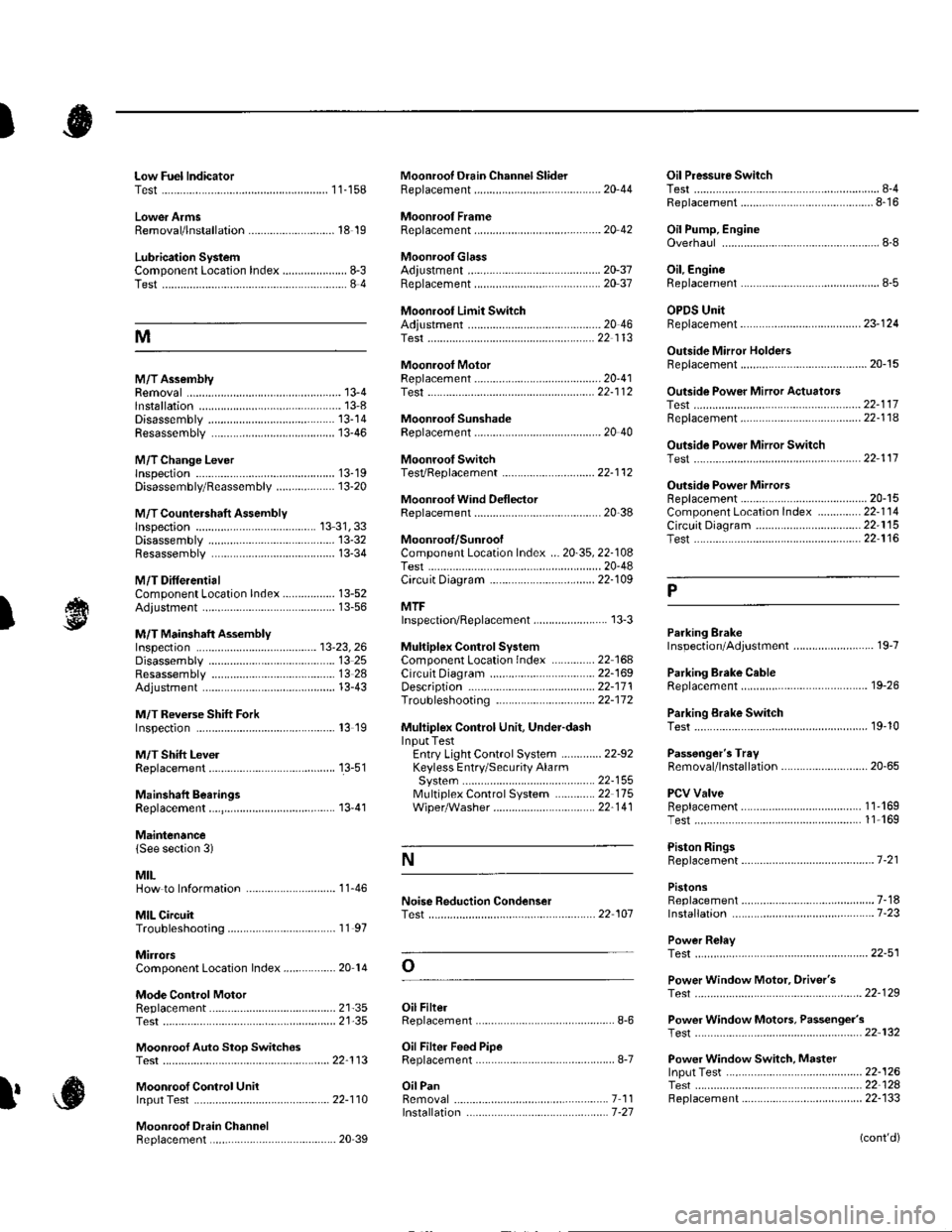
Low Fuel lndicatorTest.....................11-158Moonroof Drain Channel SliderReplacement......................................... 20'44
Moonroof FrameRep1acement,,,,,,,,,,.,.,.,.,.,.,.,,,,,,............ 20 42
MoonroolGlassAdiustment ........................................... 20-37Rep1acement......................................... 20 37
Moonroot Limit SwitchAdjustment ........................................-.- 20 46Test ...................................................... 22 113
Moonrool MotorReplacement....-.................................... 2D-41
Oil Pressure SwitchTest ................-.-........-................................ 8-4Replacement.........-................................. 8-16
Oil Pump, EngineOverhau1 ................................................... 8-8
Oil, EngineReplacement...-................-.-...................... 8-5
OPDS UnitReplacement....................................... 23- 124
Outside Mirror HoldersBeplacement......................................... 20-15
Outside Power Mirror ActuatorsTest ...................................................... 22-117Bepf acement..-.................................... 22-1 14
Outside Power Mirror SwitchTest ..-................................................... 22-111
Outsid€ Power MirrorsReplacement............................ ... .. . . . 20-15Component Location lndex .............. 22- 114Circuit Diagram .................................. 22-115Test -..................................................... 22-116
Lower ArmsRemoval/1nsta11ation............................ 18 19
Lubrication SystemComponent Location Index..................... 8-3Test............................................................ 8 4
M
M/TAssemblyRemoval.......... 13-4 Test...................... 22-1 12lnstallation............. 13-8
.........21,35
Disassembly ......................................... 13-14Resassembly .. ... ................. 13-46
M/TChange Leverlnspection ............................................. 13-19Disassembly 8eassemb1y ................... 13-20
M/T Countershaft AssemblyInspection ....................................... 13 31, 33Disassemb1y ......................................... 13-32Resassemb|y ........................................ 13-34
M/T DifferentialComponentLocation Index................. 13-52Adiuslment ........................................... 13-56
M/T Maifthaft Assembly1nspection ... ................................... 13-23, 26Disassembly ......................................... 13 25Resassembly ........................................ 13 28Adjustment ........................................... 13-43
M/T Reverse Shift ForkInspection .................... ........................ l3 19
M/T Shift LevelReplacement......................................... 13-51
Mainshaft BearingsReplacement....,.................................... 13 41
MairtenancelSee section 3)
MILHow to Informatron ............................. 1 1.46
MIL CircuitTroubleshooting .......... .- . . . . ......... 11 97
MirrorsComponentLocation Index................. 20'14
Mode Control MotorReplacement
Moonrool SunshadeRep1acement....................... . . ............. 20 40
Moonroof SwitchTesVRep1acement .............................. 22- l 12
Mooniool Wind Def lectorReplacement.......................-................. 20-38
Moonroof/SunroofComponent Location Index ... 20-35, 22-108Test ........................................................ 20-48Cf rcuit Diagram .................................. 22- 109
MTFInspection/Rep1acement. .......... ........... 13-3
Muhiplex Control SystemComponentLocation lndex ..............22 168Circuit Diagram .................................. 22-1690escription ......................................... 22-17 1Troubleshooting ................................ 22-17 2
Muliiplex Control Unit, Under-dashInput TestEntry Light Control Sysiem ............. 22-92Keyless Entry/Security AlarmSystern .-....................................... 22-155MultiplexControl System .............22 115Wiper/Washer................................. 22'1 41
NoiseTest,,Reduction Condenser
Parking ErakeInspection Adjustment ........... .............. 19-7
Parking Brake CableRep1acement......................................... 19-26
Parking Erake Switch
P
l
Test ...................... 19-10
Test............................... . ...........2135
Moonroof Auto Stop SwitchosTest ...................................................... 22'113
Moon.oot Control Unillnput Test ............................................ 22-110
Moonroof Drein ChannelBeplacement ... . ....... ......................... 20 39
Oil Filte]Replacement............................................. 8-6
Oil Filter Feed PipeReplacement............... . ..-,...,.,,,,,,,,8-7
Oil PanRemoval .............,.,,,,,,,,,,,,.,.,,,.........-....... 7 1 1lnstallation .............................................. 7 -27
Passenger's TraVRemoval/lnstallation ............................ 20-65
PCV ValveBeplacement....................................... 1 1'169Test........................................... l1 169
Piston Rings8ep1acement................................-.-...-.- 7-21
PistonsReplacement...................-....................... 7-181nsta|1ation ...................................... ...1-23
Power R€layTest ...............-.-...................................... 22-51
Power Window Motor, Driver'stesl.....,,,, .,.,,,............
Power Window Motors, Passenger's
Power Window Switch, Masterlnput Test ..........-.........-....................... 22-126Tesr ....... . ............................................ 22 124Replacement....................................... 22-133
N
..............22 101
o
l' ,e
(cont'd)
Page 1139 of 1139

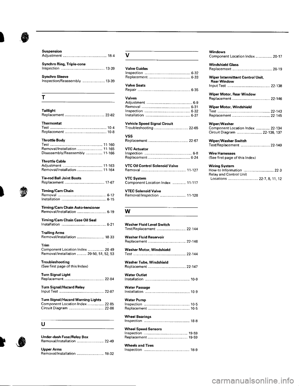
SuspensionAdjustment................-............................184 VComponent Location Index................. 20-17
Windshield GlessReplacement............-..............-............. 20 19
Synchro Ring, Triple-coneInspection...............-..........................1339 ValveGuides
Synchro SleeveInspectaon/Reassemb1y ....................... 13 39
Inspection ............-.-................................ 6 32Beplacement ..........-................................ 6 33 Wiper Intermittent Control Unit,Rear WindowInput Test
T
Valve SeatsRepair ...................................................... 6 35.....22-134
WiDer Motor, Rear WindowRep1acement....................................... 22-1 46Adjustment .-.-.......Removal ...-...-......................................-... 6-31 WiDer Motor, windshield6-9
.....6-32 Test.......-..........-.....-.............................22-143Taillight
ThermostaiTest ........................
Inspec!on
Vehicle Speed Signal Circuit
VTC System
Wiper/WasheI
Wi.ing System
10 4 Troubleshooting .....-... ..........................22-65 Component Location In dex ..............22-134Replacement.....-...-....... ...................... 10 IvssThrottle BodyTest ..................Removal/lnstallation .. . . . . . .. ... 11-'165 VTC ActuatorDisassembly/Feassemb|y................-11-166 Inspection
Circuit Diagram .......................... 22-136, 131
Replacement -.............. ............ .............22 61 Wiper/Washor SwitchTesVReplacement .............................. 22-1 40
.................68 WireHarnesses
11-160
Replacement ........................................... 6 24 (Seefirstpageofthislndex)Throttle CableAdjustment ...... ...-.................... 11163 VTC Oil ConlrolSolenoid ValveRemoval/1nsta11ation..........................11164 Removal....-...-... |1-127 HowtoIn{ormation ...............................223Belay and Control UnitLocations .-....-.............. -.-.-....- 22-7, 4, 1 1, 12Beplacement.........-............................... 1767 ComponentLocationlndex.............. 11-117Tie-rod Ball Joint Boots
lnstallation
Replacement
Turn Signal/Hazard Relay
tsTiming/Cam ChainVTEC Solenoid Valve...612 Femoval/lnspection....-......................11-128................ 6 15
Timing/Cam Chain Auto-tensionelRemoval/1nsta11ation..............................6-19 W
Troubleshooting{See first page ot this Index)
Turn Signal Light
Timing/Cam Chain CaseOil SealInstallation......................-......................6,21 Washer Fluid Level SwitchTesVReplacement .............................. 22 1 44Trailing ArmsRemoval/lnstallation .............. . . . . ..... 18 33 Washer Fluid ReservoirReplacement ....................................... 22-1 46tnmComponent Location lndex ................- 20 49 Washer Motor, WindshieldRemoval/lnstallation ..-.......20 50,51,52,53 Test -..............-.............. ........................22 144
Washer Tube, WindshieldReplacement......-...-............................ 22 1 47
W.ter Outlet.........22 A4 Installation ..................-........................... '10-9
InputTest........22-87 lnstallation................ 10IWeter Passage
Wheels andTires
Turn Signal/Hazard Warning Lights Water PumpComponent Location In dex .................22 85 Inspection ........................... .. . . . ....... 10 5Circu it Diagram ................-................... 22-86 Replacement .-......................................... 10 5
U
WheelBearingsInspec|ion ....................................... ....... 18 8
Wheel Speed SensorsInspection ..-..,.,.,,.,,,,,.,.,,,...................... 19-59Replac€ment ........-....... . . . . . . .. -.... 19-59UndeFdash Fuse/R€lay BoxRemoval/lnstaf lation ............................ 22-49
Upper ArmsRemoval/|nsta11ation................. ... 18-32
],sInspect|on