2003 HONDA CIVIC k2 terminal
[x] Cancel search: k2 terminalPage 1047 of 1139
SRS
16.
DTC Troubleshooting (cont'd)
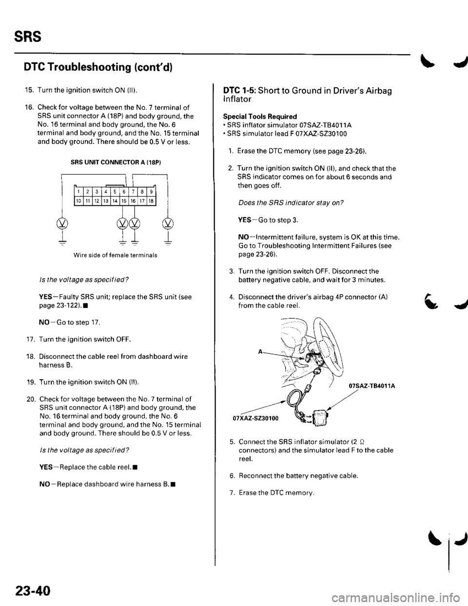
Turn the ignition switch ON {ll).
Check for voltage between the No. 7 terminal of
SRS unit connector A (18P) and body ground, the
No. 16 terminal and body ground, the No.6
terminal and body ground, and the No. 15 terminal
and body ground. There should be 0.5 V or less.
SRS UNIT CONNECTOR A {18P)
11.
Wire side ol lemale terminals
Is the voltage as specilied?
YES-Faulty SRS uniU replace the SRS unit (see
page 23-122) .a
NO Go to step 17.
Turn the ignition switch OFF.
Disconnect the cable reel from dashboard wire
harness B.
Turn the ignition switch ON (ll).
Check for voltage between the No. 7 terminal of
SRS unit connector A (18P) and body ground, the
No. 16 terminal and body ground, the No. 6
terminal and body ground, and the No. 15 terminal
and body ground. There should be 0.5 V or less.
ls the voltage as specitied?
YES Replace the cable reel.l
NO-Replace dashboard wire harness B.l
18.
19.
20.
23-40
1.
IJ
L
DTC 1-5: Short to Ground in Driver's Airbag
lnflator
Special Tools Required. SRS inflator simulator 07SM-TB4011A. SRS simulator lead F 07XM-S230100
1. Erase the DTC memory (see page 23-26).
2. Turn the ignition switch ON (ll), and checkthatthe
SRS indicator comes on for about 6 seconds and
then goes oIf.
Does the SBS indicator stay on?
YES Go to step 3.
NO-lntermittent failure, system is OK at this time.
Go to Troubleshooting Intermittent Failures (see
page 23-26).
3. Turn the ignition switch OFF. Disconnect the
battery negative cable, and wait for 3 minutes.
4. Disconnect the driver's airbag 4P connector (A)
from the cable reel.
07sAz-T84011A
07xaz-s230100
Connect the SRS inflator simulator (2 0
connectors) and the simulator lead F to the cable
reet.
Reconnect the battery negative cable.
Erase the DTC memory.
a
Page 1048 of 1139
8. Read the DTC.
ls DTC 1-5 indicated?
YES-Go to step 9.
NO Short to ground in the driver's airbag inflator;
replace the driver's airbag (see page 23-1 13).I
9. Turn the ignition switch OFF. Disconnect the
battery negative cable, and wait for 3 minutes.
'10. Disconnectthe front passenger's airbag 4P
connector from dashboard wire harness B (see step
2 on page 23-21) .
11. Disconnect both seat belt tensioner 2P connectors
from the floor wire harness (see step 5 on page 23-
22t.
12. Disconnect SRS unit connector A (18P) fromthe
SRS unit (see step 7 on page 23-22],.
13. Disconnectthe specialtoolfrom the cable reel.
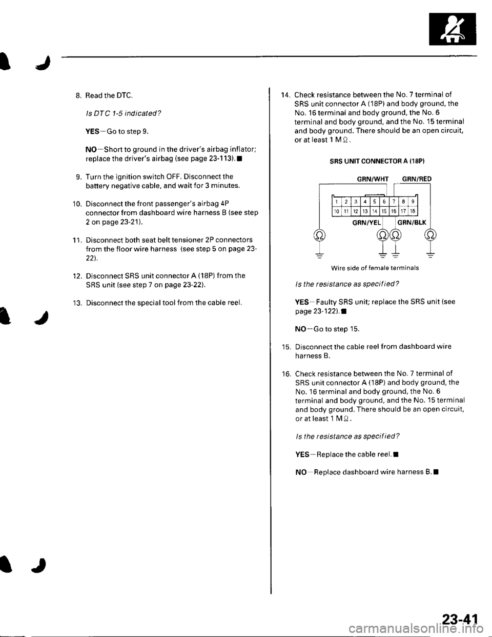
14. Check resistance between the No.7 terminal of
SRS unit connector A {18P) and body ground, the
No. 16 terminal and body ground, the No. 6
terminal and body ground. and the No. 15 terminal
and body ground. There should be an open circuit,
or at least 1 M Q.
SRS UNIT CONNECTOR A I18PI
GRN/WHT GRN/RED
16.
Wire side of female terminals
ls the resistance as specified?
YES-Faulty SRS unit; replace the SRS unit {see
page 23-1221 .f
NO-Go to step 15.
Disconnect the cable reel from dashboard wire
harness B.
Check resistance between the No.7 terminal of
SRS unit connector A (18P) and body ground, the
No. 16 terminal and body ground. the No, 6
terminal and body ground, and the No. 15 terminal
and body ground. There should be an open circuit,
or at least 1 fvl Q .
ls the resistance as specified?
YES Replace the cable reel.I
NO Replace dashboard wire harness B.l
23-41
Page 1050 of 1139
\
J
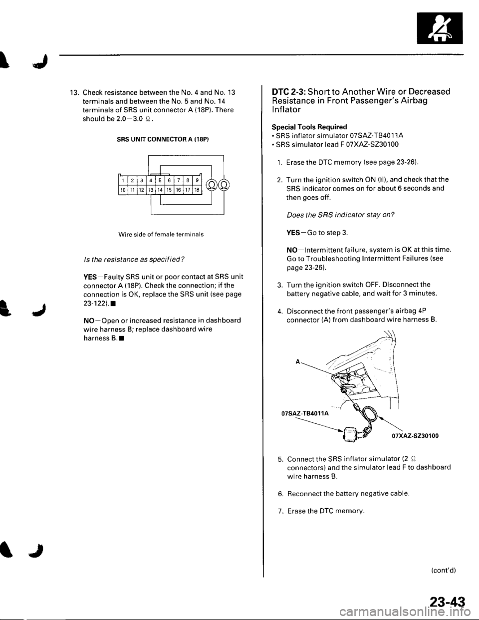
13. Check resistance between the No. 4 and No. 13
terminals and between the No.5 and No. 14
terminals of SRS unit connector A (18P). There
should be 2.0 3.0 Q.
SRS UNIT CONNECTOR A {18P)
Wire side of female terminals
ls the resistance as specified?
YES Faulty SRS unit or poor contact at SRS unit
connector A (18P). Check the connection; if the
connection is OK, replace the SRS unit (see page
23-1221.a
NO Open or increased resistance in dashboard
wire harness B; replace dashboard wire
harness B.I
TJ
23-43
DTC 2-3: Short to Another Wire or Decreased
Resistance in Front Passenger's Airbag
lnJlator
SpecialTools Required. SRS inflator simulator 07SAZ-T8401'1A. SRS simulator lead F 07XAZ-S230100
1 . Erase the DTC memory (see page 23-261.
2. Turn the ignition switch ON (ll),andcheckthatthe
SRS indicator comes on for about 6 seconds and
then goes off.
Does the SRS indicator stay on?
YES-Go to step 3.
NO Intermittent failu re, system is OK at this time.
Go to Troubleshooting Intermittent Failures {see
page 23-26).
3. Turn the ignition switch OFF. Disconnect the
battery negative cable, and wait for 3 minutes.
4. Disconnect the front passenger's airbag 4P
connector (A) from dashboard wire harness B.
07sAz-T84011A
07xAz-s230100
Connect the SRS lnflator simulator (2 0
connectors) and the simulator lead F to dashboard
wire harness B.
Reconnect the battery negative cable.
Erase the DTC memory.
(cont'd)
6.
7.
Page 1051 of 1139
sRs
DTG Troubleshooting (cont'd)
11.
Read the DTC.
ls DTC 2-3 ind icated?
YES Go to step 9.
NO-Short in the front passenger's airbag inflator;
replace the front passenger's airbag (see page 23-
114). t
Turn the ignition switch OFF. Disconnect the
battery negative cable, and wait for 3 minutes.
Disconnect the driver's airbag 4P connector from
the cable reel {see step 2 on page 23-21).
Disconnect both seat belt tensioner 2P connectors
from the floor wire harness (see step 5 on page 23-
221.
9.
10.
23-44
TJ
qJ
'12. Disconnect SRS unit connector A (18P) from the
S R S u n it (see ste p 7 on page 23-22l. .
13. Disconnectthe special tool from dashboard wire
harness B.
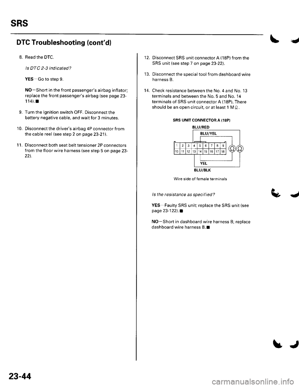
14. Check resistance between the No. 4 and No. 13
terminals and between the No. 5 and No. 14
terminals of SRS unit connector A (18P). There
should be an open circuit, or at least 1 M Q.
SRS UNIT CONNECTOR A I18P)
BLU/RED
BLU/BLK
Wire side of female terminals
ls the resistance as specitied?
YES Faulty SRS unit; replace the SRS unit (see
page 23-122)'.a
NO-Shon in dashboard wire harness B; replace
dashboard wire harness B.l
Page 1053 of 1139
sRs
13.
14.
DTC Troubleshooting (cont'd)
Disconnect SRS unit connector A (18P) from the
SRS unit (see step 7 on page 23-221.
Disconnect the special tool from dashboard wire
harness B.
Reconnect the battery negative cable.
Turn the ignition switch ON (ll).
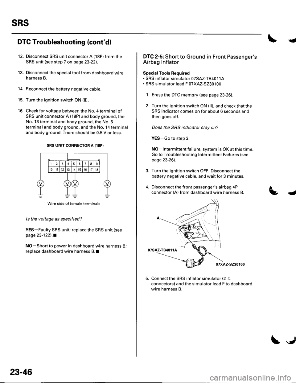
Check for voltage between the No. 4 terminal of
SRS unit connector A (18P) and body ground, the
No. 13 terminal and body ground, the No. 5
terminal and body ground, and the No. 14 terminal
and body ground. There should be 0.5 V or less.
SRS UNIT CONNECTOB A {18PI
Wire side o{ {emale terminals
ls the voltage as specified?
YES Faulty SRS uniu replace the SRS unit (see
page 23-1221 .a
NO-Short to power in dashboard wire harness B;
replace dashboard wire harness B. !
15.
to.
23-46
\J
{
DTC 2-5: Short to Ground in Front Passenger's
Airbag Inflator
SpecialTools Required. SRS inf lator simulator 07SAZ-T84011A. SRS simulator lead F 07XAZ-S230100
1. Erase the DTC memory (see page 23-26).
2. Turn the ignition switch ON (ll), and check that the
SRS indicator comes on for about 6 seconds and
then goes off.
Does the SRS indicator stay on?
YES Go to step 3.
NO Intermittent failure, system is OK at this time.
Go to Troubleshooting Intermittent Failures {seepage 23-261.
3. Turn the ignition switch OFF. Disconnectthe
battery negative cable, and wait for 3 minutes.
4, Disconnect the front passenger's airbag 4P
connector (A) from dashboard wire harness B.
07saz-T84011A
07xAz-s230100
Connect the SRS inflator simulator (2 Q
connectors) and the simulator lead F to dashboard
wire harness B.
4
5.
Page 1054 of 1139
I
7.
11.
9.
10.
Reconnect the battery negative cable.
Erase the DTC memory.
Read the DTC.
ls DTC 2-5 indicated?
YES-Go to step 9.
NO-Shon to ground in the front passenger's
airbag inflator; replace the front passenger's airbag
(see page 23-1 14).1
Turn the ignition switch OFF. Disconnectthe
battery negative cable, and wait for 3 minutes.
Disconnect the driver's airbag 4P connector from
the cable reel {see step 2 on page 23-21).
Disconnect both seat belt tensioner 2P connectors
from the floor wire harness (see step 5 on page 23-
22).
I
I
I
12.
13.
't 4.
Disconnect SRS unit connector A (18P) from the
SRS unit (see step 7 on page 23-221.
Disconnectthe special tool from dashboard wire
harness B.
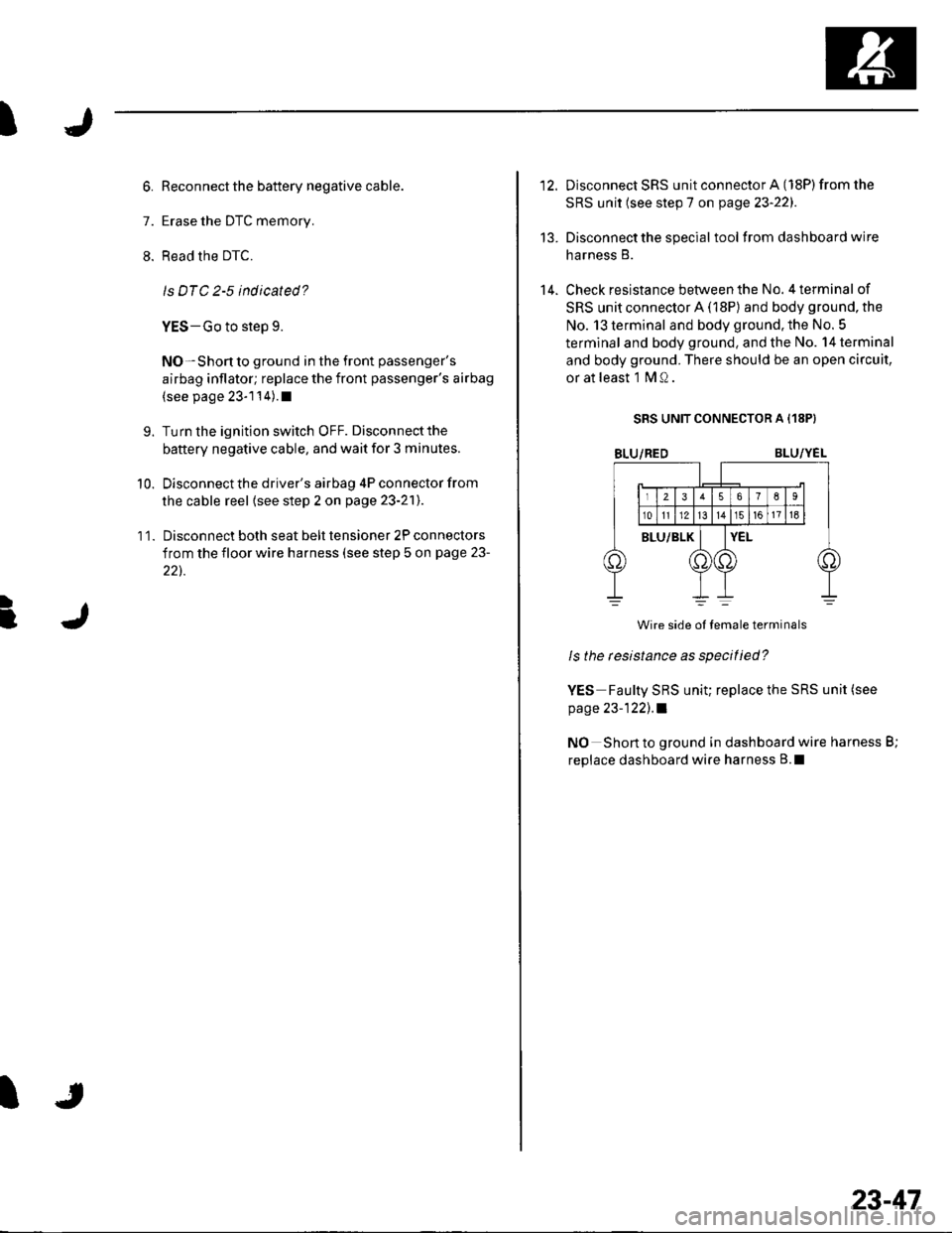
Check resistance between the No. 4 terminal of
SRS unit connector A (18P) and body ground, the
No. 13 terminal and body ground. the No. 5
terminal and body ground, and the No. 14 terminal
and body ground. There should be an open circuit,
or at least l MQ.
SRS UNIT CONNECTOR A {18P}
BLU/REDBLU/YEL
Wire side ol temale terminals
ls the tesistance as specitied?
YES Faulty SRS uniu replace the SRS unit (see
page 23-122), .l
NO Short to ground in dashboard wire harness B;
replace dashboard wire harness B.l
23-47
Page 1056 of 1139
I
17.
Oisconnect the driver's airbag connector (see step
2 on page 23-21), f ront passenger's airbag
connector (see step 3 on page 23-21), andfront
passenger's seat belt tensioner connector (see step
5 on page 23-22).
Disconnect SRS unit connector A (18P) from the
SRS unit (see step 7 on page 23-22). Do not
disconnect the special tool from dashboard wire
harness B.
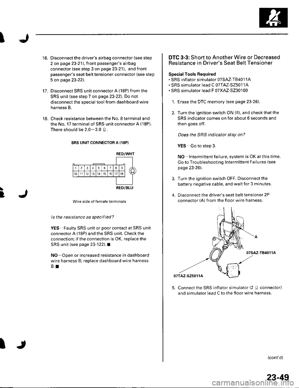
Check resistance between the No.8 terminal and
the No. 17 terminal of SRS unit connector A (18P).
There should be 2.0-3.0 Q.
SRS UNIT CONNECTOR A (18P)
RED/WHT
i-4\lel a;
Ea
23561
101l1Zt3t516
RED/BLU
Wire side of female terminals
ls the resistance as specitied?
YES Faulty SRS unit or poor contact at SRS unit
connector A (18P) and the SRS unit. Check the
connection; if the connection is OK, replace the
SRS unit (see page 23-'1221.a
NO Open or increased resistance in dashboard
wire harness B; replace dashboard wire harness
B,t
18.
I
]
I
to.DTC 3-3: Short to Another Wire or Decreased
Resistance in Driver's Seat Belt Tensioner
SpecialTools Required. SRS inflator simulator 07SAZ-T8401'1A. SRS simulator lead C 07TM-S25011A. SRS simulator lead F 07XAZ-S230100
1. Erase the DTC memory (see page 23-26).
2. Turn the ignition switch ON (ll), and checkthatthe
SRS indicator comes on for about 6 seconds and
then goes off.
Does the SRS indicator stay on?
YES Go to step 3.
NO-lntermittent failure, system is OK at this time,
Go to Troubleshooting Intermittent Failures {see
page 23-26).
Turn the ignition switch OFF. Disconnect the
battery negative cable, and wait for 3 minutes.
Disconnect the driver's seat belt tensioner 2P
connector (A) from the floor wire harness.
-T84011A
07TAZ-S25011A
5. Connect the SRS inflator simulator (2 0 connector)
and simulator lead C to the floor wire harness.
(cont'd)
23-49
Page 1057 of 1139
sRs
DTC Troubleshooting (cont'd)
6. Reconnectthe battery negative cable.
7. Erase the DTC memory.
8. Read the DTC.
ls DTC 3-3 indicated?
YES-Go to step L
NO-Shon in the driver's seat belt tensioner;
replace the driver's seat belt (see page 23-4).1
L Turn the ignition switch OFF. Disconnectthe
battery negative cable, and wait for 3 minutes.
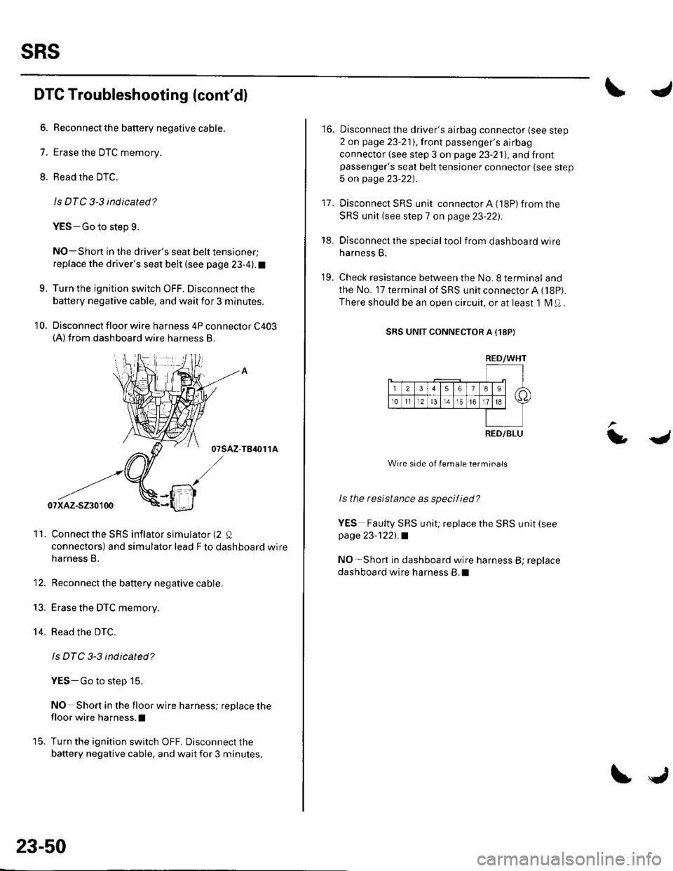
10. Disconnect floor wire harness 4P connector C403(A)from dashboard wire harness B.
07sAz-TB4or 1A
Connectthe SRS inflator simulator (2 Q
connectors) and simulator lead F to dashboard wire
harness B.
Reconnect the battery negative cable.
Erase the DTC memory.
Read the DTC.
ls DTC 3-3 indicated?
YES-Go to step 15.
NO Short in the floor wire harness; replace the
floor wire harness.l
Turn the ignition switch OFF. Disconnect the
battery negative cable, and wait for 3 minutes.
11.
13.
14.
23-50
tJ
16. Disconnect the driver's airbag connector (see step
2 on page 23-211,lront passenger's airbag
connector (see step 3 on page 23-21), and frontpassenger's seat belt tensioner connector (see step
5 on page 23-22).
17. Disconnect SRS unit connector A (18P) from the
SRS unit (see step 7 on page 23-22:,.
18. Disconnect the special tool from dashboard wire
harness B.
19. Check resistance between the No.8 terminal and
the No. 17 terminal of SRS unit connector A ('l8P).
There should be an open circuit, or at least 1 l\4 Q .
SRS UNIT CONNECTOR A I18P)
Wire side of female terminals
ls the resistance as specif ied?
YES Faulty SRS unit; replace the SRS unit (see
page 23-1221.a
NO- Short in dashboard wire harness B; replace
dashboard wire harness B.l
LJ
RED/WHT
RED/BLU