Page 899 of 1139
Exterior Lights
Gomponent Location Index
UNDER.HOODFUSE/RELAY BOX
\/
HEADLIGHTSReplacement, page 22 79Adjustment. page 22-78Eulb Replacement, page 22-81
HEADLIGHT RELAY 1Test, page 22-51
HEADLIGHT RELAY 2Test, page 22-5'l
0/
FRONT SIDE MARKER LIGHTBulb Replacement, page 22 83
BRAKE PEDAL POSITIONswtTcHTest, page 22-84Adjustment, page l9'6
SIDE TURN SIGNAL LIGHTReplacement, page 22-84
FRONT TURN SIGNALLIGHTBulb Beplacement, page 22 81
PARKING LIGHTBulb Replacement, page 22-81
22-68
Page 901 of 1139
Exterior Lights
Component Location Index (cont'dl!
DAYTIME RUNNING LIGHTS RELAY {Canadal[Wire colors: RED, REDryEL, ILRED/BLK and RED/BLU ITest, page 22-51
_LOW BEAM CUTRELAY {Canadal _Wire colorsr REDMHT, RED/BLK, ILREDryEL and RED/BLU ITest, page 22-51
DASH LIGHTS BRIGHTNESSCONTROLLER
/
COMBINATION LIGHT SWITCHTesVReplacement, page 22-80
oAYTIME RUNNING LIGHTS CONTROL UNIT lcanada)Input Test, page 22-76
DRL INDICATOR LIGHT {Canadal
HIGH BEAM INDICATOR LIGHTBulb Replacement, page 22-63
UNDER.DASH FUSE/RELAY BOX
:' --,': - '
' i,-'-'l
..i \
I t- -
22-70
Page 916 of 1139
Turn Signal/Hazard Flasher
Component Location Index
COMBINATION LIGHT/TURN SIGNAL SWITCHTest, page 22-80Beplacement, page 22-80
TURN SIGNAL INDICATOR LIGHTS(ln the gauge assembly)Bulb Replacement, page 22'63
HAZARD WARNING SWITCHTest, page 22-88Replacement, page 22-88
TURN SIGNAL/HAZARD RELAYInput Test, page 22-87
UNDER.DASH FUSE/RELAY BOX
22-85
Page 935 of 1139
Rear Window Defogger
J
I
Component Location Index
*:Rear window defogger switch is built into the heater control panel.
UNDER.HOOD FUSE/RELAY BOX
REAR WINDOWDEFOGGER SWITCH+
t
REAR WINDOW DEFOGGER RELAYTest, page 22-51
u
NOISE CONDENSERCapacityTest, page 22 107
REAR WINDOW DEFOGGEBFunction Test, page 22 106Defogger Wire Repair, page 22 106
22-104
J
Page 951 of 1139
Horns
\Component Location Index
HORN RELAYTest, page 22-51
HORNSTest, page 22 122Beplacement, page 22 122
UNDER-HOOD FUSE/RELAY BOX
.- :.."'
HORN SWITCHfesl, page22-122
CABLE REELReplacement, page 23,1 19
22-120
*r
Page 955 of 1139
Power Windows
IJComponent Location Index
DRIVER'S WINDOW MOTORTest, page 22-129
UNDER.DASHFUSE/RELAY BOX
POWER WINDOW RELAYIest, page 22-51
FRONT PASSENGER'SWINDOW MOTORTest, page 22-132
tJ
POWER WINDOW MASIER SWITCHInput Test. Daqe 22.126Test, page 22--128Replacement, page 22-133
FRONT PASSENGER'S WINDOW SWITCHInDut Tesl, paqe 22-130f est, page 22-132Beplacement, page 22-133
al.l ' -f..--.--
L-.::
22-124
\J
Page 965 of 1139
Wipers/Washers
Component Location Index
WINDSHIELD WIPER MOTORTest, page 22-'143Replacement, page 22-145
WINDSHIELD WIPER ARMS and LINKAGEReplacement, page 22-'145
WIPER/WASHER SWITCHTest, page 22-140Replacement,page 22 140
UNDER.DASHFUSE/RELAY BOX
INTERMITTENT WIPER CIRCUITlln the multiplex control unit)Input Test, page 22-138
22-134
Page 1133 of 1139

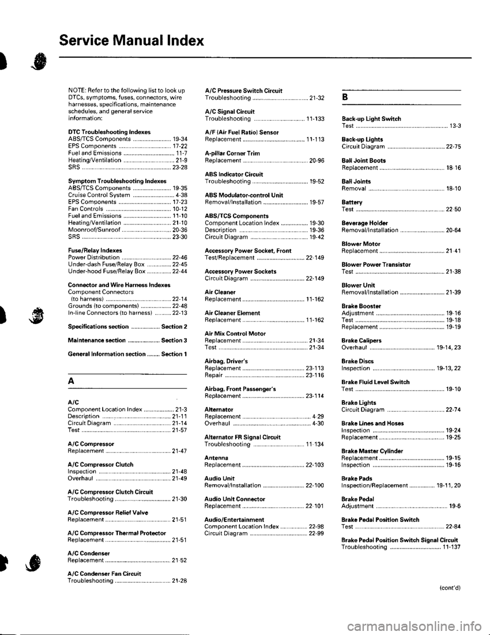
Service Manual lndex
)s
NOTE: Referto the lollowing listto look up A/C Pressure Switch CircuitDTCS, symptoms, fuses, connectors, wire Troubleshooting ......... ...-.-....-...-.-.-....-..21-32 Bharnesses, specifications, maintenanceschedules, and general serviceinlormation:
DTC Troubleshooting Indexes
A/C Signal CircuitTroubleshooting.........................-...... 11-'133 Back-up Light SwitchTest .......................................................... 13'3A/F lAir Fuel Ratiol SensorABS/TCS Components ........................ 19-34 Replacement ....................................... 1 1-113 Back-up Li9ht3EPS Components ................................. '17-22 Circuit DiagramFueland Emissions11-i A-Dillar Corner Trim
ABS Indicator Circuit
Heating/Ventilation ................................ 21-9 Replacement ...............-.....-..............-.... 20,96 Ball Joint BootssRS ........................................................ 23-28Replacement ......
... 19-52 Ball Joints
22-75
18 16
Remova1.............-.......... . ...........18-10Symptom Troubleshooting Indexes TroubleshootingABS/TCSComponents........................ 19 35Cruise Control System ..........................4 38 ABS Modulator-contml UnitEPS Components ................................. 17-23 Bemoval/lnstallation ............................ 19-57 BettervFan Controls10,12
Accessory Powor Socket Front
Blowor Pow€r Transistor
.......22 50
Blower UnitRemoval/lnstallation ............................ 21-39
Fuel and Em issions .............................. 11-10 ABS/TCS ComoonentsHeating/Ventilation..............................21 10 Component Location Index ................. 19-30 Beverage Holder
SRS ........................................................ 23'30 CircuitDiaqram.......................... 19'42Blower MotorReplacement .....21 41
21-38
Power 0istribution ...............................22-46 TesVReplacement .............................. 22'149Under-dash Fuse/Relay Box ............... 22 45Under-hood Fuse/Belay Box ...............22 44 Accessory Power Sockets
Fuse/Relay lndexes
(to harness)
Connector and Wire Harness lndexesComponent Connectors
Circuit Oiagram .................................. 22-149
Air Cleaner......2214 Rep1acemen1.....................................11-162
Air MixControl MotorMeintenence section .................... Section 3 Replacement ......................................... 21'34 Brake CelipersTest......................21-34 Overhaul19-14,23Gene.al lnlormation section........ Section 1
21.57
Airbag. Driver's
Ahernator FR Signal CircuitTroubleshooting .... .........-..........11 134
AntennaReplacement
Inspection ............................................. 19-24Rep|acement................. .................... 19-25
Bieke Meder Cylinder
Irake Discs
A
Replacement ....................................... 23 1 'l3 Inspection .................... ................... 19-13,22Repair ...........-...................................... 23 1 16Brake Fluid Level SwitchAirbag. Front Passenger's TestBeplacement....................................... 23-1 14AIC Brake LightsComponent Location fndex ...................21-3 Altemator CircuitDiagram....................................22-74Description.....................................-....21'1'l Beplacement ................ ........................... 4 29CircuitDiagram....................................21-14 Overhaul .................................................4-30 Brake Lines and Hoses
19.10
A/C CompressolReplacement .......-...-............................. 21 -41
A/C Compr€ssor ClulchRep1acement......................................... 19-15.........22-103 Inspection ............................................. 19-16Inspecton........Overhaul ..........
A/C CondenserReplacement,.,
21-442l-49 Audio Unit
Replacement
Brake PadsRemoval/lnstallation .. ........................22-100 Inspection/Rep1acement................ 19-11,20A/C Compressor Clutch CircuitTroubleshooting ................................... 21-30 Audio Unit Connector Brake Pedal22101 Adjustment..............19,6ArfC Comoressor Relief ValvcReplacement ..........-...-.......................... 21-51 Audio/Entertainment
A/C Compr$sor Thermal Protector Circuit DiagramReplacement............-............................ 21-51
Component Location In dex .................22-9A Test .......-.............. 22-84Breke Pedal Posilion Switch
Brake Pedal Position Switch Signal Clrcuit11-137
.....21 52
A/C Condenser Fan CircuitTroubleshooting ................... . . . . . .....21-28
)s
Troubleshooting
(cont'd)