Page 144 of 1139

Engine Block
Crankshaft Main Bearing Replacement
Main Bearing Clearance Inspection
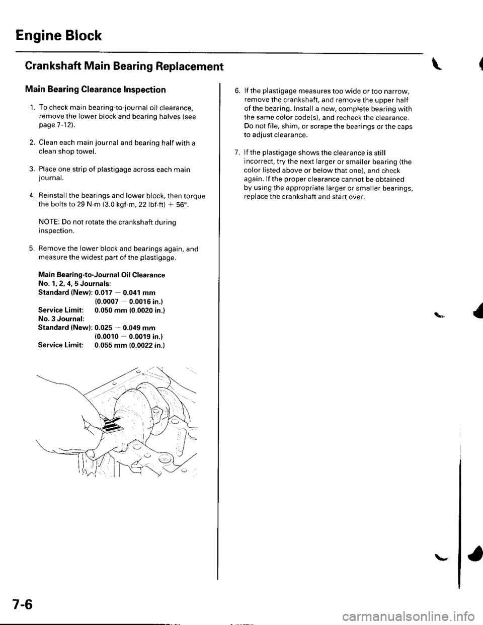
1. To check main bea ring-to-jou rna I oil clearance.
remove the lower block and bearing halves (see
page 1 -12)..
2, Clean each main journal and bearing half witha
clean shop towel.
3. Place one strip of plastigage across each main
lou rnal.
4. Reinstallthe bearings and lower block, then torque
the bolts to 29 N.m {3.0 kgf.m,22 lbf.ft) + 56'.
NOTE: Do not rotate the crankshaft during
Inspeclton.
5. Remove the lower block and bearings again, and
measure the widest part of the plastigage.
Main Bearing-to-Journal Oil Clearance
No. 1,2, 4,5 Journals:
Standard (New): 0.017 0.041 mm
Service Limit:
No.3 Journal:
10.0007 0.0016 in.l
0.050 mm {0.0020 in.)
Standard {Newl: 0.025 - 0.049 mm(0.0010 0.0019 in.)
Service Limit: 0.055 mm (0.0022 in.l
7-6
\.
6. lf the plastigage measures too wide or too narrow,
remove the crankshaft. and remove the upper half
ofthe bearing. Install a new, complete bearing with
the same color code{s), and recheck the clearance.
Do not file, shim, or scrape the bearings or the caps
to adjust clearance.
7. lf the plastigage shows the clearance is still
incorrect, try the next larger or smaller bearing (the
color listed above or below that one), and check
again. lf the proper clearance cannot be obtained
by using the appropriate larger or smaller bearings,
replace the crankshaft and start over.
Page 146 of 1139

Engine Block
Crankshaft Main Bearing
Replacement (cont'd)
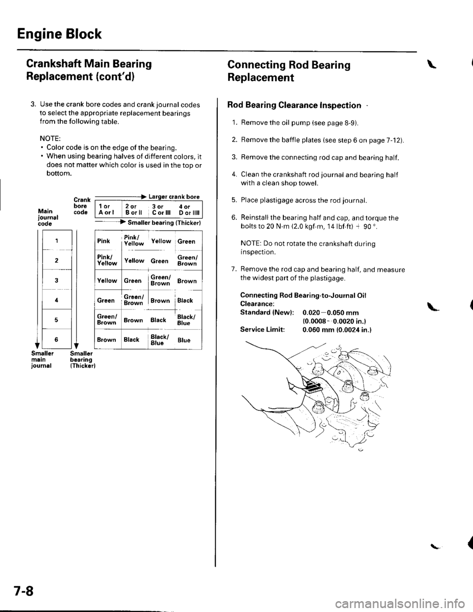
3. Use the crank bore codes and crank journal codes
to select the appropriate replacement bearings
from the following table.
NOTE:. Color code is on the edge of the bearing.. When using bearing halves of different colors. it
does not matter which color is used in the top or
bottom.
Mainiournslcooe
Crank ---=-> Lalger crank bore
bore | 1or 2ot 3or c oi__-lcode IAorl Borll Corlll Dortttt I-- --> Smaller bearing {Thickerl
(Thicker)
1
2
4
5
Pink f!1f;* v"rro* c,""n
ll
f111f;,," v"no* c,""" $;;fl
cr""n $ffi ero-n
ffi#Tr,.*" i.,""*Creen ; g=jiff;i Brown Black
;;lT]*
'---l-'o"*,
Brown Black 6il;
Brack !l;kr ar*
7-8
Connecting Rod Bearing
Replacement
Rod Bearing Clearance lnspection
1. Remove the oil pump (see page 8-9).
2. Bemove the baffle plates (see step 6 on page 7-12).
3. Remove the connecting rod cap and bearing half.
4. Clean the crankshaft rod journal andbearinghalf
with a clean shop towel.
5. Place plastigage across the rod journal.
6. Reinstallthe bearing half and cap, and torque the
bolts to 20 N.m (2.0 kgf.m, 14lbf.ft) -l 90 ".
NOTE: Do not rotate the crankshaft during
inspection.
7. Remove the rod cap and bearing half, and measure
the widest part of the plastigage.
Connecting Rod Bearing-to-Journal Oil
Clearance:
Standard {Newl: 0.020 0.050 mm(0.0008 --0.0020 in.l
Service Limit: 0.060 mm (0.0024 in.)
\
\-
{
Page 179 of 1139

8.
9.
6. Clean both balancer shaft No. 2 journals and
bearing halves with a clean shop towel.
7. Place one strip of plastigage across each No.2journal.
Reinstall the bearings and upper balancer shaft
holder, then torque the bolts.
NOTE; Do not rotate the balancer shaft durinq
insDection.
Remove the uooer balancer shaft holder and
bearings again, and measure the widest part of the
plastigage. lf the balancer shaft No. 2 journal oil
clearance is out-of-tolerance. install the new
bearings, and recheck. lf it is still out-of-tolerance,
replace the balancer shafts.
No. 2 Journal Oil Clearance:
Standard lNewl; 0.060 0.120 mm
Service Limit:
(0.0024 0.0047 in.l
0.15 mm {0.006 in.)
10. Align the punch mark on the rear balancer shaft
with the center of the two punch marks on the front
balancer shaft, then install'the balancer shafts in
the lower balancer shaft holder
Apply engine oil to the threads of the 8 mm bolts(A).
6x1.0mm'12 N.m(1.2 kgt.m, 8.7 lbt ft)
11.
Installthe upper balancer shaft holder (B) and
bafile plate (C).
(cont'd)
12.
8-13
Page 351 of 1139

FuelSupply System
Fuel Pressure Relieving
Before disconnecting fuel lines or hoses, relieve
pressure from the system by disconnecting the fuel
tube/quick connect fitting in the engine compartment.
1. Turn the ignition switch OFF,
2. Remove the PGM-Fl main relay 2 (A).
Startthe engine, and let it idle until it is stalls.
NOTE: The DTCS or Temporary DTCS P0301. P0302,
P0303, P0304 may come on during this procedure.
lf any DTCS are stored, ignore them.
Turn the ignition switch OFF.
Remove the fuel fill cap, and relieve fuel pressure
in the fueltank.
Remove the engine cover.
Disconnect the negative cable from the battery.
Check the fuel quick-connect fitting for dirt, and
clean it if necessary.
3.
4.
6.
7.
8.
11-144
11
10.
9. Place a rag or shop towel over the quick-connect
fitting (A).
Disconnect the quick-connect fifting (A): Hold the
connector (B) with one hand and squeeze the
retainer tabs (C) with the other hand to release
them from the locking pawls {D). Pullthe connector
off.
NOTE:. Prevent the remaining fuel in the fuel feedlineor
hose from flowing out with a rag or shop towel.. Be careful notto damage the line (E) or other
pa rts.. Do not use tools.. lf theconnectordoes not move, keepthe retainer
tabs pressed down, and alternately pull and push
the connector until it comes off easily.. Do not remove the retainer from the line; once
removed, the retainer must be replaced with a
new one.
After disconnecting the quick-connect fifting, check
it for dirt or damage (see page 1 1-149).
Page 355 of 1139

Fuel Supply System
Fuel Line/Ouick-Connect Fittings Precaution
The fuel tube/quick-connect fittings connect the fuel rail(A)to fuel feed hose (B), the fuel feed hose (B) to the
fuel line (C), and the fueltube (D) to the fuel pump
assembly (E). When removing or installing the fuelfeed
hose, fuel pump assembly, or fuel tank, it is necessary
to disconnect or connect the quick-connect fittings.
Pay attention to the following:
. The fuel feed hose (B), fuel tube (D), and quick-
connect fittings (F) are not heat-resistanU be careful
not to damage them during welding or other heat-
generalrng proceoures.
. The fuelfeed hose (B), fueltube (D) andquick-
connect fittings (F) are not acid-proof; do not touch
them with a shop towel which was used for wiping
battery electrolyte. Replace them if they came into
contact with electrolyte or something similar.
. When connecting or disconnecting the fuel feed hose(B), fuel tube (D), and quick'connect fittings (F). be
careful not to bend or twist them excessivelv. ReDlace
them it they are damaged.
11-148
A disconnected quick-connect fitting can be
reconnected, but the retainer on the mating line cannot
be reused once it has been removed from the line.
Replace the retainer when
. replacing the fuel rail.. replacing the fuel line.. replacing the fuel pump.
. replacing the fuel filter,. replacing the fuel gauge sending unit.. it has been removed from the line.. it is damaged.
PARTI\4ANUFACTUREBRETAINER
COLOR
E NG INE
COI\4PARTMENT(FUEL FEED
HOSE; FU EL
LINE SIDE)
TOKAIGREEN
EN G INE
COIVIPARTMENT(FUEL FEED
HOSE: FUEL
RAIL SIDE)
TOKAIBLU
FUEL TANK
UNIT
SANOHWHITE
I
Page 402 of 1139

Clutch Master Cylinder Replacement
NOTE: Do not spill brake fluid on the vehicle; it may
damage the paint; if brake fluid does contact the paint,
wash it off immediatelV with water.
1. Pry out the lock pin (A), and pullthe pedal pin (B)
out of the yoke. Remove the master cylinder
mounting nuts (C).
Remove the air cleaner housing cover and the air
cleaner housing (see step 6 on page 5-2).
Remove the brake fluid from the clutch master
cylinder reservoir with a syringe.
Remove the clutch line bracket from the frame rail,
and remove the clutch line clip.
Remove the clutch master cylinder (A), and pull it
toward the middle of the engine compartment.
Remove the retaining clip (B). Disconnect the clutch
line (C). Plug the end of the clutch line with a shop
towelto prevent brake fluid from coming out.
g-E
3.
6. Disconnect the reservoir hose (D) fromtheclutch
master cylinder reservoir. Plug the end of the
reservoir hose with a shop towel to prevent brake
fluid from coming out.
7. Remove the O-ring (E) and the clutch master
cylinder seal (F) from the master cylinder.
8. Installthe clutch master cylinder in the reverse
order of removal. Install a new O-ring.
9. Make sure the hose clamps (A) are positioned on
the master cylinder (B) and reservoir (C) as shown.
(cont'd)
UP
i
12-5
Page 404 of 1139

Slave Cylinder Replacement
NOTE:. Use fender covers to avoid damaging painted
surfaces.. Do not spill brake fluid on the vehicle; it may damage
the paint; if brake fluid does contact the paint, wash it
off immediately with water.
1. Write down the frequencies for the radio's preset
buttons. Disconnect the negative ( ) cable first,
then the positive (+)cable from the battery.
Remove the battery.
2. Remove the battery tray.
a
Remove the air cleaner housing cover and the air
cleaner housing (see step 6 on page 5-2).
Remove the intake air duct (see step 8 on page 5-3) .
Remove the clutch line bracket (A).
4.
5.
6. Remove the mounting bolts (A) andtheslave
cylinder (B).
Remove the roll pins (C). Disconnect the clutch line(D), and remove the O-ring (E). Plug the end of the
clutch line with a shop towel to prevent brake fluid
f rom coming out.
Installthe slave cylinder in the reverse order of
removal. Install a new O-ring (A).
7.
,,6NJ'
=--#.q!4sEn(P/N 08798-90021
9.
(Brak6 Assembly Lube)
Pullthe boot (B) back, and apply brake assembly
lube to the boot and slave cylinder rod (C). Reinstall
the boot.
Apply super high temp urea grease (P/N 08798-
9002) to the push rod of the slave cylinder. Tighten
the slave cylinder mounting bolts to 22 N m (2.2
kgf m, 16lbf.ft).
(cont'd)
12-7
10.
Page 430 of 1139
Manual Transmission
Change Lever Assembly Disassembly/Reassembly
Prior to reassembling, clean all the parts in solvent, dry them, and apply lubricant to any contact surface.
BREATHER CAPTurn the arrow toward the {ronto{ the vehicle, and install it.
SELECT LEVERBe careful not to damage the dust sealwhen installing it.@).1 IlLrl
rrl
I
DUST COVEB
a^^
7 Fr"irr6-rooa
(P/N 08798-9002)
ROLLER
6x1.0mm12 N.m(1.2 kgl.m,8.7 lbf.ft)
'^ E-='-Fl !-d 1sr/2Noq )-=^l sELEcr
i €2 sPntruc
,.* (A)tace. ix�#,,l
H\
lV srxSELECT-z:-=:l-': SPRING
r\
tr7
,/u
/
\op
(g)'
' -, OIL SEAL,/ ReDlace./-r,s
\__/
INTERLOCK
SHIFT ARM
SELECT STOPPLATE
REVERSE LOCK CAMSTRIKER
SHIFT ARM COVER
WASHER
9.8Nm{1.0 kgf.m, 7.2 lbf.ft)
13-20