2003 HONDA CIVIC plate light
[x] Cancel search: plate lightPage 879 of 1139

Ground Distribution
Ground to Components Index
GroundComponent or circuit qrounded
Batterv, Transmission housinq
E ngine
G 101ECM (PG is BLK; LG is BRN/YEL)
BLK: IAC valve, lgnition coils, Vehicle speed sensor, VTEC solenoid valve
BRNA/EL: Camshaft oosition (CMP) sensor. CKP sensor, TDC sensor. VTEC oil pressure switch
G 15'�]EPS control unit
G201ELD unit. Multiplex control inspection connector, Multiplex control unit, Power window relay, Rear
window washer motor, Right front parking light, Right front side marker light, Right front turn signal
light, Turn signal/hazard relay, Washer fluid level sensor (Canada) , Windshield washer motor,
Windshield wiDer motor
G202ABS modulator-control unit
G301
G401
Blower motor relay, Brake fluid level switch, Condensor fan motor, Cruise control actuator, Left front
parking light, Left front side marker light, Left front turn signal light, Radiator fan motor, Radiator fan
swrtcn
Combination liqht switch, lqnitlon kev srvitch, Wiper/wasfrer sr,virch
G402Left and riqht airbaq sensors, SRS unit
G 451Data link connector (DLC)
G501Clutch interlock switchm Clutch pedal position switch (for cruise control), Cruise control main switch,
Cruise control unit, Daytime running lights control unit (Canada), Driver's door lock knob switch,
Driver's door lock switch, Driver's power window motor, Heater control panel, Left power mirror
defogger (Canada), left side turn signal light, Moonroof control unit, Monroof open and close relays,
Moonroof position sensor '1, Moonroof seitch, Power mirror switch, Power transistor, Power window
master switch. SDotliqhts
G502Accessory power socket, Gauge assembly, Keyless receiver unit, lvlultiplex control unit, Right power
mirror defogger {Canada)
G503Audio unit
G551Driver's seat belt switch, Fuel gauge sending unit, Fuel pump, Memory erase signal (IMES) connector,
OPDS unit. Rioht seat belt switch
G552High mount brake light, License plate lights, Rear window defogger, Rear window defogger noise
condenser. Rear window wioer motor, Hatch latch switch
Back-up lights, Brake lights, Rear side marker lights, Rear turn signal lights, Rear window wiper noise
condenser, Rear window wiper intermittent control unit, Taillights
22-48
Page 900 of 1139

-a-.,_
z
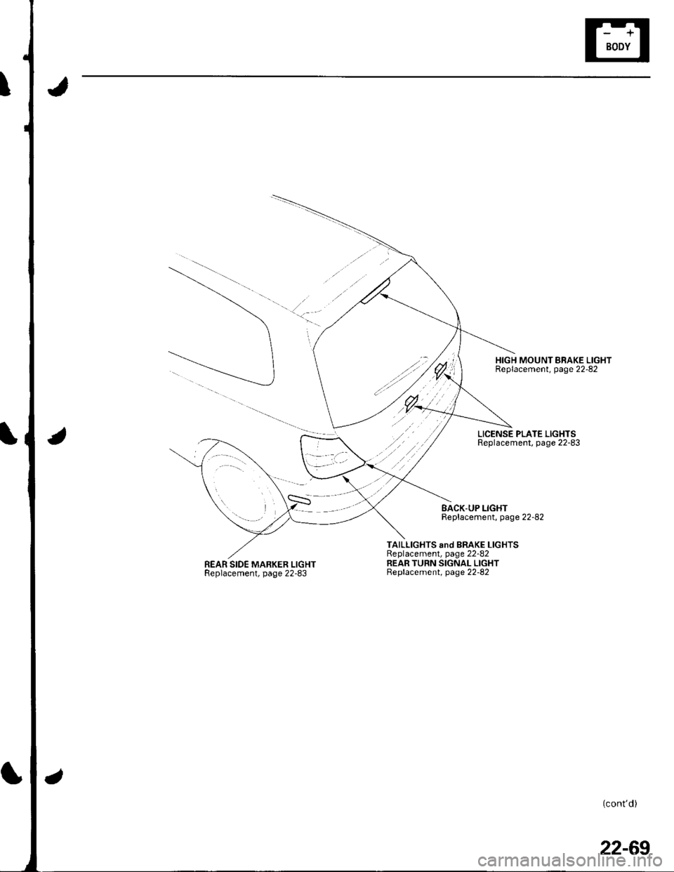
REAR SIDE MARKER LIGHTReplacement, page 22-83
HIGH MOUNT BRAKE LIGHTReplacement, page 22-82
LICENSE PLATE LIGHTSReplacement, page 22-83
BACK.UP LIGHTReplacement, page 22-82
TAILLIGHTS snd BRAKE LIGHTSReplacement, page 22-82REAR TURN SIGNAL LIGHTBeplacement, page 22-82
(cont'd)
22-69
Page 914 of 1139

License Plate Light Replacement
1.Remove the hatch lower trim panel (see page 20-
Pullthe license plale light assembly out. and
disconnect the 2P connector (A) from the light.
License Plate Light: 5Wx2
3.
4.
'[-J^,^f , t lo \
+tiP'-t \-J'fl^
"/ \==-^
Separate the lens (B) and housing (C), then remove
the bulb.
lnstallthe light in the reverse order of removal.
Side Marker Light Replacement
1. Carefully pry the light (A) outofthe rear bumper,
and disconnect the 2P connector (B) from the light.
Be careful not to damage the rear bumper.
Side Marker Light:5W
2.Remove the bulb socket (A) by turning it 45'
counterclockwise. then reolace the bulb.
22-83
Page 987 of 1139

Keyless/Power Door Lock System
Control Unit Input Test (cont'dl
5. Reconnect all connections to the underdash fuse/relay box, and make these input tests at the appropriate connectors on the under-dashfuse/relay box.
'lfanytestindicatesaproblem,findandcorrectthecause,thenrecheckthesystem.. lf all the inputtests prove OK, goto step 6.
CavitvWireTest conditionTest: Desired resultPossible ca use if result is notobtainedc1'l8LUUnder all conditionsAftach to ground:Parking, side marker, licenseplate lights, and tajllights shouldcome on.
Blown No.2 (15A)fuse in the underhood fuse/relay boxFaulty taillight relayFaulty under-dash fuse/relay boxAn onen in rhc wireBLU/BEOUnder all conditionsAttach to ground:Headlights should come on.Blown No. 15 or 17 (15A)fuse in theunderhood fuse/relay boxFaulty headlight relay '1 or 2An ooen in the wireJ2WHT/REDUnder all conditionsCheck for voltage to ground:There should be battery voltage.Blown No.9 (15A)fuse in the under-hood fuse/relay boxAn oncn in thc wircBLKUnder all conditaonsCheck for voltage to ground:Thcre shouln hc 1 V or lpqsPoor ground (G501)An ooen in the wireJ6OBNUnder allconditionsAttach to ground:The horns should sound.Blown No. 7 (15A)fuse in the underhood fuse/relay boxFaulty horn relayFaulty hornsAn 6nen in rhe wireJ7Under all conditionsCheck for voltage to ground:There should be battery voltage.Elown No. 16 (20A)fuse in the underhood fuse/relay boxAn oocn in ihc wi.cP18BEDHatch openCheck for voltage to ground:There should be 1 V or less.Poor ground (G552)Faulty hatch latch switchAn oncn in rhc wirFHatch closedCheck for voltage to groundlThere shoul.l he 5 V or moreFaulty hatch latch switch
GBNDriver's door openCheck for voltage to g.ound:There should be 1 V or less. Faulty driver's door switch. An ooen in the wireDriver's door closedCheck for voltage to ground:There should be 5 V or more.Faulty driver's door switchShort to oroundo4LT GRN/REDPassenger's door openCheck for voltage to ground:There should be 1 V or less.Faulty passenger's door switchAn ooen inthewirePassenger's door closedCheck for voltage to groundlThere should be sVor more
. Faulty passenger's door switch. Short to oroundX5REDAVHTlgnition key inserted intothe ignition swhchCheck for voltage to ground:There should be 1 V or less.Poor ground {G401)Faulty ignition key switchAn ooen inthewirelgnition key removed fromrhe ionition switchCheck for voltage to ground:There should be 5 V or more.Faulty ignition key switchShort to oroundY1WHT/BLKDriver's door lock knobswitch unlockedCheck for voltage to groundlThere should be 1 V or less.Poorground (G50'l)Faulty driver's door lock knob switchAn open in the wireDriver's door lock knobCheck for voltage to groundlIhere should be 5 V or more.Faulty driver's door lock knob switchShort to oroundY8YEUREDDriver's door lock knobswitch lockedCheck for voltage to groundlThere should be 1 V or less.Poorground (G50'l)Faulty driver's door lock knob switchAn oncn inihewireDriver's door lock knobswitch unlockedCheck for voltage to ground:There should be 5Vor more' Faulty driver's door lock knob sw;tch. Shorr to oroundY10WHT/GRNDrtver's door lock switchunlockedCheck for voltage to groundlThere should be 1 V or less.Poorground (G501iFaulty driver's door lock switchAn ooen in the wireDriver's door lock switch inCheck for voltage to ground:Therc shorl.l be 5V or m6rpFaulty driver's door lock switchShort to o rolrndY12WHT/BLUDriver's door lock switchlockedCheck for voltage to ground:There should be 'l V or less.Poor ground (G501)Faulty driver's door lock switchAn oDen in the wireDriver's door lock switch inCheck tor voltage to ground:There should be 5Vor moreFaulty driver's door lock switch
22-156
J
Page 1136 of 1139

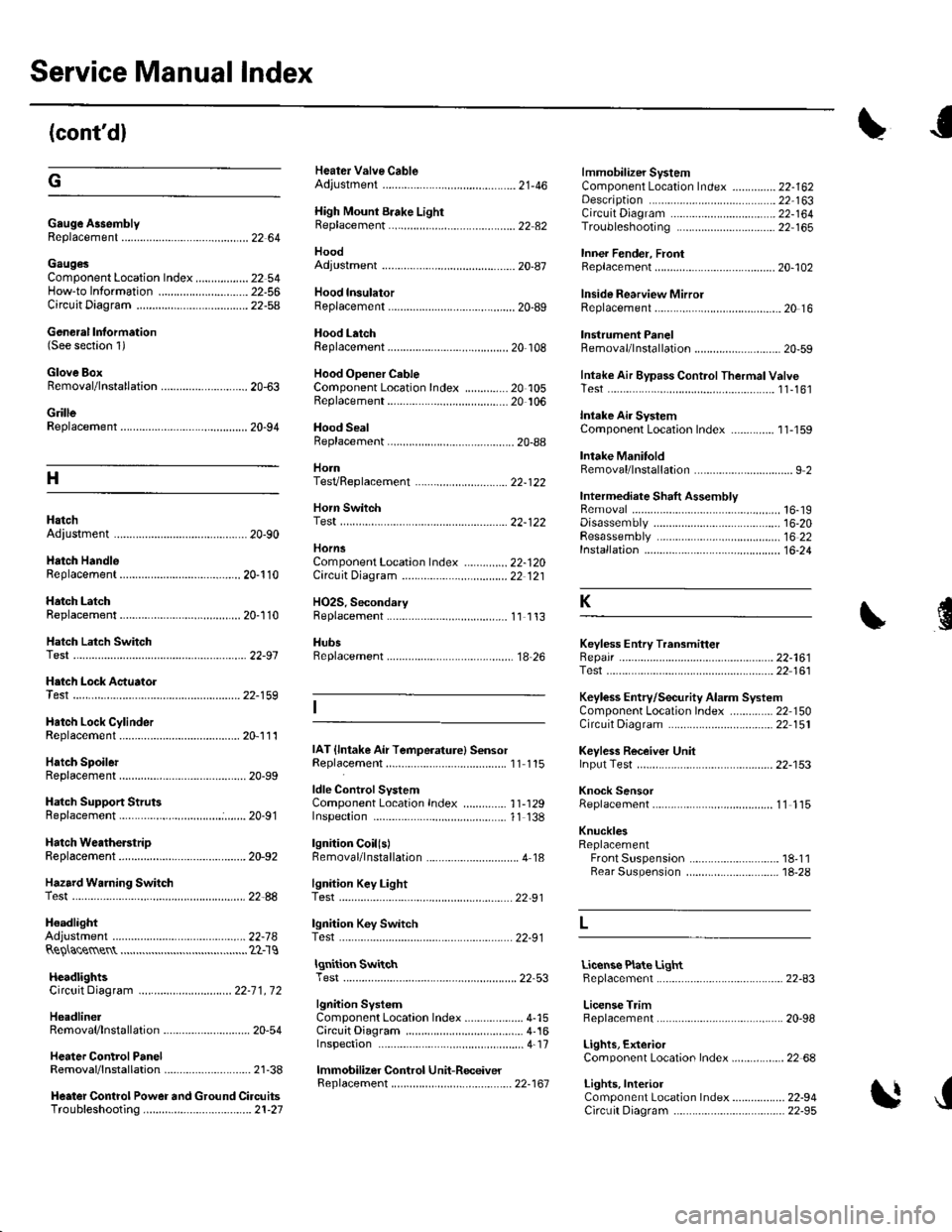
Service Manual Index
(cont'dl
Gauge A3semblyReplacement......................................... 22 64
Gaug€sComponent Location Index ..........-...... 22 54How-to lnformation ........................22-56Circuit Diagram22-54
Heater Valve CableAdjustment ...................... .................... ?1-46
High Mount Brake Light8ep|acement......................................... 22 82
Hood
lmmobilizer SystemComponent Location In dex .............. 22-162
\
G
Description
Genoral Information(See seclion 1)
Glove BoxRemoval/1nsta11ation .......................-.... 20-63
GrilleReplacement...........-............................. 20-94
Hood lnsulatorReplacement......................................... 20-89
Hood LatchRep1acement................... ..........20 108
Hood Opener CableComponentLocation Index ..............20 105Replacement ................ . . ........... .....20 106
Hood SealBeplacement.-...........................-........... 20-88
HornTesVReplacement . . ................ ...... 22-122
CircuitDiagram ...........................22-164Troubleshooting ............................ 22,165
Inner Fender, FronlRepf acemenl....................................... 20-102
Inside Rearview MirrorReplacement..........-.............................. 20 16
Instrument PanelRemoval/1nsta11ation................. ....... 20-59
Intake Air Bypass ControlThermal ValveTesr................................ ..... ..11-161
Intake Air SystemComponent Location Index ...-.-........ 11-159
Intake ManitoldRemoval/1nsta11ation ................................ I 2
lntermediate Shaft AssemblyRemova1 ................-.-...-......................... 16-19Disassemb|y................... ... ......-.... 16,20Resassemb|y ........................................ 16 22Installation .........-...-.............................. 16-24
Keyless Entry Transmitter
Adjuslment
H
Adiustment .......
Hatch Handle
Horn SwitchTest ............-........
HornsComponent Location IndexCirc!it Diagram
H02S. SecondaryReplacement
..............22-120Replacement
22-122
22 12120-110
20-'110Hatch LatchReplacement$
K
Hatch Latch Switch
.... 11 113
HubsReplacement. ... .................................. 1A 26Test
Test
Replacement
Hatch Support StrutsBeplacement.....
Hatch WeatherstrioReplacement....
Hazard Warning Switchtest
ldle ControlSystemComponentLocation Index .............. 11-129Inspection,.,.........-.......,.,.,,,,,,.,,,.,.,..... 1'l 138
lgnition CoillslBemoval/lnstallation ...............-.............. 4 18
22-161Test ...................................................... 22 161
Keyless Entry/Security Alarm SystemComponenl Location Index .............. 22 150Circuil Diagram ................. . .............. 22 151
Keyless Receiver Unitlnput Test ............................................ 22-153
Knock SensorReplacement......-................................ 1 1 115
KnucklesReplacementFront Suspensron ............................. 18-1 1Rear Suspension ........ .................-... 18-28
Repair ...............
H.tch Lock Actuator22-159
Hatch Lock CylinderRep|acement....................................... 20,111
Hatch SpoilerIAT {lntake Air Temperature} SensorReplacement.,.........-...'11 115
20-91
20-92
.................... 22_88lgnition Key LightTest,,.,,,,.,...,......-.
H6adlightAdjustmentlgnition Key Switch
....................... 22-91
....................... 22-91..22-78TestReQ\ace$entlgnition SwitchTest .,,,.,.,.,,,,.,.,.......22-53License Plate LightReplacement...........-... - ... .....22-83
License TrimReplacement..................-...-..........-....... 20-98
Lights, ExteriorComponent Localion Index.................22 68
Lights,InteriorComponent Location Index................. 22-94CircuitDiagram .. .. ...... .... 22-95
HcadlightsCircuit Diagram .............................. 22-71, 72
HeadlinerRemoval/lnstallalion ............................ 20-54
Heater ControlPanelRemoval/1nsta11ation ............................ 21-38
Heater Control Power and Ground CircuitsTroubfeshooting......... .......................21-27
lgnition SystemComponent Location Index ................... 4-15CircuitDia9ram .................................... 4'161nspection ............................................... 4-17
lmmobilizer Control Unit-Receiver
J
22-161