Page 118 of 1139

Gylinder Head Removal
NOTE:. Use fender covers to avoid damaging painted
surfaces.
To avoid damage, unplug the wiring connectors
carefully whlle holding the connector portion.
To avoid damaging the cylinder head, wait until the
engine coolant temperature drops below 100'F (38"C)
betore loosening the cylinder head bolts.
Mark all wiring and hoses to avoid misconnection.
Also, be sure that they do not contact other wiring or
hoses, or interfere with other parts.
'1.
2.
3.
Drain the engine coolant (see page 10-6).
Remove the drive belt (see page 4-26).
Remove the intake manifold {see page 9-3).
Remove the air cleaner housing (see step 7 on page
5-2t.
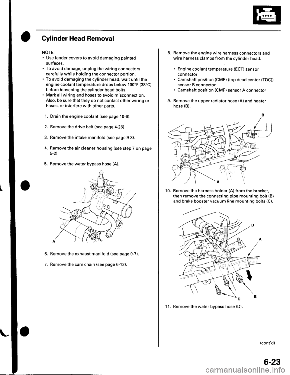
5. Remove the water bypass hose (A).
Remove the exhaust manifold (see page 9-7
Remove the cam chain (see page 6-12).
6.
7.
).
8. Remove the engine wire harness connectors and
wire harness clamps from the cylinder head.
. Engine coolant temperature (ECT) sensor
conneclor. Camshaft position (Cl\4P) (top dead center (TDC))
sensor B connector. Camshaft posilion (CMP) sensor A connector
9. Remove the upper radiator hose (A) and heater
hose (B).
'10. Remove the harness holder (A)from the bracket,
then remove the connecting pipe mounting boh {B)
and brake booster vacuum line mounting bolts {C).
(cont'd)
1 1. Remove the water bvpass hose (D).
6-23
Page 186 of 1139
Intake Manifold and Exhaust System
Intake Manifold Removal and Installation (cont'dl
5. Be prepared to catch and clean up spilled coolant.
Remove the water bypass hoses, then plug the
water bypass hoses.
6. Relievefuel pressure (see page 11-'144).
7. Remove the fuel line (seepagell-149).
8. Remove the positive crankcase ventilation (PCV)
hose (A), harness holder mounting bolt (B) and
harness clamp mounting bolt (C).
9-4
\-
(
9.Remove the engine wire harness connectors and
wire harness clamps from the intake manifold.
. Four injector connectors. ldle air control (lAC) valve connector. Throttle position (TP) sensor connector. fvlanifold absolute pressure {lvlAP) sensor
connector. Evaporative emission (EVAP)canister purge
valve connector
Remove the bolt securing the intake manifold and
bracket.
'1 0.
11.Remove allthe intake manifold mounting bolts/
nuts.
Remove the two stud bolts (A), then remove the
intake manifold (B).
1'>
Page 268 of 1139

11. At the wire harness side, check for continuity
between TP sensor 3P connector terminal No, 2
and body ground.
TP SENSOR 3P CONNECTOR
1 1213
'PS
REO
Wire side ot Iemale terminals
ls thete continuity?
YES-Repair short in the wire between the ECM
{A15) and the TP sensor.ll
NO-Go to step 12.
Connect ECM connector terminal A15 to body
ground with a jumper wire.
ECM CONNECTOR A 131P)
1121345679
1011112tc68 19 t2021
2312428129130
,tf$,rr*, ] ;uueen wrne
Wire side oJ .female terminals
/BLKI
12.
13. At the wire harness side, check for continuity
between TP sensor 3P connector terminal No. 2
and body ground.
TP SENSOR 3P CONNECTOR
(RED/BLX}
Wire side of female terminals
ls there continuity?
YES-Update the ECM if it does not have the latest
software, or substitute a known-good ECM, then
recheck (see page 11-6). lf the symptom/indication
goes away with a known-good ECM, replace the
original ECM.I
NO- Repair open in the wire between the ECM
(A15) and the TP sensor.l
14. lvleasure voltage between ECM connector
terminals 410 and A20.
ECM CONNECTOB A 131P}
vcc2(YEL/8LU)
Wire side of female terminals
ls there about 5 V?
YES Repair open in the wire betlveen the ECM
(A20) and the TP sensor.I
NO Update the ECM if it does nor have the latest
software, or substilute a known-good ECM, then
recheck (see page 1 1-6). lf the symplom indication
goes away with a known-good ECM. replace lhe
original ECM.I
123
TPS
11-61
Page 269 of 1139

PGM-FI System
(
(
DTC Troubleshooting (cont'd)
DTC P0123: TP Sensor Circuit High Voltage
1. Turn the ignition switch oN (ll)
2. Check the throttle position with the scan tool.
ls there about 10% or 0.5 V when the throttle is
fully closed and about 90% or 4.5 V when the
throttle is f ully opened?
YES lntermittent failure. system is OK at this time.
Check for poor connections or loose terminals at
the TP sensor and at the ECM, I
NO Go to step 3.
3. Turn the ignition switch OFF.
4. Disconnect the TP sensor 3P connector.
5. Turn the ignition switch ON (ll).
6. At the wire harness side, measure voltage between
the TP sensor 3P connector terminals No. 1 and
No.3.
TP SENSOR 3P CONNECTOR
W;re side of female terminals
ls thete about 5 V?
YES-Replace the throttle body (the TP sensor is
not available separately). I
NO Go to step 7.
11-62
7. Measure voltage between ECM connector
terminals A10 and A20.
ECM CONNECTOR A 131PI
Wire side of female terminals
Is there about 5 V?
YES- Repair open in the wire between the ECM(A10) and the TP sensor. t
NO Update the ECM if it does not have the latest
soflware, or substitute a known-good ECM, then
recheck (see page 11-6). lf the symptom/indicationgoes away with a known-good ECM, replace the
original ECM.I
Page 284 of 1139

DTG P0325: Malfunction in Knock Sensor
Circu it
1. Reset the ECM (see page 11-4).
2. Start the engine. Hold the engine at 3,000 rpm with
no load (in neutral) until the radiator fan comes on,
then let it idle.
3. Hold the engine at 3,000-4,000 rpm for at least
60 seconds.
ls DTC P0325 indicated?
YES-Go to step 4.
NO Intermittent failure, system is OK at this time.
Check for poor connections or loose terminals at
the knock sensor and at the ECM.I
4. Turn the ignition switch OFF.
5. Disconnect the starter subharness 6P connector.
6. Check for continuity between ECM connector
terminal Ag and body ground.
ECM CONNECTOR A 131P)
Wire side of lemale terminals
ls there continuity?
YES-Repair short in the wire between the ECM(A9) and the starter subharness 6P connector.l
NO Go to step 7.
7. Connect staner subharness 6P connector terminal
No. 5 to body ground with a jumper wire.
8.
STARTER SUAHARNESS6P CONNECTOR
l1l213ll,/l5l6l._
KS IJUMPER|RED/BLU) IW|REI
Wire side of female terminals
Check for continuity between body ground and
ECM connector terminal A9.
9.
ECM CONNECTOR A {31PI
Wire side of female terminals
ls there continuity?
YES-Go to step 9.
NO Repair open in the wire between the ECM (A9)
and the starter subharness 6P connector.l
Check the starter subharness between the 6P
connector and the knock sensor for an open or
short. lf it's OK, substitute a known-good knock
sensor and recheck.
ls DTC P0325 indicated?
YES Update the ECM if it does not have the latest
software. or substitute a known-good ECM, then
recheck {see page '11-6). lf the sym ptomlindication
goes away with a known good ECM, replace the
original ECM.I
NO Replace the original knock sensor and/or
sta rte r subharness.l
11-77
Page 346 of 1139

ECM ldle Learn Procedure
The idle learn procedure must be done so the ECM can
learn the engine idle characteristics.
Do the idle learn procedure whenever you do any of
these actions:. Disconnect the battery.
Replace the ECM or disconnect its connector.
Reset the ECM.
NOTE: Erasing DTCS with the Honda PGM Tester
does not require you to do the idle learn procedure.
Remove the No.6 ECU {ECM) ( 15A) fuse from the
under-hood fuse/relay box.
Remove the No.19 baftery (80A) fuse from the under-
hood fuse/relay box.
Remove PGM-FI main relay 1.
Remove any of the wires from the under-hood fuse/
retay Dox.
Disconnect any of the connectors from the under
hood fuse/relay box.
Disconnect the connector between the engine
compartment wire harness and ECM wire harness.
Disconnect the G2 terminal from the transmission
ho u srng.
Disconnectthe G'l terminal from the body.
Disconnectthe G101 terminal from the cylinder head
cover.
Procedure:
To complete the idle learn procedure, do this:
1. Make sure all electrical items (Ay'C, audio, rear
defogger, l:ghts, etc.,) are off.
2. Start the engine, and hold it at 3,000 rpm with no
load {in neutral) until the radiator fan comes on, or
until the engine coolanttemperature reaches 194"F(90'c).
3. Let the engine idle for about 5 minutes with the
throttle fully closed.
NOTE: lf the radiator fan comes on, do not include its
running time in the 5 minutes.
11-139
Page 359 of 1139
Fuel Supply System
{Fuel Pressure Regulator
Replacement
Remove the fuel pump (see page 1 1-153).
Remove the fuel pressure regulator (A).
Installthe part in the reverse order of removal witha new o-ring (B).
1.
2.
11-152
Fuel Filter Replacement
The fuel filter should be replaced whenever the fuelpressure drops belowthe specified value {270 320 kpa,2.8 3.3 kgf lcm', 40 47 psi), after making sure that thefuel pump and the fuel pressure regulator are OK.
1. Remove the fuel pump(seepagell-'153).
2. Remove the
Install in the reverse order of removalwith a new
base gasket (B) and a new o-ring (C), then check
these items:
' When connecting the wire harness, make sure
the connection is secure and the terminal (D) is
firmly locked into place.. When installing the fuel gauge sending unit iE),make sure the connection is secure and the
connector is firmly locked into place. Be carefulnot to bend or twist it excessively.
\
fuel filter (A).
@-to
ReIJ
e"^AR^ ...\e @n-)
gs
sg
Page 360 of 1139

Fuel Pump/Fuel Gauge Sending Unit Replacement
SpecialTools Required
Fuel sender wrench 07XAA-001010A
1.Relieve the fuel pressure (see page 11-144).
Remove the fuel fill cap.
Remove the seat cushion (see page 20-80).
Remove the access panel (A)from the floor.
5.
7.
Disconnect the fuel pump 5P connector (B).
Disconnect the quick-connect fitting {C) from the
fuel tank unit.
Using the special tool, loosen the fuel tank unit
locknut (A).
93 N.m19.5 kgf.m,69 lbf.ftl
11-153
8. Remove the locknut (A) andthefuel tankunit.
9. Remove the stopper {O). Release the hook (P) and
remove the fuel filter (B), the fuel gauge sending
unit (C). the case (D), the wire harness (E), and the
fuel pressure regulator (F).
10. When connecting the fuel tank unit, make sure the
connection is secure and the suction filter (G) is
firmly connected to the f uel pump (H).
11. Install the fuel tank unit in the reverse order of
removal with a new base gasket (l)and new o-rings
(J), then check these items:
. When connecting the wire harness, make sure
the connection is secure and the connector (K) is
firmly locked into the place.
. When installing the f uel gauge sending unit,
make sure the connection is secure and the
connector is firmly locked into place. Be careful
not to bend or twist the connector excessively.. When installing the fueltank unit, align the marks
(L) on the fuel tank (M) and the fuel tank unit (Ni