Page 569 of 1139
Front Suspension
Knuckle/Hub/Wheel Bearing Replacement
Exploded View
Check for delormationano oamage.
SPLASH GUARDCheck for corrosion. delormation.and damage.Replace if rusted.
WHEEL BEARINGReplace.
5 mm SCREWSReplace.FLAT SCREWS6x1.0mm9.8Nm(1.0 kgf.m,7.2 lbf.ft)
BRAKE DISC
SPINDLE NUT22 x 1.5 mm181 Nm(18.5 kgf.m, 134 lbt.ft)Replace.'--7.l'tq
IAppy a small amount of engine oilto the seating surface.
lcont'd)
SNAP RING
KNUCKLE
18-11
Page 570 of 1139

Front Suspension
Knuckle/Hub/Wheel Bearing Replacement {cont'dl
Special Tools Required. Hub dis/assembly tool 07GAF-SE00100. Balljoint remover,2S mm 0TlvlAC-S100200. Attachment 62 x 68 mm 07746-0010500. Driver 07749-0010000. SuDDort base 07965-5D90'100
1. Raise the front of the vehicle, and support it with
safety stands in the proper location (see page 1-8).
2. Remove the wheel cap, wheel nuts, and front wheel.
3. Remove the brake hose bracket mounting bolt (A).
108 N.m(11.0 kgf m,80 rbf.ftl
A8 x 1.25 mm22N.m12.2ksl.m,26 tbf.ftl
B12 x 1.25 mm108 N.m{11.0 kgf.m,80 rbf.ftl
4.Remove the caliper bracket mounting bolts (B), and
remove the caliper assembly (C) from the knuckle.
To prevent damage to the caliper assembly or
brake hose, use a short piece of wire to hang the
caliper assembly from the undercarriage. Do not
twist the brake hose with force.
18-12
5. Raise the stake (A), and remove the spindle nut (B).
-B
' 22x1.5mm, 181 N.m('18.s kgf.m,134 tbt.ft)
6. Remove the brake disc retaining flat screws (A).
A6x1.0mm9.8 N.m{1.0 kgt.m,7.2 tbl.ttl
7. Screw two 8 x 1.25 mm bolts (B) into the disc to
oush it awav from the hub. Turn each bolt two turns
at a time to prevent cocking the disc excessively,
\
\
Page 572 of 1139
Front Suspension
Knuckle/Hub/Wheel Bearing Replacement (cont'd)
14. Separate the hub (A)from the knuckle (B) using the
special tool and a hydraulic press. Be careful notto
deform the splash guard. Hold onto the hub to keep
it from falling when pressed clear.
./ .-''- .|
a'\s
Press the wheel bearing inner race (A) off of the
hub (B) using the speiialtool, a commercially
available bearing separator (C), and a press.
15.
07GAF-SE00100
Press
07GAF-SE00100
18-14
16. Remove the snap ring (A) and the splash guard (B)
from the knuckle (C).
Press the wheel bearing (A) out of the knuckle (B
using the special tool and a press.
11.
Pross
+
\
Page 573 of 1139

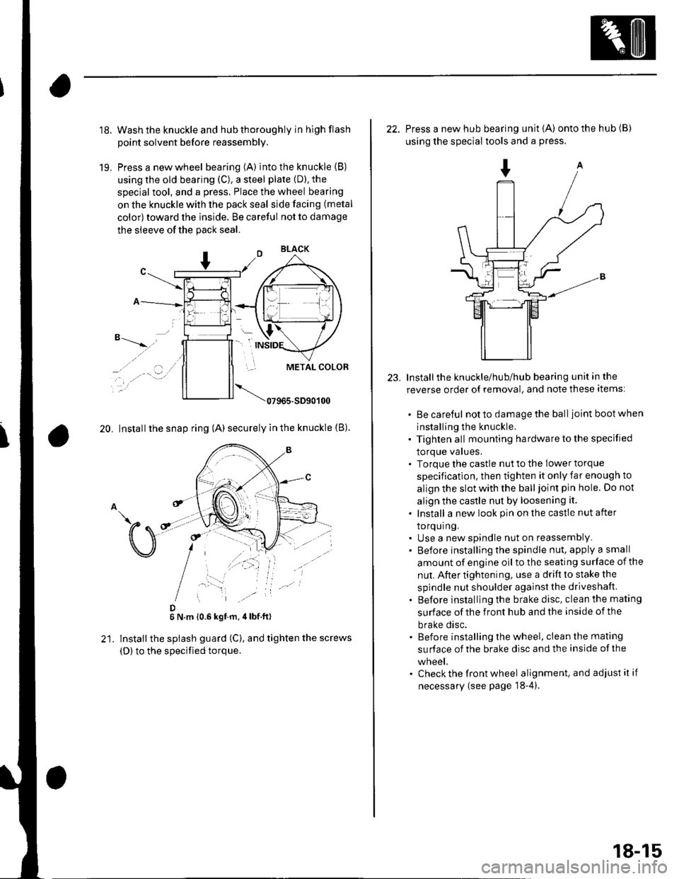
18.
19.
Wash the knuckle and hub thoroughly in hlgh flash
point solvent before reassembly.
Press a new wheel bearing (A) into the knuckle (B)
using the old bearing (C), a steel plate {D). the
special tool, and a press. Place the wheel bearing
on the knuckle with the pack seal side facing (metal
color) toward the inside. Be careful not to damage
the sleeve of the pack seal.
"-t-_"*,,''
_, .' . . a-�.) ../
..-.
20. Install the snap ring (A) securely in the knuckle (B).
D6 N.m 10.6 kgf.m,4lbf ft)
lnstall the splash guard (C), and tighten the screws
(D) to the specified torque.
23.
22. Press a new hub bearing unit {A) ontothehub(B)
using the special tools and a press.
Installthe knuckle/hub/hub bearing unit in the
reverse order of removal, and note these items:
. Be careful notto damagethe balljoint bootwhen
installing the knuckle.. Tighten all mounting hardware to the specified
lOrque values.. Torque the castle nut to the lower torque
specification, then tighten it only far enough to
align the slot with the ball joint pin hole. Do not
align the castle nut by loosening it.
. Install a new look pin on the castle nut after
torquing.. Use a new spindle nut on reassembly.. Before installing the spindle nut, apply a small
amount of engine oil to the seating surface of the
nut. After tightening, use a drift to stake the
spindle nut shoulder against the driveshaft.
. Before installlng the brake disc, clean the mating
surface of the front hub and the inside of the
brake disc.. Before installing the wheel, clean the mating
su rface of the brake disc and the inside of the
wneet.. Check the front wheel alignment, and adjust it if
necessary (see page 18-4).
18-15
Page 586 of 1139

Rear Suspension
Hub Bearing Unit Replacement
(cont'd)
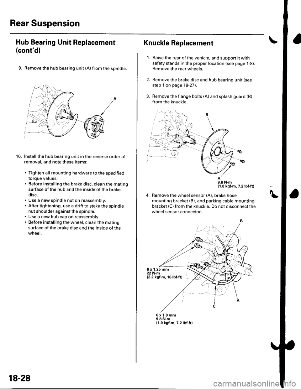
9. Remove the hub bearing unit (A) from the spindle.
Install the hub bearing unit in the reverse order of
removal, and note these items:
. Tighten all mounting hardware to the specified
torque values,. Before installing the brake disc, clean the mating
surface ot the hub and the inside of the brake
disc.. Use a new spindle nut on reassembly.. After tightening, use a drift to stake the spindle
nut shoulder against the spindle.. Use a new hub cap on reassembly.. Before installing the wheel, clean the mating
surface of the brake disc and the inside of the
wneel.
10.
,=,,,
18-28
Raise the rear of the vehicle, and suppon it with
safety stands in the proper location (see page 1-8).
Remove the rear wheels.
Remove the brake disc and hub bearing unit (see
step 1 on page 18-27).
Remove the flange bolts (A) and splash guard (B)
from the knuckle.
11.0 kgf.m, 7.2 lbf ft)
4. Remove the wheel sensor(A), braKe nose
mounting bracket (B), and parking cable mounting
bracket (C) from the knuckle. Do not disconnect the
wheel sensor connector.
8 x 1.25 mm22 N.m{2.2 kgf m, 16 lbf ftl
Knuckle Replacement
1.
6x1.0mm9.8 N,m{I.0 kgt.m,7.2 lbf ft)
tt
Page 1139 of 1139

SuspensionAdjustment................-............................184 VComponent Location Index................. 20-17
Windshield GlessReplacement............-..............-............. 20 19
Synchro Ring, Triple-coneInspection...............-..........................1339 ValveGuides
Synchro SleeveInspectaon/Reassemb1y ....................... 13 39
Inspection ............-.-................................ 6 32Beplacement ..........-................................ 6 33 Wiper Intermittent Control Unit,Rear WindowInput Test
T
Valve SeatsRepair ...................................................... 6 35.....22-134
WiDer Motor, Rear WindowRep1acement....................................... 22-1 46Adjustment .-.-.......Removal ...-...-......................................-... 6-31 WiDer Motor, windshield6-9
.....6-32 Test.......-..........-.....-.............................22-143Taillight
ThermostaiTest ........................
Inspec!on
Vehicle Speed Signal Circuit
VTC System
Wiper/WasheI
Wi.ing System
10 4 Troubleshooting .....-... ..........................22-65 Component Location In dex ..............22-134Replacement.....-...-....... ...................... 10 IvssThrottle BodyTest ..................Removal/lnstallation .. . . . . . .. ... 11-'165 VTC ActuatorDisassembly/Feassemb|y................-11-166 Inspection
Circuit Diagram .......................... 22-136, 131
Replacement -.............. ............ .............22 61 Wiper/Washor SwitchTesVReplacement .............................. 22-1 40
.................68 WireHarnesses
11-160
Replacement ........................................... 6 24 (Seefirstpageofthislndex)Throttle CableAdjustment ...... ...-.................... 11163 VTC Oil ConlrolSolenoid ValveRemoval/1nsta11ation..........................11164 Removal....-...-... |1-127 HowtoIn{ormation ...............................223Belay and Control UnitLocations .-....-.............. -.-.-....- 22-7, 4, 1 1, 12Beplacement.........-............................... 1767 ComponentLocationlndex.............. 11-117Tie-rod Ball Joint Boots
lnstallation
Replacement
Turn Signal/Hazard Relay
tsTiming/Cam ChainVTEC Solenoid Valve...612 Femoval/lnspection....-......................11-128................ 6 15
Timing/Cam Chain Auto-tensionelRemoval/1nsta11ation..............................6-19 W
Troubleshooting{See first page ot this Index)
Turn Signal Light
Timing/Cam Chain CaseOil SealInstallation......................-......................6,21 Washer Fluid Level SwitchTesVReplacement .............................. 22 1 44Trailing ArmsRemoval/lnstallation .............. . . . . ..... 18 33 Washer Fluid ReservoirReplacement ....................................... 22-1 46tnmComponent Location lndex ................- 20 49 Washer Motor, WindshieldRemoval/lnstallation ..-.......20 50,51,52,53 Test -..............-.............. ........................22 144
Washer Tube, WindshieldReplacement......-...-............................ 22 1 47
W.ter Outlet.........22 A4 Installation ..................-........................... '10-9
InputTest........22-87 lnstallation................ 10IWeter Passage
Wheels andTires
Turn Signal/Hazard Warning Lights Water PumpComponent Location In dex .................22 85 Inspection ........................... .. . . . ....... 10 5Circu it Diagram ................-................... 22-86 Replacement .-......................................... 10 5
U
WheelBearingsInspec|ion ....................................... ....... 18 8
Wheel Speed SensorsInspection ..-..,.,.,,.,,,,,.,.,,,...................... 19-59Replac€ment ........-....... . . . . . . .. -.... 19-59UndeFdash Fuse/R€lay BoxRemoval/lnstaf lation ............................ 22-49
Upper ArmsRemoval/|nsta11ation................. ... 18-32
],sInspect|on