Page 282 of 1139

32. fvleasure voltage between body ground and ECM
connector terminal (see table).
ECM CONNECTOR B (24P)
Wire side of female termrnals
ls there battery voltage?
YES-Go to step 33,
NO Go to step 41.
Turn the ignition switch OFF, and remove the
engine cover.
Disconnect the injector 2P connector from theproblem cylinder.
Measure the resistance between injector 2P
connector terminals No. 1 and No. 2.
INJECTOB 2P CONNECTOR
Terminal side of male terminals
ls there 10 Q 13A?
YES-Go to step 36.
NO Replace the injector (see page 1 1- 11 I ). t
33.
34.
35,
PROBLEM
CYLINDER
DTCEC t\4
TERMINAL
WIRE
COLOR
No. 1P0301B5BRN
No.2P0302B4RED
No.3P0303B3BLU
No.4P0304YEL
36.Exchange the injector from the problem cylinder
with one from another cylinder.
Letthe engine idle for 2 minutes.
Test-drive the vehicle for several minutes in the
range oI the lreeze data or under various
condilions if there was no freeze data.
Check for a DTC or Temporary DTC with the scan
tool.
ls DTC or Temporary DTC P0301, P0302, P0303,
or P0304 indicated?
YES Go to step 40.
NO Intermittent misfire due to injector
malfunction, etc. Make sure the injector
connections are secure. Check for poor connections
or loose terminals at the injector connector.l
Determine which cylinder{s} had the misfire.
Does the mislirc occur in the cylinder whete the
i nj ector w as exchanged ?
YES Replace the faulty injector.l
NO Update the ECM if it does not have the latest
software, or substitute a known-good ECM. then
recheck (see page 1 'l-6). lf the symptom/indication
goes away with a known-good EClvl, replace the
original ECM.I
Turn the ignition switch OFF.
Remove the engine cover.
Disconnect the injector 2P connector from the
problem cylinder.
44. Turn the ignition switch ON (ll)
37.
38.
39.
41.
42.
43.
(cont'd)
11-75
Page 284 of 1139

DTG P0325: Malfunction in Knock Sensor
Circu it
1. Reset the ECM (see page 11-4).
2. Start the engine. Hold the engine at 3,000 rpm with
no load (in neutral) until the radiator fan comes on,
then let it idle.
3. Hold the engine at 3,000-4,000 rpm for at least
60 seconds.
ls DTC P0325 indicated?
YES-Go to step 4.
NO Intermittent failure, system is OK at this time.
Check for poor connections or loose terminals at
the knock sensor and at the ECM.I
4. Turn the ignition switch OFF.
5. Disconnect the starter subharness 6P connector.
6. Check for continuity between ECM connector
terminal Ag and body ground.
ECM CONNECTOR A 131P)
Wire side of lemale terminals
ls there continuity?
YES-Repair short in the wire between the ECM(A9) and the starter subharness 6P connector.l
NO Go to step 7.
7. Connect staner subharness 6P connector terminal
No. 5 to body ground with a jumper wire.
8.
STARTER SUAHARNESS6P CONNECTOR
l1l213ll,/l5l6l._
KS IJUMPER|RED/BLU) IW|REI
Wire side of female terminals
Check for continuity between body ground and
ECM connector terminal A9.
9.
ECM CONNECTOR A {31PI
Wire side of female terminals
ls there continuity?
YES-Go to step 9.
NO Repair open in the wire between the ECM (A9)
and the starter subharness 6P connector.l
Check the starter subharness between the 6P
connector and the knock sensor for an open or
short. lf it's OK, substitute a known-good knock
sensor and recheck.
ls DTC P0325 indicated?
YES Update the ECM if it does not have the latest
software. or substitute a known-good ECM, then
recheck {see page '11-6). lf the sym ptomlindication
goes away with a known good ECM, replace the
original ECM.I
NO Replace the original knock sensor and/or
sta rte r subharness.l
11-77
Page 285 of 1139

PGM-FI System
a
a
DTC Troubleshooting (cont'd)
DTC P0335: CKP Sensor No Signal
DTC P0336: CKP Sensor Intermittent
Interruption
'1. Reset the ECM (see page 1 '1-4).
2. Sta rt the engine.
ls DTC P0335 and/or P0336 indicated?
YES Go to step 3.
NO Intermittent failure, system is OK at this time.
Check for poor connections or loose terminals at
the CKP sensor and at the ECM.I
3. Turn the ignition switch OFF.
4. Disconnect the CKP sensor 3P connector.
5. Turn the ignition switch ON {ll).
6. Measure voltage between CKP sensor 3P connector
terminal No.3 and body ground.
CKP SENSOR 3P CONNECTOF
(YEL/BLK}
Wire sade of female terminals
Is there battery voltage?
YES- Go to step 7.
NO Repair open ln the wire between PGM-Fl main
relay 1 and the CKP sensor.!
IGP
123
11-78
7. Measure voltage between CKP sensor 3P connector
terminal No, 1 and body ground
CKP SENSOR 3P CONNECTOR
Wire side of female tef minals
ls there about 5 V?
YES Go to step L
NO Go to step 10.
8. Measure voltage between CKP sensor 3P connector
terminals No.2 and No. 3.
CKP SENSOR 3PCONNECTOR
,llYtLL"l
(LGl{BRN/YELI
Wire side of female terminals
ls there battery voltage?
YES Go to step 9.
NO Repair open in the wire between the CKP
sensor and G 101 .I
9. Substitute a known-good CKP sensor and recheck.
ls DTC P0335 and/or P0336 indicated?
YES Update the ECM if it does not have the latest
software. or substitute a known good ECM, then
recheck {see page 1 1-6). lf the symptom/indication
goes away with a known-good ECM, replace the
original ECM.I
NO Replace the original CKP sensor.l
Page 290 of 1139

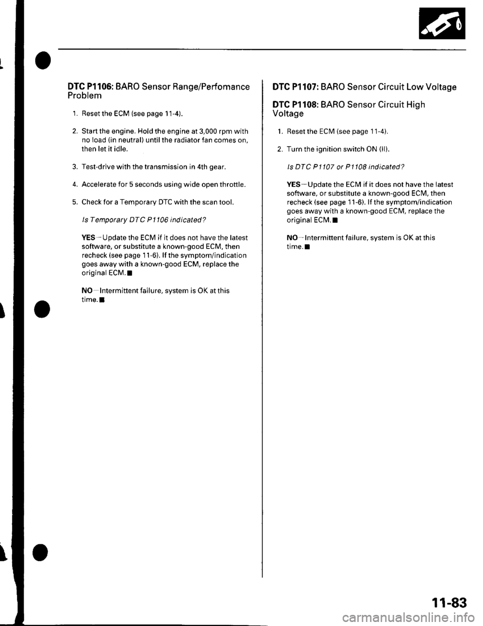
DTG Pl106: BARO Sensor Range/Perfomance
Problem
1. Reset the ECM (see page 11-4).
2. Start the engine. Hold the engine at 3,000 rpm with
no load (in neutral) until the radiator fan comes on,
then let it idle.
Test-drive with the transmission in 4th gear.
Accelerate for 5 seconds using wide open throttle.
Check for a Temporary DTC with the scan tool.
Is Temporary DTC Pl106 indicated?
YES-Update the ECM if it does not have the latest
software, or substitute a known-good ECM. then
recheck (see page 11-6). lf the symptom/indication
goes away with a known-good ECM, replace the
original ECM. !
NO Intermittent failure, system is OK at this
time.I
DTC Pl107: BARO Sensor Circuit Low Voltage
DTC Pl108: BARO Sensor Circuit High
Voltage
1. Reset the ECM {see page 1 1-4).
2. Turn the ignition switch ON (ll).
ls DTC P1107 or P1108 indicated?
YES-Update the ECM if it does not have the iatest
software, or substitute a known-good ECI\4, then
recheck (see page 11-6). lf the symptom/indication
goes away with a known-good ECM, replace the
original ECI\4.I
NO- Intermittent failure, system is OK at this
trme.l
11-83
Page 291 of 1139

PGM-FI System
(
(
DTG Troubleshooting (cont'dl
DTC Pl157: Ay'F Sensor (Sensor 1) Range/
Performance Problem
1. Resetthe ECIM (see page 11-4).
2. Start the engine.
ls DTC Pl157 indicated?
YES-Go to step 3.
NO Intermittent failure, system is OK at this time.
Check for poor connections or loose terminals at
the Ay'F sensor (Sensor 1 ) and at the ECN4.I
Turn the ignition switch OFF.
Disconnect the Ay'F sensor (Sensor 1) 4P connector
and ECM connector A (31P).
Connect A,/F sensor (Sensor 1) 4P connector
terminals No. 1 and No. 2 with a jumper wire.
A/F SENSOR (SENSOR 1) 4P CONNECTOR
AFS+ {BLU)
Wire side of female terminals
3.
JUMPER WIRE
11-84
L
6. Check for continuity between ECM connector
terminals 46 and A16.
ECM CONNECTOR A {3IP)
Wire side of female terminals
ls there continuity?
YES Go to step 9.
NO Go to step 7.
Connect A/F sensor (Sensor 1) 4P connecror
terminal No. 1 to body ground with a jumper wire.
A/F SENSOR {SENSOR 1I 4P CONNECTOR
7.
Wire side ot female terminals
Page 292 of 1139

8. Check for continuity between ECM connector
terminals 46 and body ground.
ECM CONNECTOR A 131P}
Wire side ol lemale terminals
ls there continuity?
YES-Repair open in the wire between the Ay'F
sensor (Sensor 1) and the ECM (416).1
NO-Repair open in the wire between the Ay'F
sensor (Sensor 1) and the ECM (46).1
Substitute a known-good Ay'F sensor (Sensor 1) and
recheck.
ls DTC P1157 indicated?
YES- Update the ECM if it does not have the latest
software, or substitute a known-good ECM, then
recheck (see page 1 1-6). if the symptom/indication
goes away with a known-good ECM, replace the
original ECM. !
NO- Replace the Ay'F sensor {Sensor 1). !
9.
DTC Pl158: Ay'F Sensor (Sensor 1) AFS -
Terminal Low Voltage
1. Resetthe ECM (see page 11-4).
2. Start the engine.
ls DTC P1158 indicated?
YES Go to step 3.
NO-lntermittent failure, system is OK at this time
Check for poor connections or loose termanals at
the Ay'F sensor (Sensor 1) and at the ECIM I
3. Turn the ignition switch OFF.
4, Disconnectthe Ay'F sensor (Sensor 1) 4P connector,
and ECM connector A (31P).
5. Check for continuity between ECM connector
terminal 416 and body ground.
ECM CONNECTOR A (31P)
ls thete continuity?
YES-Repair shon in the wire between the A,/F
sensor (Sensor 1)and the ECM (A16).1
NO Go to step 6.
'cont d)
Wire side oJ female terminals
11-85
Page 293 of 1139

PGM-FI System
(
a
DTC Troubleshooting (cont'd)
6. Substitute a known-good Ay'F sensor (Sensor 1)and
recheck.
Is DTC P1158 ind icated?
YES Update the ECM if it does not have the latest
software, or substitute a known-good ECM, then
recheck (see page 1 1-6). if the symptom/indication
goes away with a known-good ECM, replace the
original ECM.I
NO- Replace the Ay'F sensor (Sensor 1). t
11-86
DTC Pl159: A,/F Sensor (Sensor 1) AFS +
Terminal Low Voltage
1. Resetthe ECM (see page 11-4).
2. Sta rt the engine.
ls DTC P1159 ind icated?
YES-Go to step 3.
NO-lntermiftent failure. system is OK at this time.
Check for poor connections or loose terminais at
the A,/F sensor (Sensor 1) and at the ECM.I
3. Turn the ignition switch OFF.
4. Disconnect the Ay'F sensor (Sensor 1) 4P connector
and EcM connector A (31P).
5. Check for continuity between ECM connector
terminal 46 and body ground.
ECM CONNECTOR A {31PI
Wire side of female terminals
ls there continuity?
YES-Repair short in the wire between the Ay'F
sensor (Sensor 1) and the ECM (AO).I
NO Go to step 6.
Page 295 of 1139

PGM-FI System
DTC Troubleshooting (cont'dl
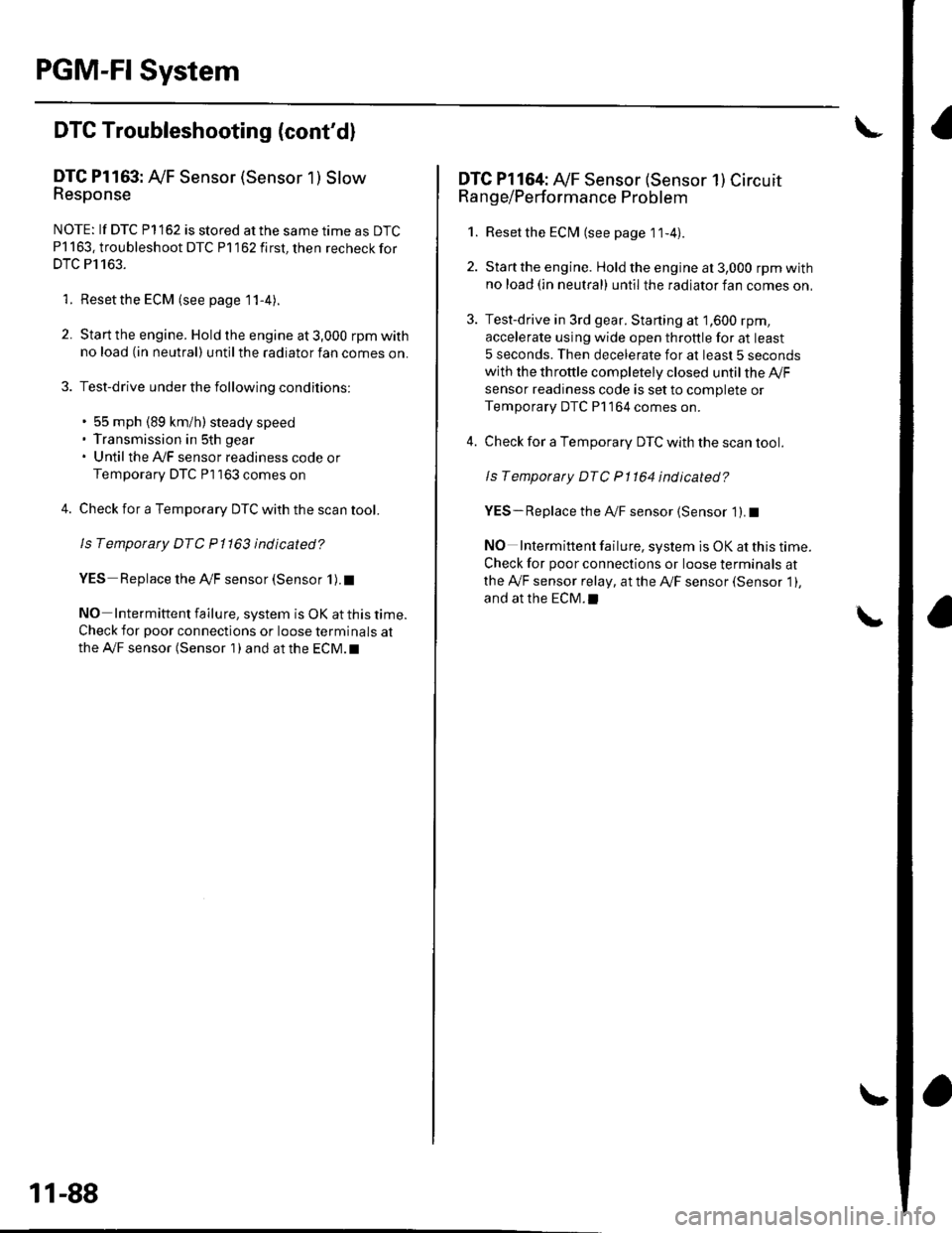
DTC Pl163: Ay'F Sensor (Sensor 1 ) SlowResponse
NOTE: lf DTC P1162 is stored at the same time as DTC
P1163. troubleshoot DTC P1162 first, then recheckfor
DTC P1163.
1. Reset the ECM (see page 1 1-4).
2. Start the engine. Hold the engine at 3,000 rpm with
no load (in neutral) until the radiator fan comes on.
3. Test-drive under the following conditions:
. 55 mph (89 km/h) steady speed' Transmission in sth gear' Until the Ay'F sensor readiness code or
Temporary DTC Pl163 comes on
4. Check for a Temporary DTC with the scan tool.
ls Temporary DTC P 1163 indicated?
YES Replace the Ay'F sensor (Sensor 1).I
NO Intermittent failu re, system is OK at this time.
Check for poor connections or loose terminals at
the A'lF sensor (Sensor 1 ) and at the ECM. t
11-88
DTC Pl164: A,/F Sensor (Sensor 1) Circuit
Range/Performance Problem
1. Resetthe ECI\4 (see page 1t-4).
2. Start the engine. Holdtheengineat3,000 rpmwith
no load (in neutral) until the radiator fan comes on,
3. Test-drive in 3rd gear. Starting at 1,600 rpm,
accelerate using wide open throttle for at least
5 seconds. Then decelerate for at least 5 seconds
with the throttle completely closed until the A,/F
sensor readiness code is set to complete or
Temporary DTC P1 164 comes on.
4. Check for a Temporary DTC with the scan tool.
ls Temporary DTC P1164 indicated?
YES- Replace the A,,/F sensor (Sensor 1). I
NO Intermittent failure, system is OK at this time.
Check for poor connections or loose terminals at
the Ay'F sensor relay, at the Ay'F sensor (Sensor 1),
and at the EcM.l