2003 HONDA CIVIC v tec
[x] Cancel search: v tecPage 896 of 1139

IVehicle Speed Signal Circuit Troubleshooting
Special Tools Required:
Test Harness 07LAJ-PT3020A
Before testing, inspect the No. 4 (10A) and No. 10 (7.5A)
fuses in the under-dash fuse/relay box.
1. Disconnect the 3P connector from the vehicle
speed sensor (VSS) {A).
Connect the test harness only to the engine wire
harness.
Connect the RED test harness clip (B) to the positive
probe of an ohmmeter. Cover the white (C) and
green {D) test harness leads with protective tape (E).
Check for continuity between the RED test harness
clip and body ground,
ls there continuity?
YES Go to step 5.
NO Repair open in the BLK wire between the VSS
and G 101.I
3.
4.
5. Connect the WHT test harness cliD (B) to the
positive probe of a voltmeter, and connect the RED
test harness clip (C) to the negative probe.
Turn the ignition switch ON (ll).
le thara h2ltarv v^ltada?
YES-Go to step 7.
NO Repair open in the BLK,/YEL wire between the
VSS and the under-dash fuse/relay box.l
Disconnect the WHT test harness clip (B).
Connect the GRN test harness clip {D) to the
positive probe of a voltmeter.
Is there 5 V or more?
YES- Go to step 9.
NO Repair short or open in the BLUMHT or WHT/
GRN wire between the VSS and the cruise control
unit, or the ECM.I
(cont'd)
7.
8.
22-65
Page 931 of 1139

Audio System
Audio Unit Removal/lnstallation
NOTE:. Put on gloves to protect your hands.. Take care not to scratch the dashboard and relatedpa rts.
1. Make sure you have the anti-theft code for the radio,
then write down the frequencies for the radio's
preset buttons.
2. Remove the driver's dashboard lower cover (see
page 20-59).
3. Remove the two mounting bolts, then pull out the
center panel (A).
4.Disconnect the audio connector (B) and antenna
lead (C), heater control panel connectors (D) and
HAVC push switch assembly (E), then remove the
center panel.
22-100
!\,
7.
Remove the heater control panel (see page 21 38).
Remove the four mounting bolts and the audio unit
from the radio brackets.
Installthe audio unit in the reverse order of
removal, and note these items:
. Make sure the audio unit and A/C connectors areplugged in properly, and the antenna lead is
connected properly.. Enter the anti-theft code for the radio, then enter
the customer's radio station presets.
\v
I
Page 1012 of 1139
Seat Belts
Front Seat Belt Replacement
SRS comDonents are located in this area. Review the
SRS component locations (see page 23-13) and the
precautions and procedures (see page 23-14) in the SRS
section before performing repairs or service,
NOTE: Check the front seat belts for damage, and
replace them if necessary. Be careful not to damage
them during removal and installation.
Front Seat Belt
Make sure you have the anti-theft code for the radio,
then write down the frequencies for the preset
buttons.
Disconnect the negative cable from the battery, and
wait at least 3 minutes before beginning work.
Slide the front seat forward fully.
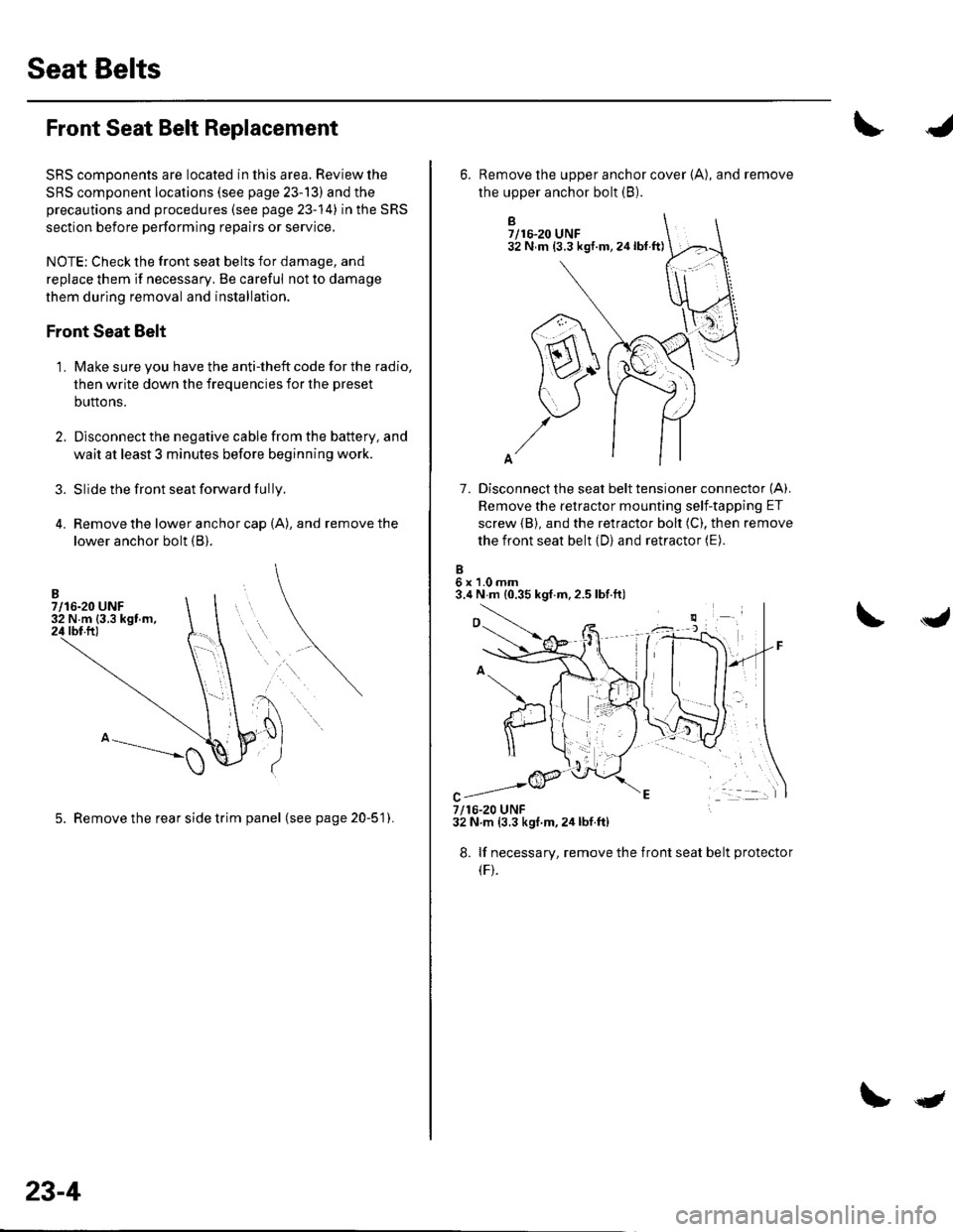
Remove the lower anchor cap (A), and remove the
lower anchor bolt (B).
3.
1.
5. Remove the rear side trim panel (seepage20-51).
23-4
qt
B7/16-20 UNF32 N m (3.3 kgf.m,24lbt.ft)
7. Disconnect the seat belt tensioner connector (A).
Remove the retractor mounting self-tapping ET
screw {B), and the retractor bolt (C), then remove
the front seat belt (D) and retractor (E).
6x1.0mm3.4 N m {0.35 kgf.m,2.5 lbf.ft)
6. Remove the upper anchor cover {A), and remove
the upper anchor bolt (B).
7/16-20 UNF32 N.m (3.3 kgf m,2ir lbf.ft)
8. lf necessary, remove the
(F).
front seat belt protecto
Page 1013 of 1139
9.
10.
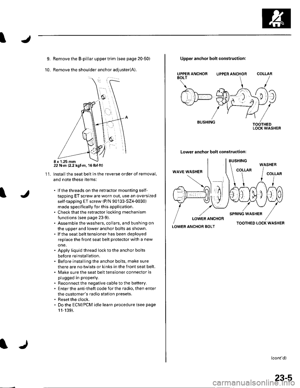
Remove the B-pillar upper trim {see page 20-50)
Remove the shoulder anchor adjuster{A).
22 N.m (2.2 kgf.m, 16lbf.ftl
Installthe seat belt in the reverse order of removal,
and note these items:
. lf thethreads on the retractor mounting self-
tapping ET screw are worn out, use an oversized
self-tapping ET screw (P/N 90133-SZ4-0030)
made specifically for this application.. Check that the retractor locking mechanism
functions (see page 23-9).. Assemble the washers, collars, and bushing on
the upper and lower anchor bolts as shown.. lf the seat belt tensioner has been deployed
replace the front seat belt protector with a new
one.. Apply liquid thread lock to the anchor bolts
before reinstallation.. Before installing the anchor bolts, make sure
there are no twists or kinks in the front seat belt.. Make sure the seat belt tensioner connector is
plugged in properly.
. Reconnect the negative cable to the battery.. Enter the anti-theft code for the radio, then enter
the customer's radio station presets.
. Reset the clock.. Do the ECM/PCM idle learn procedure {see page
11,139).
11.
8 x 1.25 mm
UPPER ANCHORBOLT
BUSHING
Upper anchor bolt construction:
UPPER ANCHOR
Lower anchor bolt construction:
COLLAR
TOOTHEDLOCK WASHER
LOWER ANCHOR BOLTTOOTHED LOCK WASHER
{cont'd)
WASHER
23-5
Page 1014 of 1139
Seat Belts
Front Seat Belt Replacement (cont'd)
Seat Belt Buckle
1. Make sure you have the anti-theft code for the radio,
then write down the frequencies for the preset
buttons.
2. Disconnect the negative cable from the battery ,and wait at least 3 minutes before beginning work.
3. Remove the front seat (see page 20-7'1).
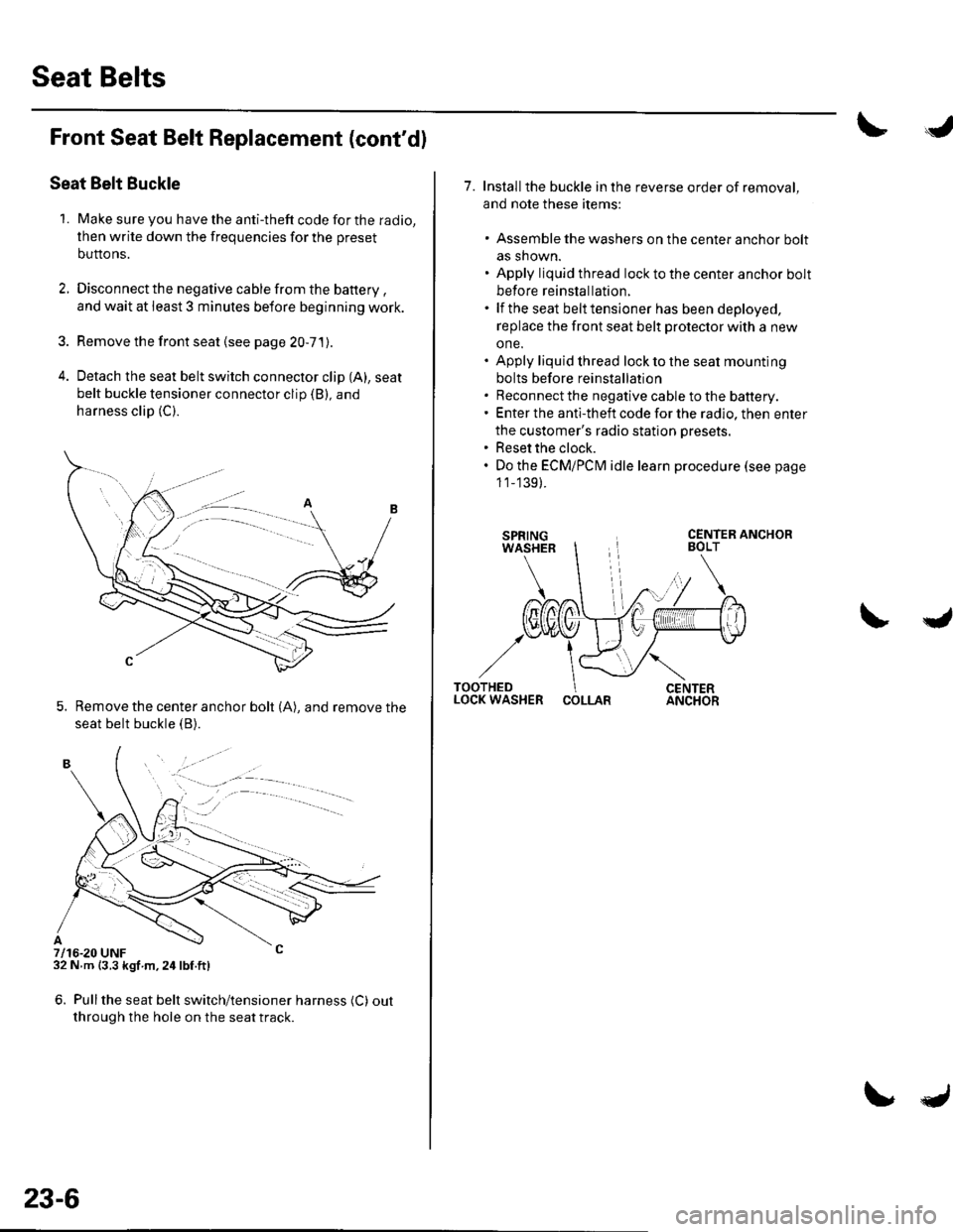
4. Detach the seat belt switch connector clip (A), seat
belt buckle tensioner connector clip (B), and
harness clip (C).
5. Remove the center anchor bolt (A), and remove the
seat belt buckle {B).
7/16-20 UNF32 N m {3.3 kgf m,24lbf.ft)
6. Pullthe seat belt switch/tensioner harness (C) out
through the hole on the seat track.
. -.. :.a--
23-6
7. Installthe buckle in the reverse order of removal,
and note these items:
. Assemble the washers on the center anchor bolt
as shown.. Apply liquid thread lock to the center anchor bolt
before reinstallation.. lf the seat belt tensioner has been deployed,
replace the front seat belt protector with a new
one.. Apply liquid thread lock to the seat mounting
bolts before reinstallation. Reconnect the negative cable to the battery.. Enter the anti-theft code for the radio, then enter
the customer's radio station presets.. Reset the clock.. Do the ECMiPCM idle learn procedure (see page
1 1_139).
COLLAR
Page 1021 of 1139
sRs
Precautions and Procedures
General Precautions
Please read the following precautions carefully beforeperforming airbag system service. Observe theinstructions described in this manual. or the airbags
could accidentally deploy and cause damage or injuries.
. Except when performing electrical inspections.
always turn the ignition switch OFF, disconnect the
negative cable from the battery, and wait at least 3minutes before beginning work.
NOTE: The memory is not erased even if the ignition
switch is turned OFF or the battery cables are
disconnected from the battery.. Use replacement pans which are manufactured to the
same standards and quality as the original parts. Do
not install used SRS parts from another vehicle. Useonly new pans when making SRS repairs.. Carefully inspect any SRS part before you install it.
Do not install any part that shows signs of being
dropped or improperly handled, such as dents, cracks,
or deformation.
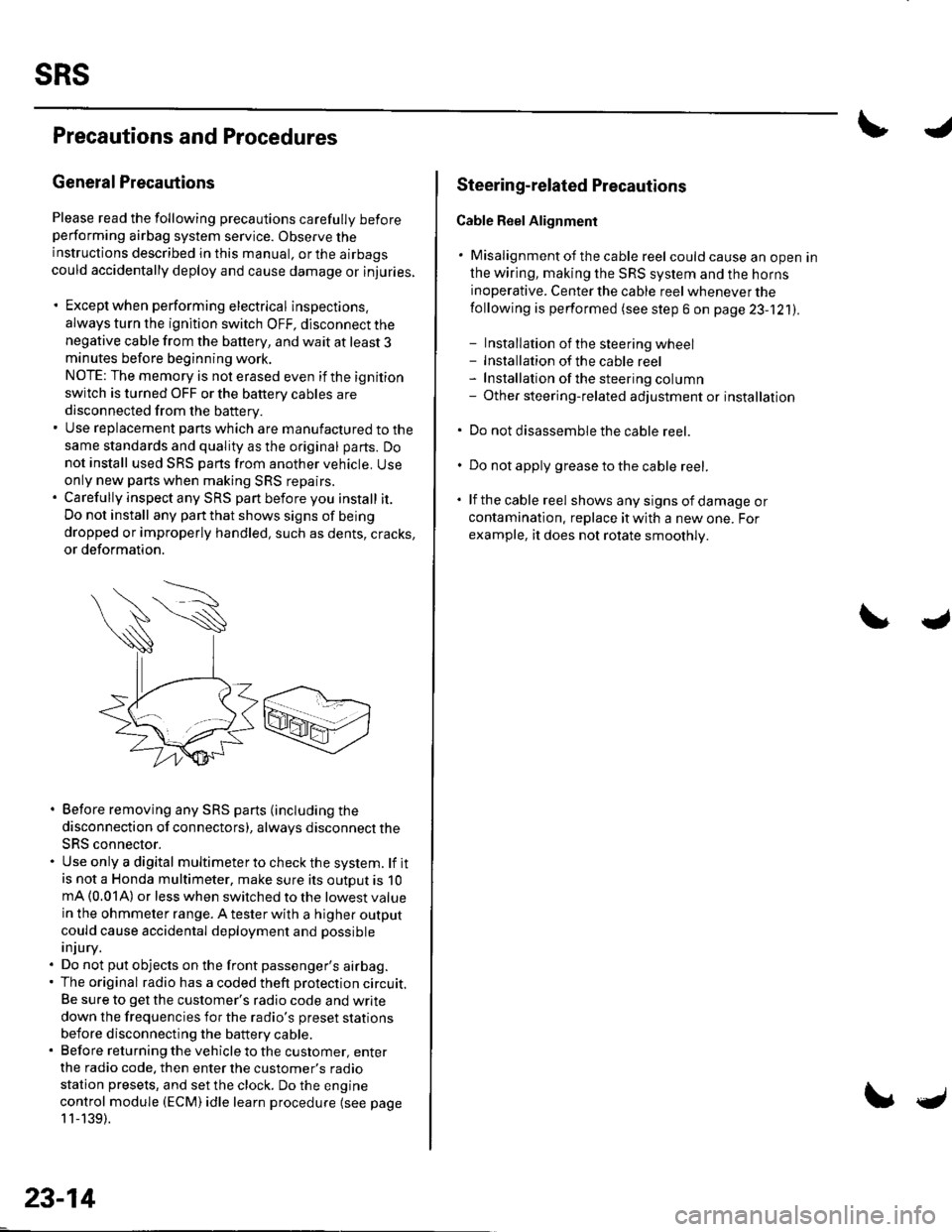
. Before removing any SRS parts (including the
disconnection of connectors), always disconnect the
SRS connector.. Use only a digital multimeter to check the system. lf itis not a Honda multimeter, make sure its outout is 10mA (0.01A) or less when switched to the lowest value
in the ohmmeter range. A tester with a higher output
could cause accidental deployment and possible
injury.. Do not put objects on the front passenger's airbag.. The original radio has a coded theft protection circuit.
Be sure to get the customer's radio code and write
down the frequencies for the radio's preset stations
before disconnecting the battery cable.. Before returning the vehicle to the customer, enter
the radio code. then enter the customer's radio
station presets, and set the clock. Do the engine
control module (ECM) idle learn procedure (see page
11-139).
23-14
c
Steering-related Plecautions
Cable Reel Alignment
. Misalignment of the cable reel could cause an open in
the wiring, making the SRS system and the horns
inoperative. Center the cable reel whenever the
following is performed (see step 6 on page 23-121).
- Installation of the steering wheel- Installation of the cable reel- Installation ofthe steering column- Other steering-related adjustment or installation
. Do not disassemble the cable reel.
. Do not apply grease to the cable reel.
. lf the cable reel shows any signs of damage or
contamination. replace it with a new one. For
example, it does not rotate smoothly.
Page 1034 of 1139
I
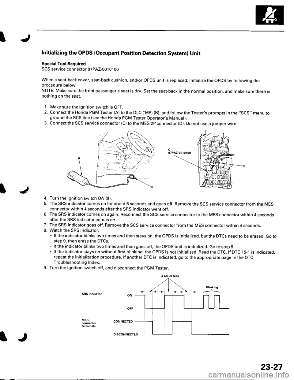
Initializing the OPDS {Occupant Position Detection System} Unit
Special Tool Required
SCS service connector 07PAz-00'1 01 00
When a seat-back cover, seat-back cushion, and/or OPDS unit is replaced, initialize the OPDS by following theprocedure below.
NOTE: Make sure the front passenger's seat is dry. Set the seat-back in the normal position, and make sure there isnothing on the seat.
'1. l\4ake sure the ignition switch is OFF.
2. Connect the Honda PGM Tester (A) to the DLC (16P) (B), andfollowtheTester's prompts jn the ,,SCS,, menu toground the SCS line (see the Honda PGM Tester Operator's ManuaD.
3. Connect the SCS service connector (C) to the MES 2P connector (D). Do not use a iumoer wire.
c07PAZ-00r0100
4. Turn the ignition switch ON {ll).
5. The SRS indicator comes on for about 6 seconds and goes off. Remove the SCS service connector from the MESconnector within 4 seconds after the SRS indicator went off.
6. The SRS indicator comes on again. Reconnect the SCS service connector to the MES connector within 4 secondsafter the SRS indicator comes on.
7. The SRS indicator goes off. Remove the SCS service connector from the MES connector withln 4 seconds.8. Watch the sRS indicator.'lftheindicatorblinkstwotimesandthenstayson,theOPDSisinitialized.buttheDTCSneedtobeerased.Goto
step 9, then erase the DTCS..lftheindicatorblinkstwotimesandthengoesoff,theOPDSunitisinitialized.Gotostep9.
' lf the indicator stays on without first blinking.the OPDS is not initialized. Readthe DTC. lf DTC 15-'l is indicated,repeat the initialization procedure. lf another DTC is indicated, go to the appropriate page in the DTCTroubleshooting Index.
9. Turn the ignition switch off, and disconnect the PGM Tester.
SBS indic.ror
MES
IJ
DISCONNECTED
23-27
Page 1035 of 1139
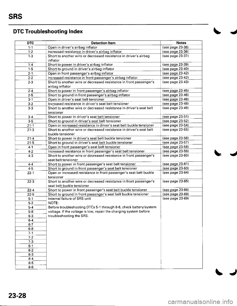
sRs
DTCDetection ltemNotes
t- |ODen in driver's airbaq inflator(see Daqe 23-36)
Increased resistance in driver's airbaq inflator(see Daoe 23-36
t-5Shon to another wire or decreased resistance in driver's airbag
inflator
(see page 23-37)
1-4Shortto Dower in driver's airbao inflator(see paqe 23-39
t-5Shortto qround in driver's airbaq inflator{see paqe 23-40
2-1Open in front Dassenqer's airbaq inflator{see oaoe 23-42
2-2Increased resistance in front passenqer's airbaq intlator(see oaqe 23-42
2-3Short to another wire or decreased resistance in front passenger's
airbao inflator
(see page 23-43)
2-4Short to oower in front oassenoer's airbaq inflator(see paqe 23-45
2-5Short to qround in front passenqer's airbaq inflator(see paqe 23-46
3-1ODen in driver's seat belt tensioner(see page 23-48
3-2lncreased resistance in driver's seat belt tensioner(see paqe 23-48
3-3Short to another wire or decreased resistance in driver's seat belt
tensioner
(see page 23-49)
3-4Short to oower in driver's seat belt tensioner(see Daqe 23-51
3-5Short to oround in driver's seat belt tensioner(see oaoe 23-52
21-1ODen or increased resistance in driver's seat belt buckle tensioner(see paqe 23-54
Short to another wire or decreased resistance in driver's seat belt
buckle tensioner
(see page 23-55)
2't -4Short to Dower in driver's seat belt buckle tensioner(see paqe 23-56)
2't-5Shon to oround in driver's seat belt buckle tensioner(see oaqe 23'57
4-'lODen in front oassenoer's seat belt tensioner{see page 23-58)
4-2lncreased resistance in front oassenqer's seat belttensioner{see paqe 23-58)
4-3Short to another wire or decreased resistance in front passenger's
seat belt tensioner
{see page 23-60)
4-4Shon to Dower in front Dassenqer's seat belt tensionerlsee oaqe 23-61
4-5Short to qround in front oassenoer's seat belt tensioner(see Daqe 23-63
Open or increased resislance in front passenger's seat belt buckle
tens ioner
(see page 23-64)
22-3Short to another wire or decreased resistance in front passenger's
seat belt buckle tensioner
(see page 23-65)
22-4Short to oower in front oassenqer's seat belt buckle tensioner(see paqe 23-66
22-5Short to oround in front oassenoer's seat belt buckle tensioner(see paqe 23-68
5-1lnternal failure of SRS unit
NOTE:
Before troubleshooting DTCS 5-1 through 8-6, check battery/system
voltage. lf the voltage is low, repair the cha rging system before
troubleshootino the SRS.
(see page 23-69)
5-2
5-4
5-8
6-3
6-4
6-7
6-8
1-)
7-3
8-1
a-2
8-4
8-5
8-6
DTC Troubleshooting Indext.
tJ
23-28
\J