Page 8 of 1139
General Information
Warning/Caution Label Locations (cont'dl
SRS WARNINGLABEL
SERVICE INFORMATION LABEL(Undor-hood Emission ControlInformation lab€l) and ENGINECOOLANT INFORMATION
RADIATORCAP CAUTION
BATTERYCAUTION
1-6
t
TIRE INFORMATION
c
Page 18 of 1139
ItemMeasulementOualificationStandard or New Service LimitFuel pressure
regulator
Pressure with fuel pressure gauge
connected
320-370 kPa 13.3-'3.8 kgtcm', 47 52psi)
FueltankCapacity50 4 (13.2 US galiEngine idleldle speed with headlights and radiator
fan off
Neutral750 50 rpm
Fast idleNeutral1,600150 rpm
Standards and Service Limits
Fuel and Emissionsf
.\
ra
Clutch
ItemMea3urem€nlOualificationSlandard or NewService LimitClutch pedalHeight from the floor193 mm (7.60 in.)Stroke130 140 mm 15.1 5.5in.)
10 16 mm (0.39 0.63 in.)Disengagement height from the floor1'15 mm (4.53 in.) min.Bunout on clutch mating surface0.05 mm 10.002 in.) max.0.15 mm (0.006 in.)Clutch discBivet head depth1.65 2.25 mm (0.065 0.089 in.)0.7 mm {0.03 in.)Ihickness8.3 8.9 mm (0.33 0.35 in.)6.0 mm (0.24 in.)Pressure plateWarpage0.03 mm (0.001 in.)max.0.15 mm (0.001 in.)Height of diaphragm spring fingersMeasured with
specialtool and
feeler gauge
0.6 mm (0.02 in.) max.0.8 mm (0-03 in.)
2-6
\
Page 85 of 1139
18.
19.
Remove the drive belt (see page 4-26).
Remove the lvC line mounting bolt.
20. Remove the radiator cap.
21. Raise the hoist to full height.
22. Remove the front tires/wheels.
23. Remove the splash shield.
o@
24. Loosen the drain plug in the radiatorto drain the
engine coolant (see page 10-6).
25. Drain the transmission fluid (see page 13'3).
26. Drain the engine oil {see page 8-5).
27. Disconnect the stabilizer links (see page 18-18).
28. Disconnect the suspension lower arm ball joints
(see step 3 on page 18-19).
29. Remove the driveshafts {see page 16-3). Coat all
precision finished surfaces with clean engine oil.
Tie plastic bags over the driveshaft ends.
30. Disconnect the air fuel ratio {4,/F) sensor connector
(A) and secondary heated oxygen sensor
(secondary HO2S) connector (B), then remove the
three way catalytic converter {TWC) assembly {C).
31. Remove the lower hose.
(cont'd)
5-5
Page 191 of 1139

Engine Cooling
Cooling System
Component Location Index ......................................... 10-2
Radiator Cap Test ..................... .......... 10-3
RadiatorTest ............. 10-3
Fan Motor Test .......... l0-4
Thermostat Test ...................... ........... 10-4
Water Pump Inspection ..................... 10-5
Water Pump Replacement ................. 10-5
Coolant Check .............. ....................... 10-6
Coolant Replacement ......................... 10-6
Thermostat Replacement .................. 10-8
Water Passage Installation ................ 10-9
Water Outlet Installation .................... 10-9
Radiator and Fan Replacement ................................... 10-10
Fan Controls
Component Location Index ......................................... 10-11
Symptom Troubleshooting Index ............................... 10-12
Circuit Diagram ......... 10-13
Radiator Fan CircuitTroubleshooting ........................ 10-14
Radiator Fan Switch Circuit Troubleshooting
(Open) ............ ........ 10-16
Radiator Fan Switch Circuit Troubleshooting
(Short) ............ ........ 10-16
Radiator Fan Switch Test ................... 10-17
Radiator Fan Switch Reolacement .............................. 10-17
Page 192 of 1139
Cooling System
Component Location Index
WATER PUMPInspection, page 10-5Replacement. page 10-5
RESERVETANK
RADIATORCAP
RAOIATOR FAN SWITCHTest, page 10-17Replacement, page 10'17
\
WATER OUTLET,Installation, page'10-g
\f
CONNECTING PIPE
WATER PASSAGEInstallation, page 10-9
THERMOSTATTest, page 10 4Replacement, page 10 8
RADIATORReplacement, page 10-'l0
RADIATOR FANASSEMgLYReplacement, page 10-10Fan MotorTest, page 10 4A/C CONDENSERFAN ASSEMBLYReplacement, page 10 10Fan Motor Test, page '10-4
10-2
\J
Page 193 of 1139
Radiator Cap Test
1. Remove the radiator cap {A), wet its seal with
engine coolant, then install it on the pressure tester(B) (commercially available).
Apply a pressure of 93 '123 kPa {0.95 1.25
kgf/cm', l4 18 psi).
Check for a drop in pressure.
lf the pressure drops, replace the cap.
3.
4.
Radiator Test
Wait untilthe engine is cool, then carefully remove
the radiator cap and fill the radiator with engine
coolant to the top of the filler neck.
Attach the pressure tester (A) (commercially
available) to the radiator.
1.
3.
4.
Apply a pressure ot 93 '123 kPa (0.95 1 .25
kgf/cm', '14 18 psi).
Inspect for engine coolant leaks and a drop in
pressu re.
Remove the tester, and reinstall the radiator cap.
10-3
Page 196 of 1139
Cooling System
1 . Look at the coolant level in the reserve tank. Make
sure it is between the MAX mark (A) and MIN mark(B),
Goolant Check
lf the coolant level in the reserve tank is at or below
the MIN mark, add coolant to bring it up to the l\4AX
mark, and inspect the cooling system for leaks.
10-6
\-
Coolant Replacement
1.
\
Start the engine. Set the heater temperature control
dial to maximum heat. then turn off the ignition
switch. Make sure the engine and radiator are cool
to the touch.
Remove the radiator cap.
Remove the splash shield (see step 23 on page 5-5).
Loosen the drain plug (A), and drain the coolant.
Remove the reserve tank drain cap (A), and drain
the coolant.
\
Page 197 of 1139

1.
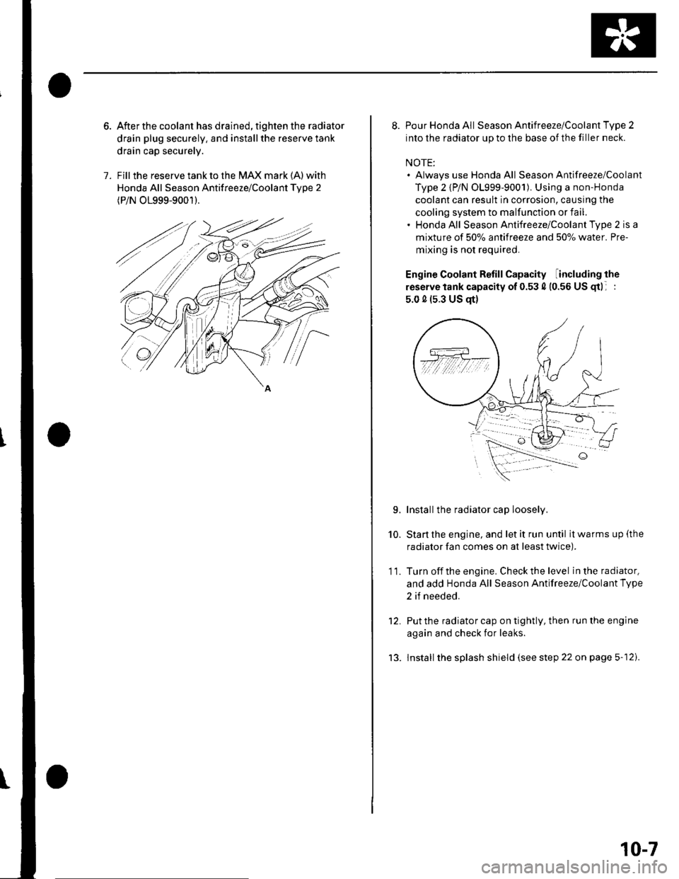
After the coolant has drained, tighten the radiator
drain plug securely. and installthe reserve tank
drain cap securely.
Fill the reserve tank to the MAX mark (A) with
Honda All Season Antifreeze/Coolant Tvpe 2
(P/N O1999-9001).
8. Pour Honda All Season Antifreeze/Coolant Type 2
into the radiator up to the base of the filler neck.
NOTE:. Always use Honda All Season Antifreeze/Coolant
Type 2 {P/N 01999-9001). Using a non-Honda
coolant can result in corrosion, causing the
cooling system to malfunction or fail.. Honda All Season Antifreeze/Coolant Type 2 is a
mixture of 50% antifreeze and 507o water. Pre-
mixing is not required.
Engine Coolant Refill Capacity including the
reserve tank capacity of 0.53 4 (0.56 US gtl :
5.0 0 (s.3 US qt)
Installthe radiator cap loosely.
Start the engine, and let it run until it warms up (the
radiator fan comes on at least twice).
Turn off the engine. Check the level in the radiator,
and add Honda All Season Antifreeze/Coolant Type
2 if needed.
Put the radiator cap on tightly, then run the engine
again and check for leaks.
lnstall the splash shield (see step 22 on page 5-12).
10.
11.
L
tJ.
10-7