2003 HONDA CIVIC 22-64
[x] Cancel search: 22-64Page 646 of 1139

ABS Components
DTC Troubleshooting (cont'd)
DTC 81: CPU (Central Processing Unit)
1. Clear the DTC, then disconnect the Honda PGM
Tester.
2. Test-drive the vehicle.
Does the ABS indicator come on and is DTC 81
indicated ?
YES Replace the ABS modulator-control unit.l
NO-The system is OK at this time. t
19-52
ABS Indicator Gircuit
Troubleshooting
ABS indicator does not come on
1. Turn the ignition switch ON (ll), and watch the ABS
indicator.
Does the ABS indicator come on?
YES The system is OK at this time.I
NO Go to step 2,
Pull up the parking brake lever.
Does the btake system indicator come on?
YES Go to step 3.
NO Repair open in the indicator power source
circuit. lf necassary, substitute a known-good ABS
modulator-control unit, and recheck. I. Blown No, 10 (7.5A) fuse.. Open in the wire between the No. 10 (7.5A)fuse
and lhe gauge assembly,. Open circuit inside the fuse box.
Turn the ignition switch OFF.
Disconnect the ABS control unit 31P connector.
Turn the ignition switch ON (ll).
Does the ABS indicator come on?
YES-Check for loose terminals in the ABS control
unit 31P connector. lf necessary, substitute a
known-good ABS modulator-control unit, and
recheck.l
NO Go to step 6.
Turn the ignition switch OFF.
Remove the gauge assembly (see page 22-64).
3.
5.
6.
7.
Page 722 of 1139

Dashboard
Dashboard Removal/lnstallation
(cont'd)
11. From outside the driver's door, remove the caps (A),
then remove the bolts (8, C, D), and lift up on the
dashboard (E) to release it from the guide pins
(F. G) on the body.
Fastener Locations
B>rBolt.3 C>: Bolt,2 D>: Bolt,2
m6[-,,,,",",,-,F6't---'' ffi'!--v{/- Kr* w-
B
$7:
^/761:
/,-,. r:; 8 x 1.25 mm22Nm(2.2 kgf.m, 16lbf.ft)
13.
{2.2 kgf m, 16lbf.ftl
Carefully remove the dashboard through the front
door opening.
lnstall the dashboard in the reverse order of
removal, and note these items:
. Make sure the dashboard fits onto the guide pins
correctly.. Apply liquid thread lock to the dashboard
mounting bolts of the middle portion before
reinstallation.. Before tightening the bolts, make sure each wire
harness and control cables are not pinched.
. Make sure the connectors are plugged in
properly, and the antenna lead is connected
propeny.. Reconnect the negative cable to the battery.. Enter the anti-theft code for the radio, then enter
the customer's radio station presets.
. Reset the clock.. Do the ECM/PCM idle learn procedure isee page
1 '1-139).
20-68
Steering Hanger Beam
Replacement
NOTE: Put on gloves to protect your hands.
1, Remove the dashboard (see page 20-66).
2. Remove these items from the dashboard:
. lnstrument panel (see page 20-59). Driver's pocket (see page 20-60). Gauge assembly (see page 22-64). Passenger's airbag (see page 23-'l 14)
Remove the screws, then remove the glove box
striker (A).
Fastenea Locations
):Screw,4
\
Page 831 of 1139

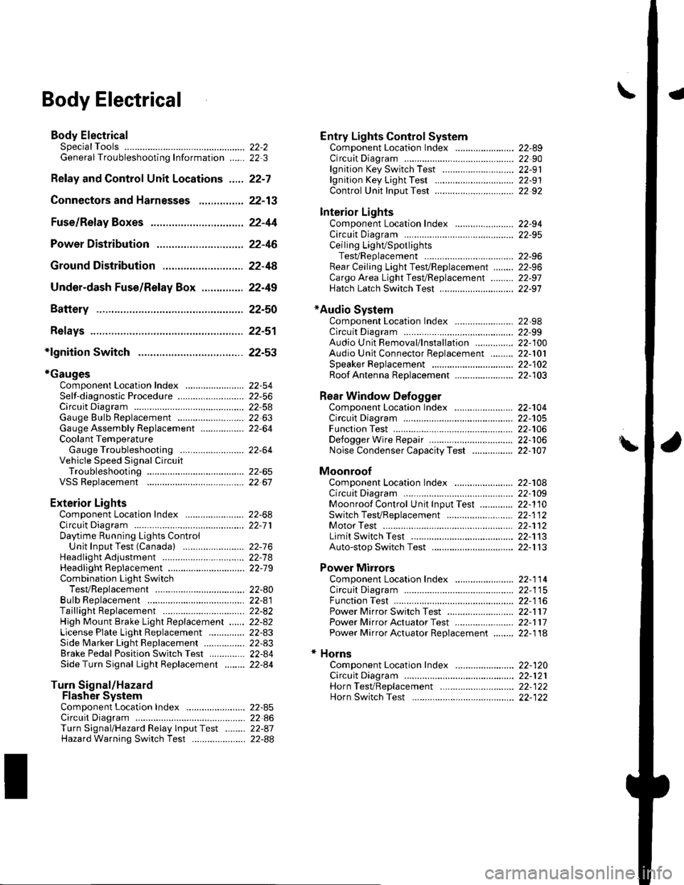
\Body Electrical
Body ElectricalSpecialToolsGeneral Troubleshooting tntorrnaiion.'......
Relay and Control Unit Locations .....
Connectors and Harnesses
Fuse/Relay Boxes ...............................
Power Distribution .............................
Ground Distribution ...........................
Under-dash Fuse/Relay Box ..............
Battery ..............
Relays ................
*lgnition Switch ..............
*Gauges
Component Location Index .......................Self-diagnostic Procedure ..........................Circuit DiagramGauge Bulb Replacement ..........................Gauge Assembly ReplacementCoolant Temperature
Gauge Troubleshooting .... ....................Vehicle Speed Signal CircuitTroubleshootingVSS Replacement
Exterior LightsComponent Location Index .......................Circuit DiagramDaytime Running Lights ControiUnit Input Test (Canada) ........................Headlight Ad,ustment .................. .. .....Headlighr Replacement ..............................Combination Light SwitchTest/ReplacementBulb ReplacementTaillight Replacement ..........................High Mount Brake Light Replacement ......License Plate Light Replacement ..............Side Marker Light Replacement ................Brake Pedal Position Switch Test ..............Side Turn Signal Light Replacement ........
Turn Signal/HazardFlasher SystemComponent Location Index .......................Circuit DiagramTurn Signal/Hazard Relay lnputTest ........Hazard Warning Switch Test
22,3
22-7
22-13
22-44
22-46
22-4A
22-49
22-50
22-51
22-53
22-5422-5622-5422 6322-64
22-64
22-6522 61
22-6822--71
22-7 622-7422-79
22-AO22-4122-8222-4222-4322-4322-4422-84
22-8�522 A622-8722-88
22-10422-105
22-10622-107
Entry Lights control systemComponent Location Index ....................... 22-89Circuit Diagram ......... 22 90lgnition Key Switch Test .....................,...... 22-9'llgnition Key Light Test ............................... 22-91Control Unit Input Test ..........,.................... 22 92
Interior LightsComponent Location Index ....................... 22-94Circuit Diagram ......... 22-95Ceiling LighVSpotlightsTesVReplacement ................................... 22-96Rear Ceiling Light TesVReplacem ent ........ 22-96Cargo Area Light Test/Replacem ent ......... 22-97Hatch Latch Switch Test ..,..,....................... 22-97
*Audio SystemComponent Location Index ....................... 22-98Circuit Diagram ......... 22,99Audio Unit Removal/lnstallation ............... 22-1OOAudio Unit Connector Replacement ......... 22-101Speaker Replacement ................................ 22-102Roof Antenna Rep1acement ....................-.. 22-103
Rear Window DefoggerComponent Location Index ...........Circuit Diasram .. ....... .. ..... ....... ...:::::.::.::.Function TestDefogger Wire Repair .................................Noise Condenser CapacityTest ................
MoonroofComponent Location Index ....................... 22-1OBCircuit Diagram ......... 22-109Moonroof Control Unit Input Test ............. 22-'l10Switch TesVReplacement ........,.....,........... 22-1 12Motor Test ................. 22-112Limit Swilch Test ...... 22-'l'13Auto-stop Switch Test ................................ 22-1 13
Power MirrorsComponent Location Index ....................... 22-114Circuit Diagram ......... 22-115Function Test ............. 22-116Power Mirror Switch Test .......................... 22-ll7Power Mirror Actuator Test ....................... 22-117Power Mirror Actuator Replacement ........ 22-11A
* HornsComponent Location Index ....................... 22-120Circuit Diagram ......... 22-121Horn TesVReplacement ...........................-. 22-122Horn Switch Test .,.... 22-122
\
Page 885 of 1139

Gauges
\-Component Location Index
PARKING BRAKE SWITCHpage 19-10
FUEL GAUGE SENDINGpage 11-156ENGINE OIL PRESSURE SWITCHpage 8-4
GAUGE ASSEMBLYSelJ-diaqnostic Procedure, page 22-56Gauqe dulb Replacement, page 22 63Rep6cement, page 22-64Coolant Temperature GaugeTroLrbleshooting, page 22'64
BRAKE FLUID LEVEL SWITCHpage 19-10VEHICLE SPEED SENSOR {VSS)Troubleshooting, page 22-65Beplacement, page 22-67
22-54
\
Page 895 of 1139

Gauges
2.
3.
Gauge Assembly Replacement
1.Remove the instrument panel (see page 20-59),
then remove the upper column cover {see page 17-
Place a clean shop towel (A) under the gauge
assembly to prevent scratching the steering
colum n or dash panel.
Remove the screws from the gauge assembly (B).
Disconnect the connectors (C), and remove thegauge assemDry.
Installthe gauge assembly in the reverse order of
removal.
Coolant Temperature Gauge
Troubleshooting
Before testing, check the No. I { 10A) fuse in the under-
hood fuse/relay box and the No. '10 (7.5A) fuse in the
under dash fuse/relay box.
1. Start the engine, and check the malfunction
indicator lamp (MlL).
Does the MIL come on?
YES- Troubleshoot the cause of the ECM DTC (see
page 1 1-57), and recheck.
NO-Go to step 2.
2. Check for a multiplex control unit DTC (see page
22,168).
ls a DTC ind icated?
YES Troubleshooting the cause of the multiplex
control unit DTC {see page 22-168), and recheck.
NO Go to step 3.
3. Do the communication line check with the self-
diagnosis procedure (see page 22-56).
ls the word "Error" indicated on the odo/ttip
d isplay ?
YES The gauge cannot receive the signal from the
multiplex control unit and the ECI\,4. Check for an
open in the WHT/GRN wire (gauge connector
terminal B 13). lf no open is found, go to step 5.
NO Go to step 4.
4. Do the gauge drive circuit check with the self-
diagnosis procedure (see page 22-56).
Does the temperature gauge needle sweep lrom
the minimum position to the maximum, then tetutn
to the minimum position?
YES Go to step 5.
NO Replace the gauge assembly.l
5. Substitute a known-good ECM and recheck.
Did the symptom/ ind ication go away?
YES Replace the ECM.
NO Substitute a known good gauge assembly. lf
the symptom/indication goes away, replace thegauge assembly.l
4.
22-64
Page 1108 of 1139

)
t5.
17.
18.
Turn the ignition switch OFF.
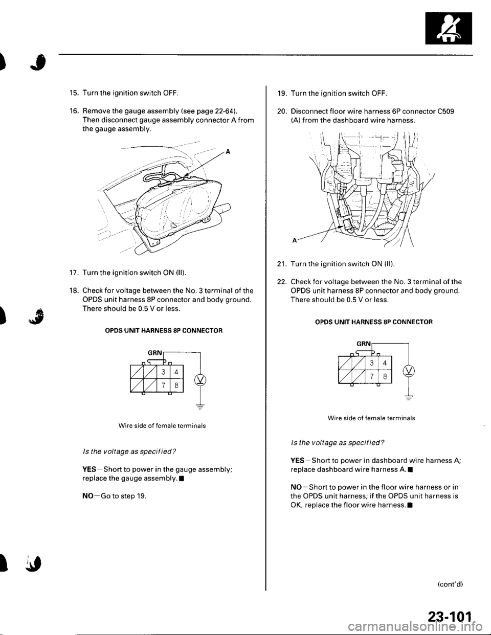
Remove the gauge assembly (see page 22-64).
Then disconnect gauge assembly connector A from
the gauge assembly.
Turn the ignition switch ON (ll).
Check for voltage between the No. 3 terminal of the
OPDS unit harness 8P connector and body ground.
There should be 0.5 V or less.
OPOS UNIT HARNESS 8P CONNECTOR
Wire side of female terminals
ls the voltage as specified?
YES Short to power in the gauge assembly;
replace the gauge assembly.l
NO Go to step 19.
)
A
\,I
19.
20.
22.
Turn the ignition switch OFF.
Disconnect floor wire harness 6P connector C509(A)from the dashboard wire harness.
Turn the ignition switch ON (ll).
Check for voltage between the No. 3 terminal of the
OPDS unit harness 8P connector and body ground.
There should be 0.5 V or less.
OPDS UNIT HARNESS 8P CONNECTOB
Wire side o{ female terminals
ls the voltage as specified?
YES Short to power in dashboard wire harness A;
replace dashboard wire harness A.l
NO-Short to power in the floor wire harness or in
the OPDS unit harness; if the OPDS unit harness is
OK, replace the floor wire harness.I
(cont'd)
23-101
Page 1109 of 1139

sRs
23.
24.
DTC Troubleshooting (cont'dl
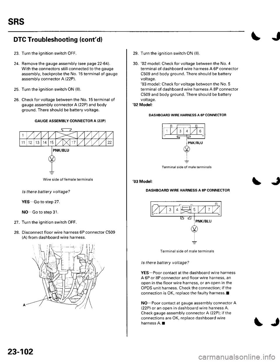
Turn the ignition switch OFF.
Remove the gauge assembly (see page 22-64l,.
With the connectors still connected to the gauge
assembly, backprobe the No. '15 terminal of gauge
assembly connector A (22P).
Turn the ignition switch ON {ll).
Check for voltage between the No. 15 terminal of
gauge assembly connector A {22P) and body
ground. There should be battery voltage.
GAUGE ASSEMBLY CONNECTOR A {22P)
Wire side of female terminals
ls thete battery voltage?
YES-Go to step 27.
NO Go to step 31.
Turn the ignition switch OFF.
Dlsconnect floor wire harness 6P connector C509
{A) from dashboard wire harness.
26.
27.
28.
23-102
\J
29. Turn the ignition switch ON (lli
30. '02 model: Checkforvoltage between the No.4
terminal of dashboard wire harness A 6P connector
C509 and body ground. There should be battery
vorlage.'03 model: Check for voltage between the No. 5
terminal of dashboard wire harness A 8P connector
C509 and body ground. There should be battery
vollage.'02 Model:
OASHBOARD WIRE HARNESS A 6P CONNECTOF
Terminal side of male terminals
'03 Model:
DASHBOARD WIRE HARNESS A 8P CONNECTOR
Terminal side of male terminals
ls there battety voltage?
YES Poor contact at the dashboard wire harness
A 6P or 8P connector and floor wire harness, an
open in the floor wire harness, or an open in the
OPDS unit harness. Check the connection; if the
connection is OK, replace the faulty harness.l
NO Poor contact at gauge assembly connector A
{22P) or an open in dashboard wire harness A.
Check gauge assembly connector A {22P); if the
connections are OK, replace dashboard wire
harness A.I
Page 1110 of 1139

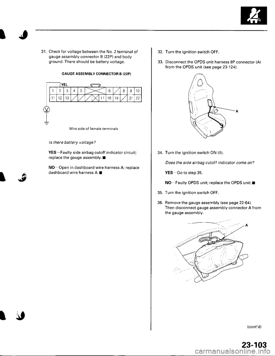
Check for voltage between the No. 2 terminal ofgauge assembly connector B (22P) and bodyground. There should be battery voltage.
GAUGE ASSEMBLY CONNECTOR B {22P)
Wire side of female terminals
ls there battery voltage?
YES Faulty side airbag cutoff indicator circuit;
replace the gauge assembly.l
NO Open in dashboard wire harness A; replace
dashboard wire harness A.I
YEL
12345X68910
1t12IJ,/1,/1,/)112122
\,
32.
33.
35.
36.
34.
Turn the ignition switch OFF.
Disconnect the OPDS unit harness 8P connector (A)
from the OPDS unit (see page 23- 124).
Turn the ignition switch ON (ll).
Does the slde airbag cutotf indicator come on?
YES Go to step 35.
NO Faulty OPDS unit; replace the OPDS unit.l
Turn the ignition switch OFF.
Remove the gauge assembly (see page 22-64).
Then disconnect gauge assembly connector A from
the gauge assembly.
(cont'd)
23-103