Page 384 of 429

This indicator should light when the
ignition switch is ON (II), and go out
af ter the engine starts. If it comes on
at any other time, it indicates one of
the engine’s emissions control
systems may have a problem. Even
though you may f eel no dif f erence in
your car’s perf ormance, it can
reduce your f uel economy and cause
your car to put out excessive
emissions. Continued operation may
cause serious damage.If you have recently ref ueled your
car, the cause of this indicator
coming on could be a loose or
missing f uel f ill cap. Check the cap
and tighten it until it clicks several
times. Replace the f uel f ill cap if it is
missing. Tightening the cap will not
make the indicator turn of f
immediately; it takes one driving trip.
If the indicator remains on past one
driving trip, or the f uel cap was not
loose or missing, have the car
checked by the dealer as soon as
possible. Drive moderately until the
dealer has inspected the problem.
Avoid full-throttle acceleration and
driving at high speed.
Youshouldalsohavethedealer
inspect your car if this indicator
comes on repeatedly, even though it
may turn of f as you continue driving.
This indicator may also come on
along with the ‘‘D’’ indicator.
Malf unction Indicator L amp
T aking Care of t he Unexpect ed381
MALFUNCTION INDICATOR LAMP
If you keep driving with the
malf unction indicator lamp on, you can
damage your car’s emissions controls
and engine. Those repairs may not be
covered by your car’s warranties.
Page 385 of 429
Your car has certain ‘‘readiness
codes’’ that are part of the on-board
diagnostics f or the emissions
systems. In some states, part of the
emissions testing is to make sure
these codes are set. If they are not
set, the test cannot be completed.
If your car’s battery has been
disconnected or gone dead, these
codes are erased. It takes several
days of driving under various
conditions to set the codes again.If possible, do not take your car f or a
state emissions test until the
readiness codes are set. Ref er to
State Emissions Testing f or more
inf ormation. (See page .)
To check if they are set, turn the
ignition ON (II), but do not start the
engine. The Malf unction Indicator
Lamp will come on f or 20 seconds. If
it then goes of f , the readiness codes
are set. If it blinks 5 times, the
readiness codes are not set.
408
Malf unction Indicator L amp
T aking Care of t he Unexpect ed
Readiness Codes
382
Page 386 of 429

�Î
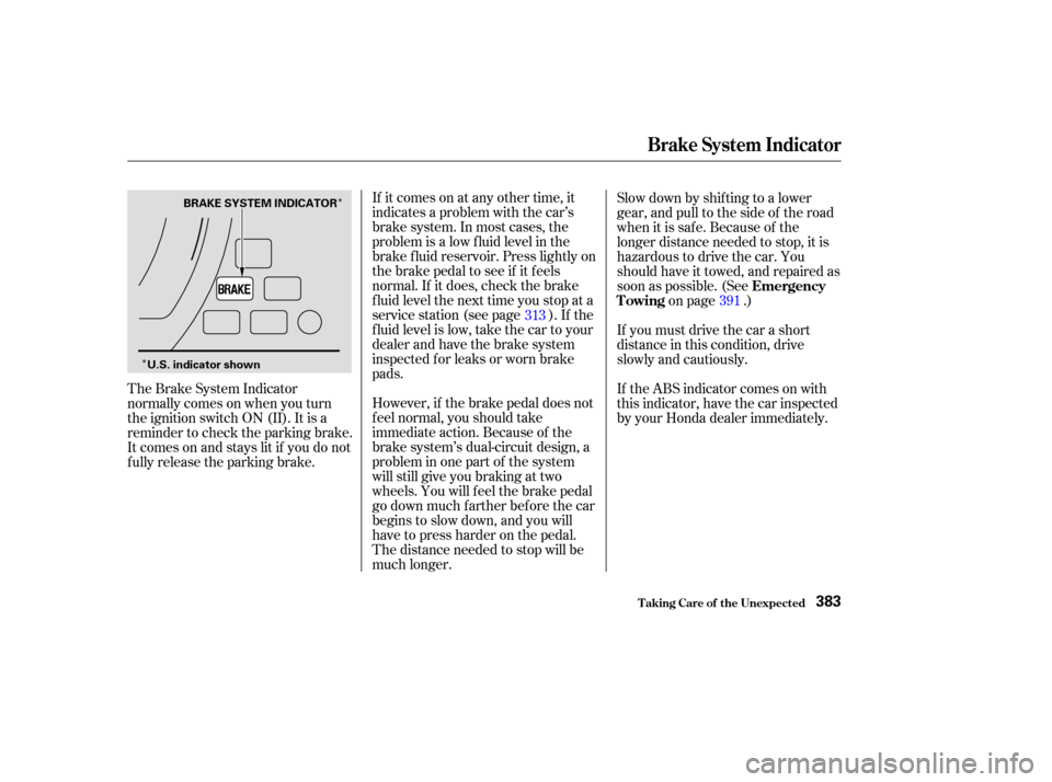
�ÎIf it comes on at any other time, it
indicates a problem with the car’s
brake system. In most cases, the
problem is a low f luid level in the
brake f luid reservoir. Press lightly on
the brake pedal to see if it f eels
normal. If it does, check the brake
f luid level the next time you stop at a
service station (see page ). If the
fluid level is low, take the car to your
dealer and have the brake system
inspected f or leaks or worn brake
pads.
However, if the brake pedal does not
f eel normal, you should take
immediate action. Because of the
brake system’s dual-circuit design, a
problem in one part of the system
will still give you braking at two
wheels. You will f eel the brake pedal
go down much f arther bef ore the car
begins to slow down, and you will
have to press harder on the pedal.
The distance needed to stop will be
much longer. Slow down by shif ting to a lower
gear, and pull to the side of the road
when it is saf e. Because of the
longer distance needed to stop, it is
hazardous to drive the car. You
should have it towed, and repaired as
soon as possible. (See
on page .)
The Brake System Indicator
normallycomesonwhenyouturn
the ignition switch ON (II). It is a
reminder to check the parking brake.
It comes on and stays lit if you do not
f ully release the parking brake. If you must drive the car a short
distance in this condition, drive
slowly and cautiously.
If the ABS indicator comes on with
this indicator, have the car inspected
by your Honda dealer immediately.
313
391Emergency
Towing
Brake System Indicator
T aking Care of t he Unexpect ed383
BRAKE SYSTEM INDICATOR
U.S. indicator shown
Page 389 of 429

All the electrical circuits in your car
have fuses to protect them from a
short circuit or overload. These
f uses are located in two f use boxes.The under-hood f use box is located
near the back of the engine compart-
ment on the driver’s side. To open it,
pushthetabsasshown. Remove the cover f rom the f use
box. Turn the ignition switch to LOCK
(0). Make sure the headlights and
all other accessories are off.
If something electrical in your car
stops working, the f irst thing you
should check f or is a blown f use.
Determine f rom the chart on pages
and , or the diagram on the
f use box lid, which f use or f uses
control that component. Check those
f uses f irst, but check all the f uses
bef ore deciding that a blown f use is
not the cause. Replace any blown
f uses and check the component’s
operation.
The interior f use box is on the
driver’s lower lef t side. To remove
the f use box lid, put your f inger in
the notch on the lid, and pull it
upward slightly, then pull it toward
you and take it out of its hinges. 1.
2.390
389
Fuses
T aking Care of t he Unexpect ed
Checking and Replacing Fuses
386
INTERIOR UNDER-HOOD
TAB
NOTCH
Page 393 of 429
�µ�µ
�µ
�Î
�µ
�µ
�µ
�µ
�ÎNo.
No. No. Amps.
Amps. Circuits Protected
Circuits Protected Amps. Circuits Protected
: On Canadian models
13
14
15
16
17
18
19
20
21
22
23
24
25
26
27
28
29
30
31
32
33
1
2
3
4
5
6 7
8
9
10
11
12 10 A
20 A
15 A
7.5 A 30 A
(15 A)
15 A
(10 A) 15 A
10 A
7.5 A Back-Up Lights
Door Lock
Front Accessory Sockets
IG OPDS
IG Wiper
Not Used
DBW
Ignition Coil
Daytime Running Light
Laf Heater
Radio
Interior Light (20 A)
(20 A)
(20 A)
15 A
15 A
7.5 A
7.5 A 10 A
7.5 A
20 A
20 A
(20 A)
7.5 A
7.5 A
7.5 A Not Used
Driver’s Power Seat Sliding
Heated Seats
Not Used
IG ACG
IG Fuel Pump
IG Washer
IG Meter
IG SRS
IGP (PGM-FI ECU)
Not Used
Not Used
Passenger’s Power Window
Driver’s Power Window
Moonroof
Not Used
IG HAC
Not Used
ACC
HAC OP
Driver’s Power Seat Reclining
Fuses
T aking Care of t he Unexpect ed390
INTERIOR FUSE BOX
Page 395 of 429
If you decide to tow your car with all
f our wheels on the ground, make
sure you use a properly-designed and
attached tow bar. Prepare the car for
towing as described above, and leave
the ignition switch in Accessory (I)
so the steering wheel does not lock.
Make sure the radio and any items
plugged into the accessory power
socket are turned of f so they do not
rundownthebattery.
Emergency T owing
T aking Care of t he Unexpect ed392
The steering system can be damaged if
the steering wheel is locked. Leave the
ignition switch in Accessory (I), and
make sure the steering wheel turns
f reely bef ore you begin towing.Trying to lif t or tow your car by the
bumpers will cause serious damage.
The bumpers are not designed to
support the car’s weight.
Page 396 of 429

Thediagramsinthissectiongive
you the dimensions and capacities of
your Honda, and the locations of the
identif ication numbers. It also
includes inf ormation you should
know about your car’s tires and
emissions control systems.................
Identif ication Numbers . 394
Specif ications ..................
(4-cylinder Models) . 396
Specif ications ..................
(6-cylinder Models) . 398
DOT Tire Quality Grading ............................
(U.S.Cars) .400
.................................
Treadwear .400
......................................
Traction .400
.............................
Temperature .401
...........................
Tire Inf ormation .402 .........................
Oxygenated Fuels .403
......
Driving in Foreign Countries . 404
.......................
Emissions Controls .405
.....................
The Clean Air Act .405
Crankcase Emissions Control ....................................
System .405
Evaporative Emissions Control ....................................
System .405
Onboard Ref ueling Vapor ................................
Recovery .405
...
Exhaust Emissions Controls . 406
....................
PGM-FI System .406
Ignition Timing Control ................................
System .406
Exhaust Gas Recirculation ...................
(EGR) System . 406
Three Way Catalytic ...........................
Converter .406
....................
Replacement Parts . 406
..
Three Way Catalytic Converter . 407
..............
State Emissions Testing . 408
T echnical Inf ormat ion
T echnical Inf ormation393
Page 409 of 429

The emissions control systems are
covered by warranties separate from
the rest of your car. Read your
warranty manual f or more informa-
tion. The emissions control systems are
designed and certif ied to work to-
gether in reducing emissions to
levels that comply with the Clean Air
Act. To make sure the emissions
remain low, you should use only new
genuine Honda replacement parts or
their equivalent f or repairs. Using
lowerqualitypartsmayincreasethe
emissions f rom your car.
The PGM-FI System uses sequential
multiport f uel injection.
It has three subsystems: Air Intake,
Engine Control, and Fuel Control.
The Engine Control Module (ECM)
or the Powertrain Control Module
(PCM) uses various sensors to
determine how much air is going
into the engine. It then controls how
much f uel to inject under all operat- ing conditions.
This system constantly adjusts the
ignition timing, reducing the amount
of HC, CO, and NOx produced.
The exhaust emissions controls
include f our systems: PGM-FI,
Ignition Timing Control, Exhaust
Gas Recirculation and Three Way
Catalytic Converter. These four
systems work together to control the
engine’s combustion and minimize
the amount of HC, CO, and NOx that
comes out the tailpipe. The exhaust
emissions control systems are
separate f rom the crankcase and
evaporative emissions control
systems. The Exhaust Gas Recirculation
(EGR) system takes some of the
exhaust gas and routes it back into
the intake manif old. Adding exhaust
gas to the air/f uel mixture reduces
the amount of NOx produced when
the f uel is burned.
The three way catalytic converter is
in the exhaust system. Through
chemical reactions, it converts HC,
CO, and NOx in the engine’s exhaust
to carbon dioxide (CO ), dinitrogen
(N ), and water vapor.
2
2
Replacement Parts
Exhaust Emissions Controls
PGM-FI Syst em Ignit ion T iming Cont rol Syst em
Exhaust Gas Recirculat ion (EGR)Syst em
Three Way Catalytic Converter
Emissions Cont rols
T echnical Inf ormation406