Page 2 of 200
Brakes 105
Traction control/AdvanceTrac 106
Transmission operation 108
Trailer towing 115
Roadside Emergencies 116
Getting roadside assistance 116
Hazard flasher switch 117
Fuel pump shut-off switch 118
Fuses and relays 118
Changing tires 127
Jump starting 132
Wrecker towing 138
Customer Assistance 139
Reporting safety defects (U.S. only) 147
Cleaning 148
Maintenance and Specifications 154
Engine compartment 155
Engine oil 156
Battery 159
Fuel information 167
Air filter(s) 178
Part numbers 182
Refill capacities 183
Lubricant specifications 184
Accessories 189
Index 191
All rights reserved. Reproduction by any means, electronic or mechanical
including photocopying, recording or by any information storage and retrieval
system or translation in whole or part is not permitted without written
authorization from Ford Motor Company. Ford may change the contents without
notice and without incurring obligation.
Copyright © 2002 Ford Motor Company
Table of Contents
2
Page 4 of 200

SAFETY AND ENVIRONMENT PROTECTION
Warning symbols in this guide
How can you reduce the risk of personal injury and prevent possible
damage to others, your vehicle and its equipment? In this guide, answers
to such questions are contained in comments highlighted by the warning
triangle symbol. These comments should be read and observed.
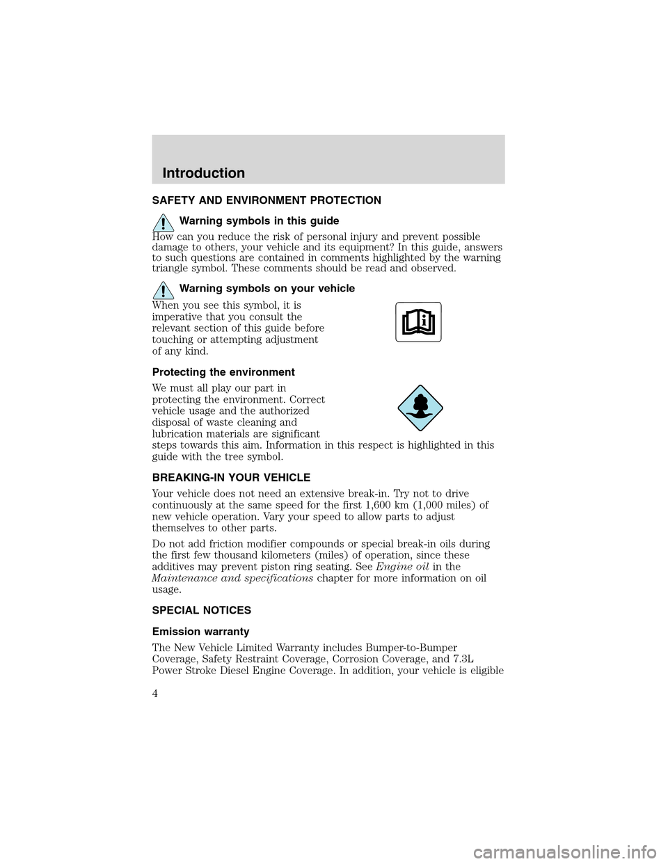
Warning symbols on your vehicle
When you see this symbol, it is
imperative that you consult the
relevant section of this guide before
touching or attempting adjustment
of any kind.
Protecting the environment
We must all play our part in
protecting the environment. Correct
vehicle usage and the authorized
disposal of waste cleaning and
lubrication materials are significant
steps towards this aim. Information in this respect is highlighted in this
guide with the tree symbol.
BREAKING-IN YOUR VEHICLE
Your vehicle does not need an extensive break-in. Try not to drive
continuously at the same speed for the first 1,600 km (1,000 miles) of
new vehicle operation. Vary your speed to allow parts to adjust
themselves to other parts.
Do not add friction modifier compounds or special break-in oils during
the first few thousand kilometers (miles) of operation, since these
additives may prevent piston ring seating. SeeEngine oilin the
Maintenance and specificationschapter for more information on oil
usage.
SPECIAL NOTICES
Emission warranty
The New Vehicle Limited Warranty includes Bumper-to-Bumper
Coverage, Safety Restraint Coverage, Corrosion Coverage, and 7.3L
Power Stroke Diesel Engine Coverage. In addition, your vehicle is eligible
Introduction
4
Page 18 of 200

RADIO RECEPTION FACTORS
There are three factors that can effect radio reception:
•Distance/strength: The further you travel from an FM station, the
weaker the signal and the weaker the reception.
•Terrain: Hills, mountains, tall buildings, power lines, electric fences,
traffic lights and thunderstorms can interfere with your reception.
•Station overload: When you pass a broadcast tower, a stronger signal
may overtake a weaker one and play while the weak station frequency
is displayed.
CD/CD PLAYER CARE
Do:
•Handle discs by their edges only. Never touch the playing surface.
•Inspect discs before playing. Clean only with an approved CD cleaner
and wipe from the center out.
Don’t:
•Expose discs to direct sunlight or heat sources for extended periods
of time.
•Insert more than one disc into each slot of the CD changer magazine.
•Clean using a circular motion.
CD units are designed to play commercially pressed 12 cm (4.75
in) audio compact discs only. Due to technical incompatibility,
certain recordable and re-recordable compact discs may not
function correctly when used in Ford CD players. Irregular
shaped CDs, CDs with a scratch protection film attached, and CDs
with homemade paper (adhesive) labels should not be inserted
into the CD player. The label may peel and cause the CD to
become jammed. It is recommended that homemade CDs be
identified with permanent felt tip marker rather than adhesive
labels. Ball point pens may damage CDs. Please contact your
dealer for further information.
AUDIO SYSTEM WARRANTY AND SERVICE
Refer to theWarranty Guidefor audio system warranty information. If
service is necessary, see your dealer or qualified technician.
Entertainment Systems
18
Page 22 of 200

•Do not place items over the
climate temperature sensor grid.
This may cause improper
operation of the system.
To aid in side window defogging/demisting in cold weather:
1. Select
2. Ensure that recirculation is disengaged.
3. Set the temperature control to full heat.
4. Set the highest fan speed
5. Direct the outer instrument panel vents towards the side windows.
To increase airflow to the outer instrument panel vents, close the vents
located in the middle of the instrument panel.
Do not place objects on top of the instrument panel as these
objects may become projectiles in a collision or sudden stop.
REAR WINDOW DEFROSTER
Press the rear window defroster
control to clear the rear window and
sideview mirrors of thin ice or fog.
The light above the control will
illuminate to indicate that the rear
defrost is operating.
The ignition must be in the RUN position and the engine running in
order to operate the rear window defroster.
The rear window defroster turns off automatically after a predetermined
amount of time, if a low battery condition is detected, or if the ignition is
turned to the OFF position. To manually turn off the rear window
defroster at any time, press the control again.
R
Climate Controls
22
Page 25 of 200
Daytime running lamps (DRL) (Canada Only)
Turns the lowbeam headlamps on with a reduced output.
To activate with automatic transmission:
•the ignition must be in the RUN position;
•the headlamp control is in the OFF position, Parking lamps position,
or Autolamp position when the autolamp function has not turned on
the headlamps (daytime); and
•the transmission is out of Park.
Always remember to turn on your headlamps at dusk or during
inclement weather. The Daytime Running Light (DRL) System
does not activate your tail lamps and generally may not provide
adequate lighting during these conditions. Failure to activate your
headlamps under these conditions may result in a collision.
High beams
Pull toward you until control stops
to activate. Repeat to deactivate.
Flash to pass
Pull toward you slightly to activate
and release to deactivate.
Lights
25
Page 33 of 200
Replacing tail/brake/turn/backup lamp bulbs
The tail/brake//turn/backup bulbs are located in the tail lamp assembly,
one just below the other. Follow the same steps to replace either bulb:
Prior to pulling the carpet away, in
step 1, the trunk trim scuff plate
must be removed. This can be
accomplished by pulling gently on
the component until the 6 push pins
along the rear of the trunk release.
The part can be placed aside and
the carpet pulled away. To replace
the piece, re-align the pins and push
into place.
1. Make sure the headlamp switch is
in the OFF position and then open
the trunk and carefully pull the
carpet away to expose the nut and
washer assemblies.
2. Remove the two nut and washer
assemblies from the lamp assembly.
3. Pull the lamp assembly towards
the rear of the vehicle disengaging
the ball stud locator from the ball
stud socket in the body. Carefully remove the lamp assembly from the
vehicle.
Lights
33
Page 35 of 200
MULTI-FUNCTION LEVER
Windshield wiper:Rotate the end
of the control away from you to
increase the speed of the wipers;
rotate towards you to decrease the
speed of the wipers.
Windshield washer:Push the end
of the stalk:
•briefly: causes a single swipe of
the wipers without washer fluid.
•a quick push and hold: the wipers
will swipe three times with
washer fluid.
•a long push and hold: the wipers and washer fluid will be activated for
up to ten seconds.
CHANGING THE WIPER BLADES
1. Pull the wiper arm away from the
vehicle. Turn the blade at an angle
from the wiper arm. Push the lock
pin manually to release the blade
and pull the wiper blade down
toward the windshield to remove it
from the arm.
2. Attach the new wiper to the
wiper arm and press it into place
until a click is heard.
3. Replace wiper blades every 6
months for optimum performance.
Driver Controls
35
Page 36 of 200

POWER TILT/TELESCOPE STEERING COLUMN
The steering column can be
adjusted manually by moving the
four-way rocker adjustment control
located below the turn signal/wiper
control stalk. Hold the control to
adjust.
The telescope function is adjusted
by moving the control toward the
driver to telescope out and toward
the instrument panel to telescope
in.
The tilt function is adjusted by moving the control up or down.
During easy exit, when you remove the key, the column will move to the
full in and up position. When the key is inserted into the ignition, the
column will return to the previous setting.
Never adjust the steering wheel when the vehicle is moving.
AUXILIARY POWER POINT
The power point is an additional
power source for electrical
accessories.
A power point is located on the
instrument panel.
Do not use the auxiliary power point
as a cigarette lighter.
The use of non-Ford approved electrical accessories could cause damage
not covered by your warranty.
Power outlets are designed for accessory plugs only. Do not hang
any type of accessory or accessory bracket from the plug.
Improper use of the power outlet can cause damage not covered
by your warranty.
P
A
S
S
E
N
G
E
R
A
I
R
B
A
G
OFF ON
Driver Controls
36