Page 1037 of 4378
22. Install the air cleaner outlet pipe. For additional information, refer to
Section 303 - 12 .
23. Connect the battery ground cable. For additional information, refer to Section 414 - 01 .
24. Fill the engine with clean engine oil.
25. CAUTION: Correct coolant bleeding is critical for correct engine cooling.
Fill and bleed the engine cooling system. For additional information, refer to Section 303 - 03A . �K�l�j . 12 �b�a
122003 Mustang Workshop Manual
17. 11. 2011file:///C:/Ford/2000 - 2004/tsocache/SHEF_4464/S3B~us~en~ ...
Page 1047 of 4378
IN-
VEHICLE REPAIR
Engine Support Insulators
Removal 1. Disconnect the battery ground cable (14301). For additional information, refer to Section 414 -
01 .
2. Remove the air cleaner outlet tube (9B659). For additional information, refer to Section 303 - 12 .
3. Remove the radiator sight shield (8C291).
4. Remove the coolant recovery reservoir (8A080). 1. Disconnect the hose.
2. Remove the bolts. 3. Remove the coolant recovery reservoir. SECTION 303-
01A: Engine — 3.8L 2003 Mustang Workshop Manual Special Tool(s)
3 Bar Engine Support Kit
303-
F072 Engine Lift Bracket Set
303-
D095 (D94L-6001- A) or
equivalent �K�l�j . 1 �b�a
82003 Mustang Workshop Manual
17. 11. 2011file:///C:/Ford/2000 - 2004/tsocache/SHEF_4464/S3B~us~en~ ...
Page 1053 of 4378
10. Lower the vehicle.
11. Remove the special tools.
12. Install the coolant recovery reservoir.
13. Install the radiator sight shield.
14. Install the air cleaner outlet tube. For additional information, refer to
Section 303 - 12 .
15. Connect the battery ground cable. For additional information, refer to Section 414 - 01 . �K�l�j . 7 �b�a
82003 Mustang Workshop Manual
17. 11. 2011file:///C:/Ford/2000 - 2004/tsocache/SHEF_4464/S3B~us~en~ ...
Page 1055 of 4378

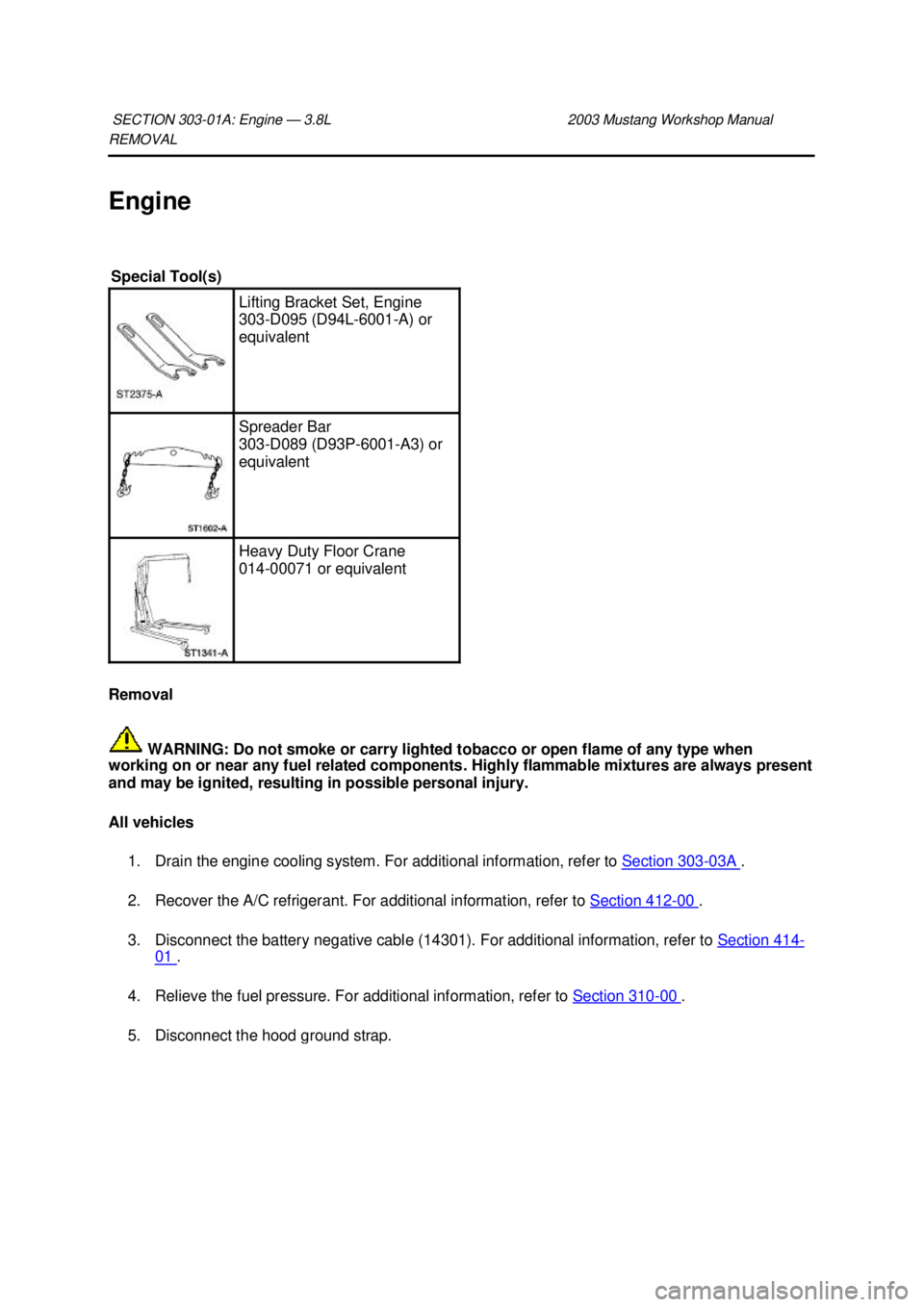
REMOVAL
Engine
Removal
WARNING: Do not smoke or carry lighted tobacco or open flame of any type when
working on or near any fuel related components. Highly flammable mixtures are always present
and may be ignited, resulting in possible personal injury.
All vehicles
1. Drain the engine cooling system. For additional information, refer to Section 303 - 03A .
2. Recover the A/C refrigerant. For additional information, refer to Section 412 - 00 .
3. Disconnect the battery negative cable (14301). For additional information, refer to Section 414 -
01 .
4. Relieve the fuel pressure. For additional information, refer to Section 310 - 00 .
5. Disconnect the hood ground strap. SECTION 303-
01A: Engine — 3.8L 2003 Mustang Workshop Manual Special Tool(s)
Lifting Bracket Set, Engine
303-
D095 (D94L-6001- A) or
equivalent Spreader Bar
303-
D089 (D93P-6001- A3) or
equivalent Heavy Duty Floor Crane
014-
00071 or equivalent �K�l�j . 1 �b�a
112003 Mustang Workshop Manual
17. 11. 2011file:///C:/Ford/2000 - 2004/tsocache/SHEF_4464/S3B~us~en~ ...
Page 1056 of 4378
6. Remove the hood (16612).
7. Disconnect the vacuum hose.
8. Disconnect the generator (10346).
1. Disconnect the connectors.
2. Remove the nut.
3. Remove the battery positive cable.
9. NOTE: Place a suitable container under the pump. �K�l�j . 2 �b�a
112003 Mustang Workshop Manual
17. 11. 2011file:///C:/Ford/2000 - 2004/tsocache/SHEF_4464/S3B~us~en~ ...
Page 1129 of 4378
40. Connect the battery negative cable. For additional information, refer to
Section 414 - 01 .
41. Fill the engine with clean engine oil.
42. Fill the engine cooling system. For additional information, refer to Section 303 - 03A .
43. Recharge the A/C refrigerant system. For additional information, refer to Section 412 - 00 .
44. Fill and bleed the power steering system. For additional information, refer to Section 211 - 00 . �K�l�j . 10 �b�a
102003 Mustang Workshop Manual
17. 11. 2011file:///C:/Ford/2000 - 2004/tsocache/SHEF_4464/S3B~us~en~ ...
Page 1133 of 4378

e
Specification in 90.200 mm diameter gauge.
f If applicable, measured vertically, +0.030- 0.050 mm (0.001-0.002 inch) measured horizontally (oval
pin bore).
g Pin bore and crank bearing bore must be parallel and in same vertical plane within the specified total
difference when measured at the ends of a 203 mm bar, 101.5 mm on each side of rod centerline.
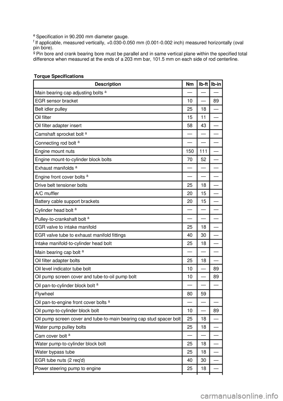
Torque Specifications Description Nm lb-
ft lb-
in Main bearing cap adjusting bolts
a — — —
EGR sensor bracket 10 — 89
Belt idler pulley 25 18 —
Oil filter 15 11 —
Oil filter adapter insert 58 43 —
Camshaft sprocket bolt
a — — —
Connecting rod bolt
a — — —
Engine mount nuts 150 111 —
Engine mount-
to-cylinder block bolts 70 52 —
Exhaust manifolds
a — — —
Engine front cover bolts
a — — —
Drive belt tensioner bolts 25 18 —
A/C muffler 20 15 —
Battery cable support brackets 20 15 —
Cylinder head bolt
a — — —
Pulley-
to-crankshaft bolt a — — —
EGR valve to intake manifold 25 18 —
EGR valve tube to exhaust manifold fittings 40 30 —
Intake manifold-
to-cylinder head bolt 25 18 —
Main bearing cap bolt
a — — —
Oil filter adapter bolts 25 18 —
Oil level indicator tube bolt 10 — 89
Oil pump screen cover and tube-
to-oil pump bolt 10 — 89
Oil pan-to-
cylinder block bolt a — — —
Flywheel 80 59
Oil pan-to-
engine front cover bolts a — — —
Oil pump-
to-cylinder block bolt 10 — 89
Oil pump screen cover and tube-
to-main bearing cap stud spacer bolt 25 18 —
Water pump pulley bolts 25 18 —
Cam cover bolt
a — — —
Water pump-
to-cylinder block bolt 25 18 —
Water bypass tube 25 18 —
EGR tube nuts (2 req'd) 40 30 —
Power steering pump to engine 25 18 — �K�l�j . 4 �b�a
62003 Mustang Workshop Manual
17. 11. 2011file:///C:/Ford/2000 - 2004/tsocache/SHEF_4464/S3B~us~en~ ...
Page 1134 of 4378

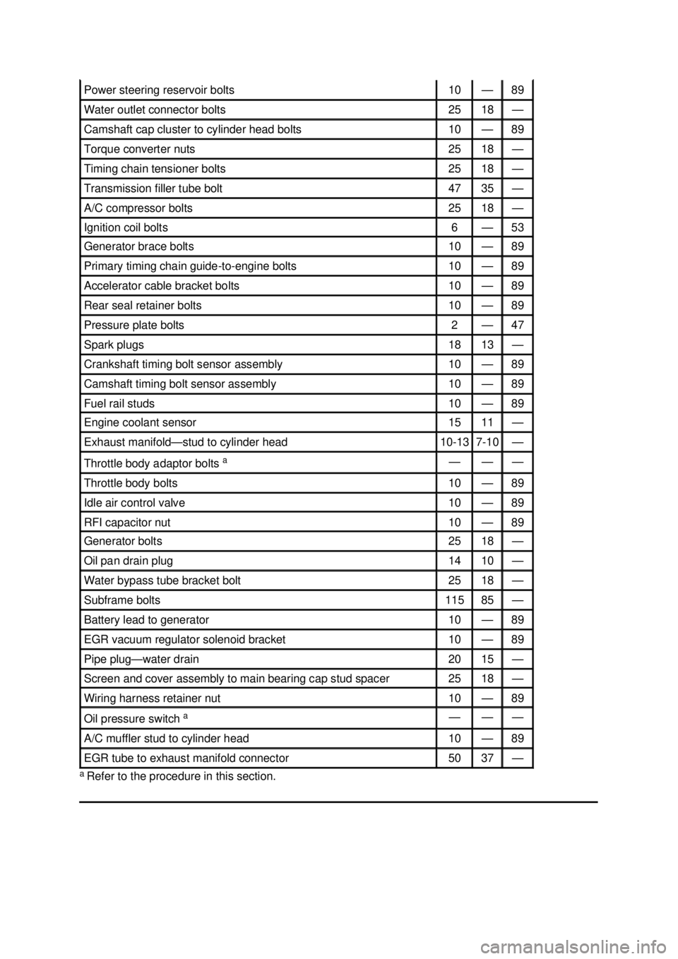
a
Refer to the procedure in this section. Power steering reservoir bolts 10 — 89
Water outlet connector bolts 25 18 —
Camshaft cap cluster to cylinder head bolts 10 — 89
Torque converter nuts 25 18 —
Timing chain tensioner bolts 25 18 —
Transmission filler tube bolt 47 35 —
A/C compressor bolts 25 18 —
Ignition coil bolts 6 — 53
Generator brace bolts 10 — 89
Primary timing chain guide-
to-engine bolts 10 — 89
Accelerator cable bracket bolts 10 — 89
Rear seal retainer bolts 10 — 89
Pressure plate bolts 2 — 47
Spark plugs 18 13 —
Crankshaft timing bolt sensor assembly 10 — 89
Camshaft timing bolt sensor assembly 10 — 89
Fuel rail studs 10 — 89
Engine coolant sensor 15 11 —
Exhaust manifold—
stud to cylinder head 10-
13 7-10 —
Throttle body adaptor bolts
a — — —
Throttle body bolts 10 — 89
Idle air control valve 10 — 89
RFI capacitor nut 10 — 89
Generator bolts 25 18 —
Oil pan drain plug 14 10 —
Water bypass tube bracket bolt 25 18 —
Subframe bolts 115 85 —
Battery lead to generator 10 — 89
EGR vacuum regulator solenoid bracket 10 — 89
Pipe plug—
water drain 20 15 —
Screen and cover assembly to main bearing cap stud spacer 25 18 —
Wiring harness retainer nut 10 — 89
Oil pressure switch
a — — —
A/C muffler stud to cylinder head 10 — 89
EGR tube to exhaust manifold connector 50 37 — �K�l�j . 5 �b�a
62003 Mustang Workshop Manual
17. 11. 2011file:///C:/Ford/2000 - 2004/tsocache/SHEF_4464/S3B~us~en~ ...