Page 3025 of 4378
REMOVAL AND INSTALLATION
Actuator Cable —
Speed Control
1. Remove the speed control actuator cable end from the throttle body. 1. Lift the speed control cable from the throttle nailhead.
2. Release the speed control cable from the throttle bracket.
2. Remove the speed control cable from the retaining clips.
3. Remove the LH front wheel and tire assembly. For additional information, refer to Section 204 -
04
4. Position aside the LH front splash shield.
1. Remove the pin- type retainers.
2. Remove the screws.
3. Position aside the LH front splash shield.
5. Depress the locking tab and rotate the speed control actuator cable cap to remove.
SECTION 310-
03: Speed Control 2003 Mustang Workshop Manual �K�l�j . 1 �b�a
22003 Mustang Workshop Manual
18. 11. 2011file:///C:/Ford/2000 - 2004/tsocache/SHEF_2308/S3B~us~en~ ...
Page 3027 of 4378
REMOVAL AND INSTALLATION
Actuator Cable —
Speed Control-Cobra
1. Remove the speed control actuator cable end from the throttle body. 1. Lift the speed control cable from the throttle nailhead.
2. Release the speed control cable from the throttle bracket.
2. Remove the speed control cable from the retaining clips.
3. Remove the LH front wheel and tire assembly. For additional information, refer to Section 204 -
04 .
4. Position aside the LH front splash shield. �zRemove the pin- type retainers.
�z Remove the screws.
5. Depress the locking tab and rotate the speed control actuator cable cap to remove.
SECTION 310-
03: Speed Control 2003 Mustang Workshop Manual �K�l�j . 1 �b�a
22003 Mustang Workshop Manual
18. 11. 2011file:///C:/Ford/2000 - 2004/tsocache/SHEF_2308/S3B~us~en~ ...
Page 3029 of 4378
REMOVAL AND INSTALLATION
Actuator —
Speed Control Servo
1. CAUTION: Electronic modules are sensitive to static electrical charges. If exposed
to these charges, damage may result.
Disconnect the battery ground cable.
2. Remove the LH wheel and tire; refer to Section 204 - 04 .
3. Position aside the LH front splash shield. 1. Remove the pin- type retainers.
2. Remove the screws.
3. Position aside the LH front splash shield.
4. Disconnect the speed control servo electrical connector.
5. Depress the locking tab and rotate the speed control actuator cable cap to remove.
SECTION 310-
03: Speed Control 2003 Mustang Workshop Manual �K�l�j . 1 �b�a
32003 Mustang Workshop Manual
18. 11. 2011file:///C:/Ford/2000 - 2004/tsocache/SHEF_2308/S3B~us~en~ ...
Page 3037 of 4378

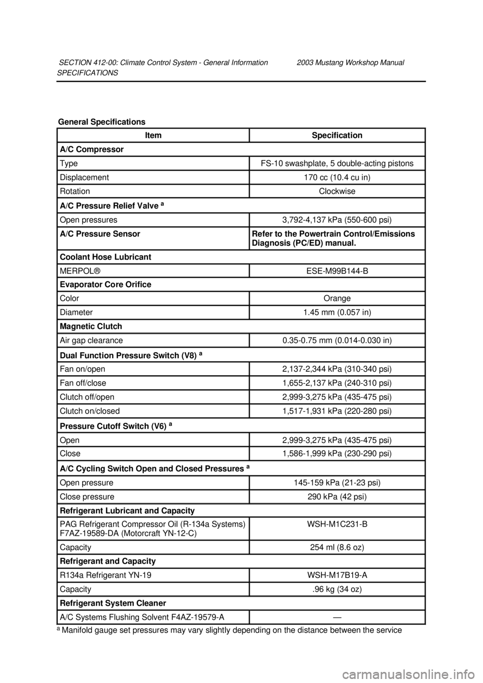
SPECIFICATIONS
a
Manifold gauge set pressures may vary slightly depending on the distance between the service
SECTION 412-
00: Climate Control System - General Information 2003 Mustang Workshop Manual General Specifications
Item Specification
A/C Compressor
Type FS-
10 swashplate, 5 double- acting pistons Displacement 170 cc (10.4 cu in)
Rotation Clockwise
A/C Pressure Relief Valve
a Open pressures 3,792-
4,137 kPa (550- 600 psi) A/C Pressure Sensor Refer to the Powertrain Control/Emissions
Diagnosis (PC/ED) manual.
Coolant Hose Lubricant
MERPOL® ESE-
M99B144- B Evaporator Core Orifice
Color Orange
Diameter 1.45 mm (0.057 in)
Magnetic Clutch
Air gap clearance 0.35-
0.75 mm (0.014- 0.030 in) Dual Function Pressure Switch (V8)
a Fan on/open 2,137-
2,344 kPa (310- 340 psi) Fan off/close 1,655-
2,137 kPa (240- 310 psi) Clutch off/open 2,999-
3,275 kPa (435- 475 psi) Clutch on/closed 1,517-
1,931 kPa (220- 280 psi) Pressure Cutoff Switch (V6)
a Open 2,999-
3,275 kPa (435- 475 psi) Close 1,586-
1,999 kPa (230- 290 psi) A/C Cycling Switch Open and Closed Pressures
a Open pressure 145-
159 kPa (21- 23 psi) Close pressure 290 kPa (42 psi)
Refrigerant Lubricant and Capacity
PAG Refrigerant Compressor Oil (R-134a Systems)
F7AZ- 19589- DA (Motorcraft YN-12- C) WSH-
M1C231- B Capacity 254 ml (8.6 oz)
Refrigerant and Capacity
R134a Refrigerant YN-
19 WSH-
M17B19- A Capacity .96 kg (34 oz)
Refrigerant System Cleaner
A/C Systems Flushing Solvent F4AZ-19579-
A — �K�l�j . 1 �b�a
22003 Mustang Workshop Manual
18. 11. 2011file:///C:/Ford/2000 - 2004/tsocache/SHEF_2308/S3B~us~en~ ...
Page 3077 of 4378

�z
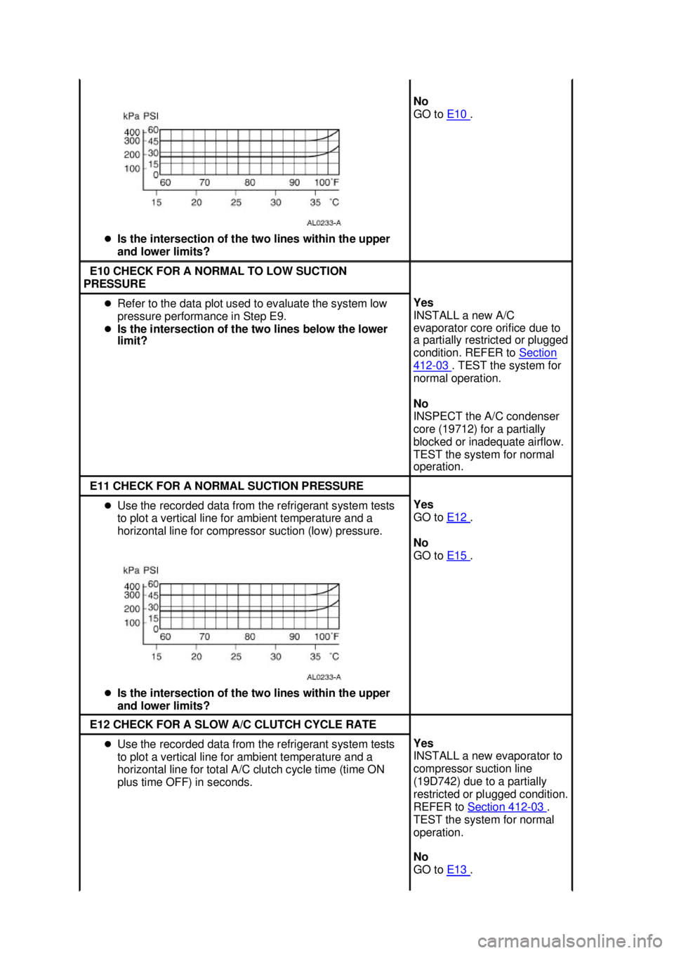
Is the intersection of the two lines within the upper
and lower limits? No
GO to
E10 .
E10 CHECK FOR A NORMAL TO LOW SUCTION
PRESSURE �z
Refer to the data plot used to evaluate the system low
pressure performance in Step E9.
�z Is the intersection of the two lines below the lower
limit? Yes
INSTALL a new A/C
evaporator core orifice due to
a partially restricted or plugged
condition. REFER to
Section 412 - 03 . TEST the system for
normal operation.
No
INSPECT the A/C condenser
core (19712) for a partially
blocked or inadequate airflow.
TEST the system for normal
operation. E11 CHECK FOR A NORMAL SUCTION PRESSURE
�z
Use the recorded data from the refrigerant system tests
to plot a vertical line for ambient temperature and a
horizontal line for compressor suction (low) pressure.
�z Is the intersection of the two lines within the upper
and lower limits? Yes
GO to
E12 .
No
GO to E15 .
E12 CHECK FOR A SLOW A/C CLUTCH CYCLE RATE
�z
Use the recorded data from the refrigerant system tests
to plot a vertical line for ambient temperature and a
horizontal line for total A/C clutch cycle time (time ON
plus time OFF) in seconds. Yes
INSTALL a new evaporator to
compressor suction line
(19D742) due to a partially
restricted or plugged condition.
REFER to
Section 412 - 03 .
TEST the system for normal
operation.
No
GO to E13 . �K�l�j . 28 �b�a
412003 Mustang Workshop Manual
18. 11. 2011file:///C:/Ford/2000 - 2004/tsocache/SHEF_2308/S3B~us~en~ ...
Page 3088 of 4378

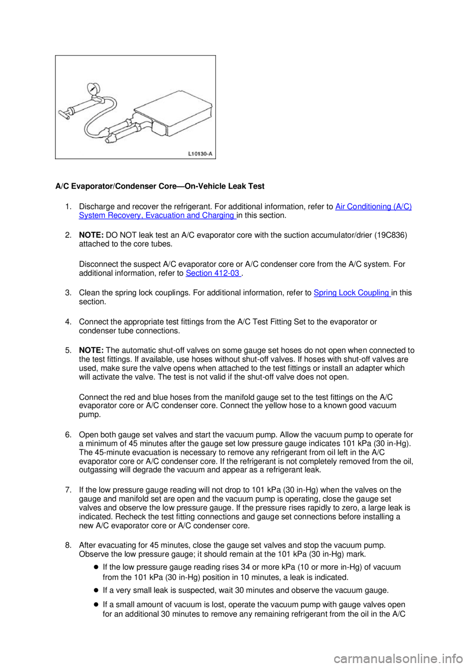
A/C Evaporator/Condenser Core—
On-Vehicle Leak Test
1. Discharge and recover the refrigerant. For additional information, refer to Air Conditioning (A/C) System Recovery, Evacuation and Charging in this section.
2. NOTE: DO NOT leak test an A/C evaporator core with the suction accumulator/drier (19C836)
attached to the core tubes.
Disconnect the suspect A/C evaporator core or A/C condenser core from the A/C system. For
additional information, refer to Section 412 - 03 .
3. Clean the spring lock couplings. For additional information, refer to Spring Lock Coupling in this
section.
4. Connect the appropriate test fittings from the A/C Test Fitting Set to the evaporator or condenser tube connections.
5. NOTE: The automatic shut- off valves on some gauge set hoses do not open when connected to
the test fittings. If available, use hoses without shut- off valves. If hoses with shut-off valves are
used, make sure the valve opens when attached to the test fittings or install an adapter which
will activate the valve. The test is not valid if the shut- off valve does not open.
Connect the red and blue hoses from the manifold gauge set to the test fittings on the A/C
evaporator core or A/C condenser core. Connect the yellow hose to a known good vacuum
pump.
6. Open both gauge set valves and start the vacuum pump. Allow the vacuum pump to operate for a minimum of 45 minutes after the gauge set low pressure gauge indicates 101 kPa (30 in- Hg).
The 45- minute evacuation is necessary to remove any refrigerant from oil left in the A/C
evaporator core or A/C condenser core. If the refrigerant is not completely removed from the oil,
outgassing will degrade the vacuum and appear as a refrigerant leak.
7. If the low pressure gauge reading will not drop to 101 kPa (30 in- Hg) when the valves on the
gauge and manifold set are open and the vacuum pump is operating, close the gauge set
valves and observe the low pressure gauge. If the pressure rises rapidly to zero, a large leak is
indicated. Recheck the test fitting connections and gauge set connections before installing a
new A/C evaporator core or A/C condenser core.
8. After evacuating for 45 minutes, close the gauge set valves and stop the vacuum pump. Observe the low pressure gauge; it should remain at the 101 kPa (30 in- Hg) mark.
�z If the low pressure gauge reading rises 34 or more kPa (10 or more in- Hg) of vacuum
from the 101 kPa (30 in- Hg) position in 10 minutes, a leak is indicated.
�z If a very small leak is suspected, wait 30 minutes and observe the vacuum gauge.
�z If a small amount of vacuum is lost, operate the vacuum pump with gauge valves open
for an additional 30 minutes to remove any remaining refrigerant from the oil in the A/C �K�l�j . 39 �b�a
412003 Mustang Workshop Manual
18. 11. 2011file:///C:/Ford/2000 - 2004/tsocache/SHEF_2308/S3B~us~en~ ...
Page 3093 of 4378
GENERAL PROCEDURES
Spring Lock Coupling
Disconnect
1. Remove the A/C tube lock coupling clip (19E746), if equipped.
2. Fit the special tool to the spring lock coupling.
3. Push the tool into the cage opening to release the female fitting from the A/C tube lock coupling spring (19E576).
SECTION 412-
00: Climate Control System - General Information 2003 Mustang Workshop Manual Special Tool(s)
Remover, Refrigerant Coupling
Set
412-
039 (T84L-19623- B) �K�l�j . 1 �b�a
62003 Mustang Workshop Manual
18. 11. 2011file:///C:/Ford/2000 - 2004/tsocache/SHEF_2308/S3B~us~en~ ...
Page 3094 of 4378
4. Pull the spring lock coupling fittings apart.
5.
CAUTION: Do not use metal tools to remove the O- ring seals. They can cause axial
scratches across the O- ring seal grooves, resulting in refrigerant leaks.
Remove the O- ring seals with a non- metallic tool.
6. CAUTION: Do not use a screwdriver or similar tool to remove the A/C tube lock
coupling spring; this can cause axial scratches across the O- ring seal grooves resulting
in refrigerant leaks.
Remove the A/C tube lock coupling spring with a small hooked wire. �K�l�j . 2 �b�a
62003 Mustang Workshop Manual
18. 11. 2011file:///C:/Ford/2000 - 2004/tsocache/SHEF_2308/S3B~us~en~ ...