Page 2969 of 4378
GENERAL PROCEDURES
Fittings
—R-Clip
Disconnect WARNING: Do not smoke or carry lighted tobacco or open flame of any type when
working on or near any fuel- related components. Highly flammable mixtures are always present
and may be ignited, resulting in possible personal injury.
WARNING: Fuel in the fuel system remains under high pressure even when the engine is
not running. Before servicing or disconnecting any of the fuel lines or fuel system components,
the fuel system pressure must be relieved to prevent accidental spraying of fuel, causing
possible personal injury or a fire hazard.
CAUTION: Do not use any tools. The use of tools may cause a deformity in the clip
components which may cause fuel leaks.
1. Relieve the fuel system pressure. For additional information, refer to Pressure Relief in this
section.
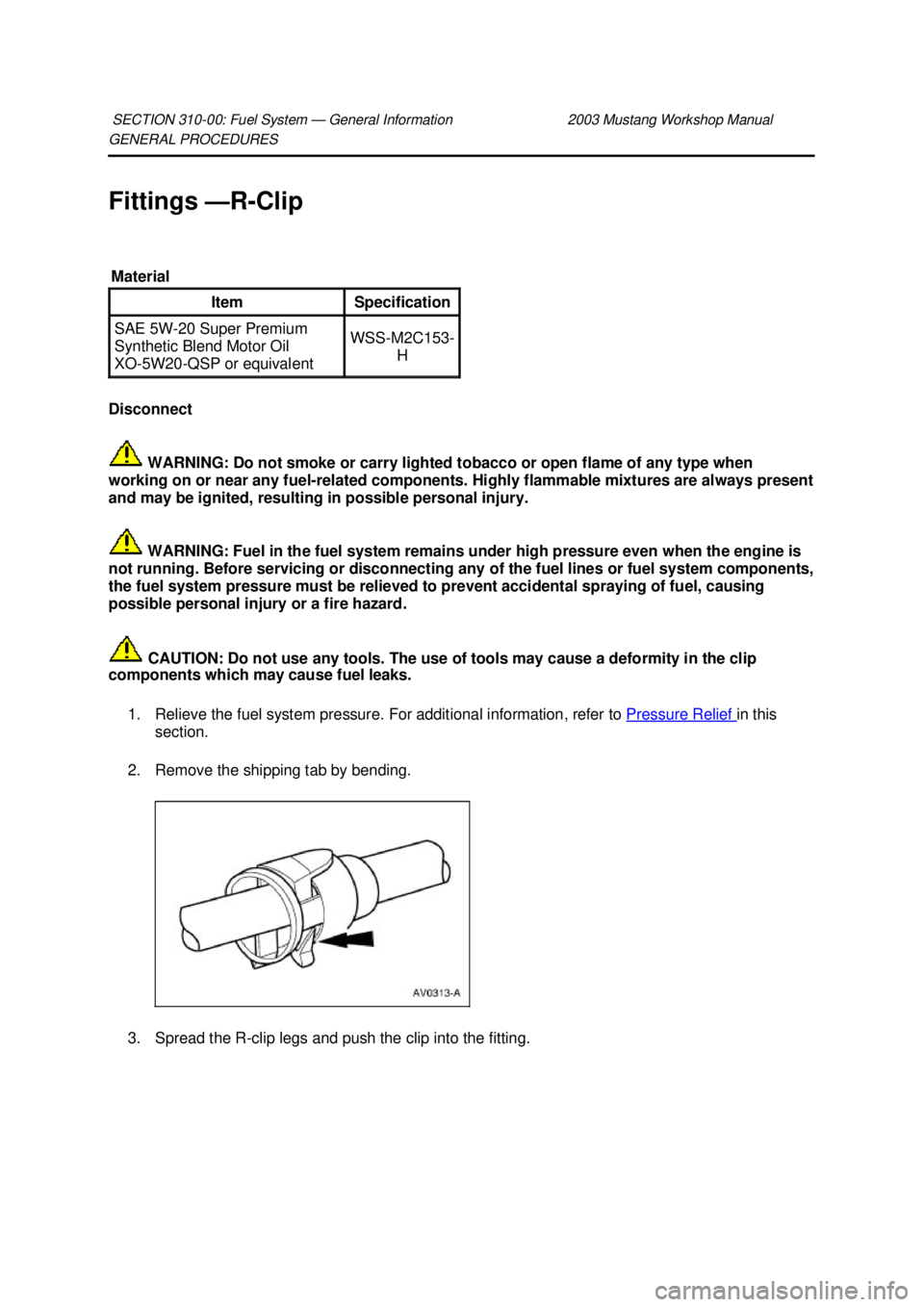
2. Remove the shipping tab by bending.
3. Spread the R- clip legs and push the clip into the fitting.
SECTION 310-
00: Fuel System — General Information 2003 Mustang Workshop Manual Material
Item Specification
SAE 5W-
20 Super Premium
Synthetic Blend Motor Oil
XO- 5W20- QSP or equivalent WSS-
M2C153-
H �K�l�j . 1 �b�a
32003 Mustang Workshop Manual
18. 11. 2011file:///C:/Ford/2000 - 2004/tsocache/SHEF_2308/S3B~us~en~ ...
Page 2975 of 4378
DESCRIPTION AND OPERATION
Fuel Tank And Lines
WARNING: Do not smoke, carry lighted tobacco or an open flame of any type when
working on or near any fuel- related component. Highly flammable mixtures are always present
and may be ignited, possibly resulting in personal injury.
The vehicle utilizes a returnless fuel system consisting of:
�zthe fuel tank.
�z a fuel tank filler pipe which contains a restrictor plate to permit only unleaded fuel to be pumped
into the fuel tank.
�z a 1/8 turn fuel tank filler cap.
�z a fuel filter providing filtration to protect the fuel injectors.
�z a single fuel line accommodating the returnless fuel system.
�z a fuel injection supply manifold which contains a differential pressure sensor and a fuel
temperature sensor.
�z a fuel pump and sender assembly which provides pressurized fuel to the engine and contains:
�„an inlet filter.
�„ a check valve which maintains system pressure after the pump is shut off.
�„ a pressure relief valve for overpressure protection in the event of restricted flow.
The fuel pump is controlled by an electronic fuel pump driver module which is enabled by the
powertrain control module (PCM). Electrical power to the fuel pump is provided through the inertia fuel
shutoff (IFS) switch, which is located in the luggage compartment. SECTION 310-
01: Fuel Tank and Lines 2003 Mustang Workshop Manual �K�l�j . 1 �b�a
12003 Mustang Workshop Manual
18. 11. 2011file:///C:/Ford/2000 - 2004/tsocache/SHEF_2308/S3B~us~en~ ...
Page 2977 of 4378
REMOVAL AND INSTALLATION
Fuel Tank
Removal
WARNING: Do not smoke, carry lighted tobacco or an open flame of any type when
working on or near any fuel- related components. Highly flammable mixtures are always present
and may be ignited, possibly resulting in personal injury.
WARNING: Fuel supply lines on all vehicles equipped with fuel injected engines will
remain pressurized for long periods of time after engine shutdown. Fuel system pressure must
be relieved prior to fuel system service to prevent possible personal injury or a fire hazard.
1. Disconnect the battery. For additional information, refer to Section 414 - 01 .
2. Relieve the fuel system pressure. For additional information, refer to Section 310 - 00 .
3. Drain the fuel tank. For additional information, refer to Section 310 - 00 .
4. Raise the vehicle. For additional information, refer to Section 100 - 02 .
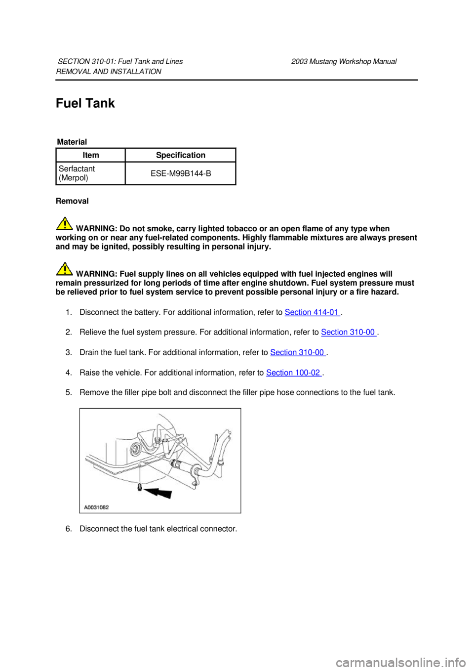
5. Remove the filler pipe bolt and disconnect the filler pipe hose connections to the fuel tank.
6. Disconnect the fuel tank electrical connector.
SECTION 310-
01: Fuel Tank and Lines 2003 Mustang Workshop Manual Material
Item Specification
Serfactant
(Merpol)
ESE-
M99B144- B �K�l�j . 1 �b�a
52003 Mustang Workshop Manual
18. 11. 2011file:///C:/Ford/2000 - 2004/tsocache/SHEF_2308/S3B~us~en~ ...
Page 2982 of 4378
REMOVAL AND INSTALLATION
Support Straps
Removal
WARNING: Do not smoke, carry lighted tobacco or an open flame of any type when
working on or near any fuel- related components. Highly flammable mixtures are always present
and may be ignited, possibly resulting in personal injury.
WARNING: Fuel supply lines on all vehicles equipped with fuel injected engines will
remain pressurized for long periods of time after engine shutdown. Fuel system pressure must
be relieved prior to fuel system service to prevent possible personal injury or a fire hazard.
1. Remove the fuel tank. For additional information, refer to Fuel Tank in this section.
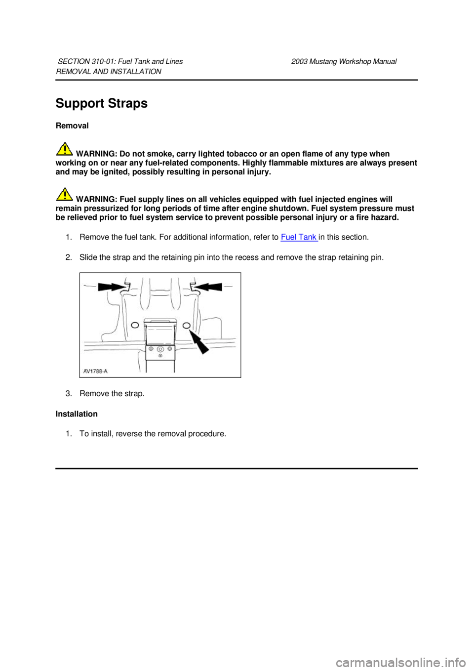
2. Slide the strap and the retaining pin into the recess and remove the strap retaining pin.
3. Remove the strap.
Installation 1. To install, reverse the removal procedure.
SECTION 310-
01: Fuel Tank and Lines 2003 Mustang Workshop Manual �K�l�j . 1 �b�a
22003 Mustang Workshop Manual
18. 11. 2011file:///C:/Ford/2000 - 2004/tsocache/SHEF_2308/S3B~us~en~ ...
Page 3475 of 4378
GENERAL PROCEDURES
Headlamp Adjustment
Headlamp Aiming
1. The headlamp aiming procedure depends on the type of beam pattern the headlamp is equipped with. Vehicles may come equipped with visual optical right (VOR), visual optical left
(VOL), or SAE only (includes sealed beam type) headlamps. To identify the headlamp beam
pattern, look on the headlamp lens. Molded in small letters on the headlamp lens is one of the
following:
�zSAE
�z VOR or SAE
�z VOL or SAE
2. Once the headlamp beam pattern is identified, aim the headlamps using one of the following methods as applicable.
�zPhotometric aimers can aim SAE, VOR and VOL type headlamps. This is the preferred
method of headlamp aiming.
�z Visual or screen method aiming can be used to aim SAE, VOR and VOL type
headlamps.
�z Mechanical aimers can be used only with SAE type headlamps. Lamps that can be
aimed mechanically will have three nibs molded into the lens of the lamp.
Photometric Aiming 1. For the photometric aiming procedure, refer to the appropriate photometric headlamp aimer instruction manual.
Screen Method Aiming
All headlamp types
NOTE: Horizontal aim is not necessary for VOR or VOL headlamps.
NOTE: Consult your state vehicle inspection manual for recommended tolerance ranges for visual
aiming.
NOTE: The sight shield may need to be positioned or removed for access to the adjusters.
1. Before starting headlamp adjustment: �zCheck the tire inflation.
�z Check that no other load is in the vehicle other than a half tank of fuel.
�z Check that the headlamps are clean.
�z Check for correct headlamp operation.
SECTION 417-
01: Exterior Lighting 2003 Mustang Workshop Manual �K�l�j . 1 �b�a
42003 Mustang Workshop Manual
18. 11. 2011file:///C:/Ford/2000 - 2004/tsocache/SHEF_5108/S3B~us~en~ ...
Page 3972 of 4378
REMOVAL AND INSTALLATION
Rear Bumper Cover
Removal and Installation
1. Remove the luggage compartment trim panel covers.
2. Remove the seven rear bumper cover nuts.
3. Remove the fuel drain hose.
4. Remove the four bumper cover screws (two each side).
5. Remove the pin- type retainers and the rear bumper cover.
SECTION 501-
19: Bumpers 2003 Mustang Workshop Manual �K�l�j . 1 �b�a
22003 Mustang Workshop Manual
18. 11. 2011file:///C:/Ford/2000 - 2004/tsocache/SHEF_5108/S3B~us~en~ ...